EP0218101A1 - Injection-moulding machine with a product withdrawal device - Google Patents
Injection-moulding machine with a product withdrawal device Download PDFInfo
- Publication number
- EP0218101A1 EP0218101A1 EP86112270A EP86112270A EP0218101A1 EP 0218101 A1 EP0218101 A1 EP 0218101A1 EP 86112270 A EP86112270 A EP 86112270A EP 86112270 A EP86112270 A EP 86112270A EP 0218101 A1 EP0218101 A1 EP 0218101A1
- Authority
- EP
- European Patent Office
- Prior art keywords
- injection molding
- molding machine
- injection
- guide
- slide
- Prior art date
- Legal status (The legal status is an assumption and is not a legal conclusion. Google has not performed a legal analysis and makes no representation as to the accuracy of the status listed.)
- Granted
Links
Images


Classifications
-
- B—PERFORMING OPERATIONS; TRANSPORTING
- B29—WORKING OF PLASTICS; WORKING OF SUBSTANCES IN A PLASTIC STATE IN GENERAL
- B29C—SHAPING OR JOINING OF PLASTICS; SHAPING OF MATERIAL IN A PLASTIC STATE, NOT OTHERWISE PROVIDED FOR; AFTER-TREATMENT OF THE SHAPED PRODUCTS, e.g. REPAIRING
- B29C45/00—Injection moulding, i.e. forcing the required volume of moulding material through a nozzle into a closed mould; Apparatus therefor
- B29C45/17—Component parts, details or accessories; Auxiliary operations
- B29C45/40—Removing or ejecting moulded articles
- B29C45/42—Removing or ejecting moulded articles using means movable from outside the mould between mould parts, e.g. robots
Definitions
- the invention relates to an injection molding machine with a device for linear injection molding removal from the open injection mold, in which a cross support or slide with a hanging link carried by it, which sits at its lower end, is movable on a guide bed aligned above the clamping unit for the injection mold Injection-molded gripper adjustable in the upward direction, which in turn is adjustable relative to the hanging link by at least two joints, each directed at right angles to one another, the guide bed for the cross support or slide being aligned parallel to the actuating direction of the clamping unit or to the longitudinal axis of the injection molding machine.
- injection molding removal devices work here with a cross support that can be moved along the guide bed, which requires a high level of technical complexity and also a considerable construction due to weight.
- the carriage carrying the hanging link of the cross support seated on the guide bed is designed as a cantilever arm or extension arm which can be moved in the up and down direction and which extends with a relatively large length above the clamping unit parallel to its actuating direction and forms the guide for a third carriage which does this actual link characterizes.
- the invention has for its object to provide an injection molding removal device of the initially specified type for injection molding machines, which can be realized not only with a structurally reduced effort, but also with a reduced construction weight. At the same time, however, an assignment of the injection molding removal device to the injection molding machine is also sought, which manages with a minimal installation space on the side next to the injection molding machine and thus enables a relatively close juxtaposition of adjacent injection molding machines.
- cross support or slide holds or forms a support or boom, at the free end of which the hanging link can only be displaced in height on a vertical plane passing through the longitudinal axis of the clamping unit is arranged that the guide bed is attached directly to or on the frame or housing of the injection molding machine and that the guide bed protrudes at least with its one end over the end face of the injection molding machine or over its closing unit for the injection mold.
- a structurally simple injection molding removal device working as a linear removal device which has a low construction weight and thereby ensures in a simple manner that the storage of the injection molded parts removed from the injection mold in front of and / or behind the rear of the Injection molding machine can take place where a favorable arrangement of stacking and / or conveying devices is possible.
- a relatively close juxtaposition of adjacent injection molding machines is possible.
- this injection molding removal device essentially only works with linear movements, it can be operated precisely and without any problems using program control. Thanks to the free programmability of the motion sequences, the shortest travel paths can be achieved.
- the injection molding removal device can also be designed in such a way that the suspension link consists of a linear guide coupling gear designed as a cardan or elliptical link or as a pantograph, the sliding guide of which on the slide or on the carrier or boom held by it is oriented across its own direction of movement.
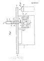
- the injection molding machine 1 shown in the drawing is equipped at one end with a clamping unit 2 for the injection molding tool 3, which has two mold halves 3a and 3b. While the mold half 3a sits on a tool carrier plate 4a of the clamping unit 2, which can be adjusted horizontally along guide rods 4c, the mold half 3b is fastened on a tool carrier plate 4b, which is fixed in position on the guide rods 4c.
- the injection mold 3 can optionally be opened and closed within the clamping unit 2 in the direction of the longitudinal axis 5-5. 1 and 3 of the drawing, the injection mold 3 is shown in the open state, that is to say with the mold halves 3a and 3b moved apart.
- An injection molding removal device 7, which is assigned to the injection molding machine 1, is used to remove the injection molded parts 6 from the injection mold 3.
- the injection molding removal device 7 has a stationary guide bed 8 which extends parallel to the actuating direction of the clamping unit 2, that is to say parallel to its longitudinal axis 5-5, and is also aligned with the longitudinal direction of the injection molding machine 1.
- the guide bed 8 is rigidly connected to the frame or housing of the injection molding machine 1 via a plurality of support arms 9.
- the guide bed 8 carries a longitudinally movable main carriage 10, the one has vertically upward spar 11, on which there is a guide track 12, on which in turn a carriage 13 is slidably arranged.
- the main slide 10 and the slide 13 guided on its spar 11 form a kind of cross support with one another, which has two axes of movement directed at right angles to one another, namely the horizontal Z axis and the vertical Y axis.
- the carriage 13 forms a carrier or cantilever, at the free end of which there is arranged a hanging member 14 which carries at its lower end an injection-molded gripper which, on the one hand, is rotatable about its longitudinal axis and, on the other hand, is pivotable with the hanging member 14 about a transverse axis.
- the arrangement of the injection molding gripper 15 on the hanging member 14 is such that its longitudinal axis coincides with a vertical plane which passes through the longitudinal axis 5-5 of the clamping unit 2, as can be clearly seen in FIG. 2.
- the hanging member 14 and the molded gripper 15 suspended thereon can be lowered in the vertical direction between the guide rods 4c into the clamping unit 2 when it is open, i.e. its tool carrier plates 4a and 4b with the two mold halves 3a and 3b of the injection mold 3 are moved apart, as shown in FIGS. 1 and 3.
- the gripper 15 the individual molded parts can then be removed from the open injection mold 3 in a program-controlled manner and transported away from the working area of the injection molding machine 1.
- the guide bed 8 of the injection molding removal device 7 is extended at least beyond the end face of the injection molding machine 1 or beyond its closing unit 2. However, the guide bed 8 can preferably also be guided beyond the rear of the injection molding machine 1.
- the hanging link 14 is arranged on the slide 13 of the cross support, which is effective as a carrier or cantilever, in its effective length so that it can be optimally adapted to different working conditions, without the movement range of the slide 13 in the direction of this Y axis is affected.
- the arrangement of the injection molding removal device 7 described above relative to the injection molding machine 1 is not only usable where the ' link member 14 is held and guided by a cross support. Rather, it can also be used when the suspension link consists of a linear guide coupling gear 17 designed as a cardan or elliptical link or also as a pantograph, the sliding guide 18 of which is located on a slide 19 which is movable along the guide bed 8.
- the sliding guide 18 for the straight guide coupling gear extends parallel to the guide bed 8 on the slide 19, but essentially transversely to the direction of movement of the free end of the hanging link -14, on which the injection molding gripper 15 is located.
Landscapes
- Engineering & Computer Science (AREA)
- Robotics (AREA)
- Manufacturing & Machinery (AREA)
- Mechanical Engineering (AREA)
- Moulds For Moulding Plastics Or The Like (AREA)
- Injection Moulding Of Plastics Or The Like (AREA)
- Manufacturing Optical Record Carriers (AREA)
Abstract
Description
Die Erfindung betrifft eine Spritzgießmaschine mit einer Vorrichtung zum linearen Spritzling-Entnahme aus dem geöffenten Spritzwerkzeug, bei welcher an einem oberhalb der Schließeinheit für das Spritzwerkzeug ausgerichteten Führungsbett ein Kreuzsupport bzw. Schlitten mit einem von ihm getragenen Hängeglied verfahrbar sitzt, das an seinem unteren Ende einen in Aufwärtsrichtung verstellbaren Spritzling-Greifer trägt, welcher wiederum um mindestens zwei jeweils rechtwinklig zueinander gerichtete Gelenke relativ zum Hängeglied verstellbar ist, wobei das Führungsbett für den Kreuzsupport oder Schlitten parallel zu Betätigungsrichtung der Schließeinheit bzw. zur Längsachse der Spritzgießmaschine ausgerichtet ist.The invention relates to an injection molding machine with a device for linear injection molding removal from the open injection mold, in which a cross support or slide with a hanging link carried by it, which sits at its lower end, is movable on a guide bed aligned above the clamping unit for the injection mold Injection-molded gripper adjustable in the upward direction, which in turn is adjustable relative to the hanging link by at least two joints, each directed at right angles to one another, the guide bed for the cross support or slide being aligned parallel to the actuating direction of the clamping unit or to the longitudinal axis of the injection molding machine.
Eine Spritzling-Entnahmevorrichtung dieser Art ist in der Zeitschrift "Plastverarbeiter" 1985, Nr. 6, Seiten 106 bis 109 beschrieben.An injection molding device of this type is described in the magazine "Plastverarbeiter" 1985, No. 6, pages 106 to 109.
Diese Spritzling-Entnahmevorrichtungen arbeiten dabei mit einem entlang dem Führungsbett verfahrbaren Kreuzsupport, der einen hohen technischen Aufwand erfordert und außerdem ein beträchtliches Konstrukti-onsgewicht bedingt. Der das Hängeglied tragende Schlitten des auf dem Führungsbett sitzenden Kreuzsupports ist als in Auf- und Abwärtsrichtung verfahrbarer Kragarm bzw. Ausleger ausgeführt, welcher sich mit relativ großer Länge oberhalb der Schließeinheit parallel zu deren Betätigungsrichtung erstreckt und die Führung für einen dritten Schlitten bildet, der das eigentliche Hängeglied prägt.These injection molding removal devices work here with a cross support that can be moved along the guide bed, which requires a high level of technical complexity and also a considerable construction due to weight. The carriage carrying the hanging link of the cross support seated on the guide bed is designed as a cantilever arm or extension arm which can be moved in the up and down direction and which extends with a relatively large length above the clamping unit parallel to its actuating direction and forms the guide for a third carriage which does this actual link characterizes.
Es ist offensichtlich, daß sich bei der Ausstattung von Spritzgießmaschinen mit diesen bekannten Spritzling-Entnahmevorrichtungen häufigschwierigkeiten ergeben, weil nicht nur das hohe Konstruktionsgewicht derselben in die Spritzgießmaschine eingeleitet werden muß, sondern weil auch seitlich neben der Spritzgießmaschine eine relativ großer Freiraum benötigt wird, um die mittels des Greifers erfaßten und aus dem Spritzwerkzeug heraustransportierten Spritzlinge ablegen zu können.It is obvious that there are often difficulties in equipping injection molding machines with these known injection molding removal devices because not only the high structural weight of the same has to be introduced into the injection molding machine, but also because a relatively large free space is required to the side of the injection molding machine to allow for the to be able to deposit molded parts which have been gripped by the gripper and transported out of the injection mold.
Der Erfindung liegt die Aufgabe zugrunde, für Spritzgießmaschinen eine Spritzling-Entnahmevorrichtung der anfangs spezifizierten Gattung zu schaffen, die sich nicht nur mit baulich vermindertem Aufwand, sondern auch mit einem verringerten Konstruktionsgewicht realisieren läßt. Zugleich wird aber auch eine Zuordnung der Spritzling-Entnahmevorrichtung zur Spritzgießmaschine angestrebt, die mit minimalem Einbauraum seitlich neben der Spritzgießmaschine auskommt und somit eine realtiv enge Nebeneinander-Anordnung einander benachbarter Spritzgießmaschinen ermöglicht.The invention has for its object to provide an injection molding removal device of the initially specified type for injection molding machines, which can be realized not only with a structurally reduced effort, but also with a reduced construction weight. At the same time, however, an assignment of the injection molding removal device to the injection molding machine is also sought, which manages with a minimal installation space on the side next to the injection molding machine and thus enables a relatively close juxtaposition of adjacent injection molding machines.
Die Lösung dieser Aufgabe basiert nach der Erfindung auf dem Kennzeichnungsmerkmal des Anspruchs 1 und wird dadurch erreicht, daß der Kreuzsupport bzw.Schlitten einen Träger oder Ausleger hält oder bildet, an dessen freiem Ende das Hängeglied ausschließlich auf einer durch die Längsachse der Schließeinheit gehenden Vertikalebene höhenverlagerbar angeordnet ist, daß das Führungsbett über Tragarme unmittelbar an bzw. auf dem Gestell oder Gehäuse der Spritzgießmaschine befestigt ist und daß dabei das Führungsbett zumindest mit seinem einen Ende bis über die Stirnseite der Spritzgießmaschine bzw. über deren Schließeinheit für das Spritzwerkzeug hinausragt.This object is achieved according to the invention on the characterizing feature of
Durch diese erfindungsgemäßen Lösungsmerkmale wird eine als Linear-Entnahmegerät arbeitende, baulich einfache Spritzling-Entnahmevorrichtung geschaffen, die ein geringes Konstruktionsgewicht hat und dabei auf einfache Weise sicherstellt, daß die Ablage der aus dem Spritzwerkzeug entnommenen Spritzlinge vor der Stirnseite und/oder hinter der Rückseite der Spritzgießmaschine erfolgen kann, wo eine günstige Anordnung von Stapel- und/oder Fördervorrichtungen möglich ist. Eine relativ enge Nebeneinander-Anordnung einander benachbarter Spritzgießmaschinen ist hierdurch möglich.By means of these solution features according to the invention, a structurally simple injection molding removal device working as a linear removal device is created, which has a low construction weight and thereby ensures in a simple manner that the storage of the injection molded parts removed from the injection mold in front of and / or behind the rear of the Injection molding machine can take place where a favorable arrangement of stacking and / or conveying devices is possible. A relatively close juxtaposition of adjacent injection molding machines is possible.
Da diese Spritzling-Entnahmevorrichtung im wesentlichen nur mit linearen Bewegungsabläufen arbeitet, kann sie exakt und problemlos mit Programmsteuerung betrieben werden. Durch die freie Programmierbarkeit der Bewegungsabläufe lassen sich dabei kürzeste Verfahrwege erzielen.Since this injection molding removal device essentially only works with linear movements, it can be operated precisely and without any problems using program control. Thanks to the free programmability of the motion sequences, the shortest travel paths can be achieved.
Nach Anspruch 2 besteht andererseits aber die Möglichkeit, daß das Führungsbett auch über die Rückseite der Spritzgießmaschine hinausgeführt ist, damit sich gegebenenfalls auch dort die aus dem Spritzwerkzeug entnommene Spritzlinge mittels der Spritzling-Entnahmevorrichtung ablegen lassen.According to
Eine andere bauliche Weiterbildung der erfindungsgemäßen Spritzling-Entnahmevorrichtung wird nach Anspruch 3 darin gesehen, daß der Träger oder Ausleger an einer vertikalen Führungsbahn des Schlittens ausschließlich in Auf-und Abwärtsrichtung verstellbar gehalten ist, wobei nach Anspruch 4 gegebenenfalls die wirksame Länge des Hängegliedes relativ zum Träger oder Ausleger veränderbar ist. Selbstverständlich läßt sich nach Anspruch 5-die Spritzling-Entnahmevorrichtung auch so auslegen, daß das Hängeglied aus einem als Kardan- bzw. Ellipsenlenker oder aber als Pantograph ausgelegten Geradführungs-Koppelgetriebe besteht, dessen Schiebeführung am Schlitten bzw. an dem von diesem gehaltenen Träger oder Ausleger quer zu seiner eigenen Bewegungsrichtung ausgerichtet ist.Another structural development of the injection molding removal device according to the invention is seen in
Aus diesen Maßnahmen erwächst der Vorteil, daß anstelle eines Kreuzsupports nur ein einfacher, nämlich längs des Führungsbettes beweglicher Schlitten benötigt wird, dessen Bauhöhe die Bauhöhe des Führungsbettes nicht oder nur geringfügig überschreitet und der als Aufhängung für das Hängeglied nur einen baulich leichten Ausleger benötigt, dessen Ausladung die Baubreite der Schließeinheit nicht überschreitet.The advantage of these measures is that, instead of a cross support, only a simple slide, namely a slide that moves along the guide bed, is required, the overall height of which does not exceed or only slightly exceeds the overall height of the guide bed, and which only requires a structurally light extension arm for the suspension link, the Throat does not exceed the width of the clamping unit.
Weitere Merkmale und Vorteile des Gegenstandes der Erfindung werden anschließend unter Bezugnahme auf in der Zeichnung dargestellte Ausführungsbeispiele eingehend erläutert. Hierbei zeigen
Figur 1 in schematisch vereinfachter Seitenansicht eine Spritzgießmaschine mit zugeordneter Spritzling-Entnahmevorrichtung,Figur 2 eine Stirnansicht der Spritzgießmaschine mit zugehöriger Spritzling-Entnahmevorrichtung in Pfeilrichtung II der Fig. 1,Figur 3 die Anordnung nach den Fig. 1 und 2 in der Draufsicht und- Figur 4 in einer der Fig. 1 entsprechenden Seitenansicht eine Spritzgießmaschine mit einer zugeordneten Spritzling-Entnahmevorrichtung in abgewandelter Bauart.
- FIG. 1 shows a schematically simplified side view of an injection molding machine with an associated injection molding removal device,
- FIG. 2 shows an end view of the injection molding machine with the associated injection molding removal device in the direction of arrow II in FIG. 1,
- Figure 3 shows the arrangement of FIGS. 1 and 2 in plan view and
- 4 shows, in a side view corresponding to FIG. 1, an injection molding machine with an associated injection molding removal device in a modified design.
Die in der Zeichnung dargestellte Spritzgießmaschine 1 ist an ihrem einen Ende mit einer Schließeinheit 2 für das Spritzgießwerkzeug 3 ausgestattet, welches zwei Formhälften 3a und 3b aufweist. Während die Formhälfte 3a auf einer Werkzeugträgerplatte 4a der Schließeinheit 2 sitzt, die entlang Führungsstangen 4c horizontal verstellbar ist, wird die Formhälfte 3b auf einer Werkzeugträgerplatte 4b befestigt, die auf den Führungsstangen 4c ortsfest sitzt. Mittels der beweglichen Werkzeugträgerplatte 4a läßt sich das Spritzwerkzeug 3 innerhalb der Schließeinheit 2 in Richtung der Längsachse 5-5 wahlweise öffnen und schließen. In den Fig. 1 und 3 der Zeichnung ist dabei das Spritzwerkzeug 3 in geöffnetem Zustand, also mit auseinandergefahrenen Formhälften 3a und 3b gezeigt. Zur Entnahme der Spritzlinge 6 aus dem Spritzwerkzeug 3 dient eine Spritzling-Entnahmevorrichtung 7, die der Spritzgießmaschine 1 zugeordnet ist.The
Die Spritzling-Entnahmevorrichtung 7 weist ein ortsfestes Führungsbett 8 auf, das sich parallel zur Betätigungsrichtung der Schließeinheit 2, also parallel zu deren Längsachse 5-5 erstreckt und auch zur Längsrichtung der Spritzgießmaschine 1 ausgerichtet ist. Das Führungsbett 8 ist dabei über mehrere Tragarme 9 mit dem Gestell oder Gehäuse der Spritzgießmaschine 1 starr verbunden.The injection
Nach den Fig. 1 bis 3 der Zeichnung trägt das Führungsbett 8 einen daran längsbeweglichen Hauptschlitten 10, der einen vertikal aufwärts gerichteten Holm 11 aufweist, an dem sich eine Führungsbahn 12 befindet, auf welcher wiederum ein Schlitten 13 verschiebbar angeordnet ist. Der Hauptschlitten 10 und der auf dessen Holm 11 geführte Schlitten 13 bilden miteinander gewissermaßen einen Kreuzsupport, der zwei rechtwinklig zueinander gerichtete Bewegungsachsen, nämlich die horizontale Z-Achse und die vertikale Y-Achse aufweist.1 to 3 of the drawing, the
Der Schlitten 13 bildet einen Träger oder Ausleger, an dessen freiem Ende ein Hängeglied 14 angeordnet ist, das an seinem unteren Ende einen Spritzling-Greifer trägt, der einerseits um seine Längsachse drehbar und andererseits um eine Querachse verschwenkbar mit dem Hängeglied 14 in Verbindung steht. Die Anordnung des Spritzling-Greifers 15 am Hängeglied 14 ist so getroffen, daß seine Längsachse mit einer Vertikalebene zusammenfällt, die durch die Längsachse 5-5 der Schließeinheit 2 geht, wie das deutlich der Fig. 2 entnommen werden kann.The
Mittels. des Schlittens 13 kann das Hängeglied 14 und der daran aufgehängte Spritzling-Greifer 15 in Vertikalrichtung zwischen den Führungsstangen 4c hindurch in die Schließeinheit 2 abgesenkt werden, wenn diese geöffnet ist, also ihre Werkzeugträgerplatten 4a und 4b mit den beiden Formhälften 3a und 3b des Spritzwerkzeuges 3 auseinandergefahren sind, wie das die Fig. 1 und 3 zeigen. Mittels des Greifers 15 lassen sich dann die einzelnen Spritzlinge programmgesteuert aus dem geöffneten Spritzwerkzeug 3 entnehmen und aus dem Arbeitsbereich der Spritzgießmaschine 1 abtransportieren. Um das zu ermöglichen, ist das Führungsbett 8 der Spritzling-Entnahmevorrichtung 7 mindestens über die Stirnseite der Spritzgießmaschine 1 bzw. über deren Schließeinheit 2 hinaus verlängert. Vorzugsweise kann aber das Führungsbett 8 auch über die Rückseite der Spritzgießmaschine 1 hinausgeführt werden. Es ist hierdurch möglich, die einzelnen Spritzlinge 6 mit Hilfe des Hauptschlittens 10 aus dem Standortbereich der Spritzgießmaschine 1 nach vorne oder hinten herauszubewegen und dort auf eine Fördervorrichtung 16 oder auch.auf einen Stapeltisch abzulegen. Vorteilhaft ist es, wenn das Hängeglied 14 an dem als Träger oder Ausleger wirksamen Schlitten 13 des Kreuzsupports in seiner wirksamen Länge veränderbar angeordnet ist, damit es in optimaler Weise an unterschiedliche Arbeitsbedingungen angepaßt werden kann, ohne daß hierdurch der Bewegungsbereich des Schlittens 13 in Richtung der Y-Achse beeinträchtigt wird.Means. of the
Die vorstehend beschriebene Anordnung der Spritzling-Entnahmevorrichtung 7 relativ zur Spritzgießmaschine 1 ist nicht nur dort einsatzfähig, wo das'Hängeglied 14 von einem Kreuzsupport gehalten und geführt wird. Vielmehr kann sie auch dann zum Einsatz gelangen, wenn das Hängeglied aus einem als Kardan- bzw. Ellipsenlenker oder auch als Pantograph ausgelegten Geradführungs-Koppelgetriebe 17 besteht, dessen Schiebeführung 18 sich an einem Schlitten 19 befindet, der längs dem Führungsbett 8 beweglich ist. Die Schiebeführung 18 für das Geradführungs-Koppelgetriebe erstreckt sich dabei am Schlitten 19 parallel zum Führungsbett 8 , aber im wesentlichen quer zur Bewegungsrichtung des freien Endes des Hängegliedes -14 , an welchem sich der Spritzling-Greifer 15 befindet.The arrangement of the injection
Aus Fig. 4 ist ersichtlich, daß durch die Ausbildung des Hängegliedes 14 als Geradführungs-Koppelgetriebe eine weitere bauliche Vereinfachung der Spritzling-Entnahmevorrichtung 7 erreicht wird, weil diese keinen Kreuzsupport benötigt, der aus dem Hauptschlitten 10 mit Vertikalholm 11 und dem Zusatzschlitten 13 besteht. Da nur der Schlitten 19 als das Hängeglied 14 haltender Träger oder Ausleger benötigt wird, ergibt sich bei der Spritzling-Entnahmevorrichtung 7 nach Fig. 4 gegenüber derjenigen nach den Fig. 1 bis 3From Fig. 4 it can be seen that the construction of the hanging
eine beträchtlich verminderte Bauhöhe, so daß sie auch bei Aufstellung der Spritzgießmaschine 1 in relativ niedrigen Hallen benutzbar ist.a considerably reduced overall height, so that it can also be used when the
Claims (5)
Priority Applications (1)
| Application Number | Priority Date | Filing Date | Title |
|---|---|---|---|
| AT86112270T ATE50529T1 (en) | 1985-09-11 | 1986-09-04 | INJECTION MOLDING MACHINE WITH INJECTION REMOVAL DEVICE. |
Applications Claiming Priority (2)
| Application Number | Priority Date | Filing Date | Title |
|---|---|---|---|
| DE3532299 | 1985-09-11 | ||
| DE19853532299 DE3532299A1 (en) | 1985-09-11 | 1985-09-11 | INJECTION MOLDING MACHINE WITH SPLASHING REMOVAL DEVICE |
Publications (2)
| Publication Number | Publication Date |
|---|---|
| EP0218101A1 true EP0218101A1 (en) | 1987-04-15 |
| EP0218101B1 EP0218101B1 (en) | 1990-02-28 |
Family
ID=6280585
Family Applications (1)
| Application Number | Title | Priority Date | Filing Date |
|---|---|---|---|
| EP86112270A Expired - Lifetime EP0218101B1 (en) | 1985-09-11 | 1986-09-04 | Injection-moulding machine with a product withdrawal device |
Country Status (5)
| Country | Link |
|---|---|
| US (1) | US4781571A (en) |
| EP (1) | EP0218101B1 (en) |
| JP (1) | JPS6261769A (en) |
| AT (1) | ATE50529T1 (en) |
| DE (2) | DE3532299A1 (en) |
Cited By (6)
| Publication number | Priority date | Publication date | Assignee | Title |
|---|---|---|---|---|
| EP0359013A2 (en) * | 1988-09-12 | 1990-03-21 | Karl Hehl | Plastic injection moulding machine |
| EP0438330A1 (en) * | 1990-01-18 | 1991-07-24 | Henri Vulliez | Protection element for articles in particular for cutlery and device for placing them in protective packages |
| FR2660912A1 (en) * | 1990-04-11 | 1991-10-18 | Vulliez Henri | Device for handling moulded articles, particularly for food use |
| EP0589489A2 (en) * | 1988-01-29 | 1994-03-30 | Husky Injection Molding Systems Ltd. | Sequential injection molding machine |
| DE19614804C2 (en) * | 1996-04-15 | 1999-05-27 | Karl Hehl | Injection molding machine with a removal device |
| DE10234041B3 (en) * | 2002-07-26 | 2004-02-19 | Karl Hehl | Removal device for a plastic injection molding machine |
Families Citing this family (29)
| Publication number | Priority date | Publication date | Assignee | Title |
|---|---|---|---|---|
| US4993933A (en) * | 1986-11-06 | 1991-02-19 | Mazda Motor Corporation | Molding installation using die |
| JPS6426420A (en) * | 1987-07-23 | 1989-01-27 | Nissha Printing | Device for injection molding and simultaneous decorating and manufacture of injection-molded and simultaneously decorated product |
| US5017121A (en) * | 1987-12-30 | 1991-05-21 | Karl Hehl | Injection molding machine comprising a protective covering |
| US5052915B1 (en) * | 1988-01-29 | 1998-04-07 | Husky Injection Molding | Sequential injection molding machine |
| US4920762A (en) * | 1988-04-11 | 1990-05-01 | Beckstead Gary K | Cryogenic target and method and apparatus for making same |
| JPH02204016A (en) * | 1989-02-03 | 1990-08-14 | Toshiba Mach Co Ltd | Method and apparatus of taking-out product from injection molder |
| US5000654A (en) * | 1989-12-28 | 1991-03-19 | Star Seiki Co., Ltd. | Reciprocating drive apparatus for automatic molding removing machine |
| DE4017796C1 (en) * | 1990-06-01 | 1991-12-19 | Richard 8057 Eching De Herbst | |
| DE4110948C3 (en) * | 1991-04-05 | 1997-10-09 | Remak Maschinenbau Gmbh | Process for removing injection molded articles from an injection molding machine |
| AT400235B (en) * | 1991-04-26 | 1995-11-27 | Engel Gmbh Maschbau | HANDLING DEVICE FOR REMOVING MOLDED PLASTIC SPLASHERS |
| US5234328A (en) * | 1991-10-29 | 1993-08-10 | Cbw Automation, Inc. | Retrieval system for removing articles formed by a manufacturing apparatus |
| JP2540790B2 (en) * | 1992-10-26 | 1996-10-09 | 株式会社山之内製作所 | Ice forming equipment |
| US5388395A (en) * | 1993-04-27 | 1995-02-14 | Air Products And Chemicals, Inc. | Use of nitrogen from an air separation unit as gas turbine air compressor feed refrigerant to improve power output |
| FI97610C (en) * | 1995-09-26 | 1997-01-27 | Fibox Oy Ab | Plant for molding of plastic products |
| DE29802714U1 (en) * | 1998-02-17 | 1998-05-14 | Battenfeld Gmbh, 58540 Meinerzhagen | Device for the automated production of molded plastic parts by injection molding |
| US6332997B1 (en) * | 1998-05-26 | 2001-12-25 | Hardigg Industries Inc. | Method and apparatus for making a one piece battery jar |
| JP2001252954A (en) * | 2000-03-13 | 2001-09-18 | Star Seiki Co Ltd | Machine and method for taking out molding |
| MXPA03007677A (en) * | 2001-02-26 | 2004-03-16 | Jes Tougaard Gram | Ejectorsystem. |
| JP4078893B2 (en) | 2002-06-19 | 2008-04-23 | 日本精工株式会社 | Shock absorbing steering column device for vehicles |
| US20040084809A1 (en) * | 2002-11-05 | 2004-05-06 | Vanderploeg James A. | Side shuttle apparatus and method for an injection molding machine |
| US7125244B2 (en) * | 2003-06-06 | 2006-10-24 | Husky Injection Molding Systems Ltd. | In-line robot mount |
| US20060006578A1 (en) * | 2004-07-12 | 2006-01-12 | Polytop Corporation | Vial with hinged cap and method of making same |
| CN101306570B (en) * | 2007-05-17 | 2011-01-05 | 鸿富锦精密工业(深圳)有限公司 | Mold device |
| US7708919B2 (en) * | 2008-05-08 | 2010-05-04 | Delphi Technologies, Inc. | Sprue removal in an injection molding machine |
| DE112011101090T5 (en) | 2010-04-01 | 2013-07-11 | Athena Automation Ltd. | Injection molding machine with integrated part handling device |
| US8349240B2 (en) | 2011-03-25 | 2013-01-08 | Honda Motor Co., Ltd. | Hidden parting line mold and hidden parting line molding technique using associated part removal device |
| JP4955823B1 (en) * | 2011-04-05 | 2012-06-20 | 日本省力機械株式会社 | Work picking and finishing device |
| JP6465615B2 (en) | 2014-10-22 | 2019-02-06 | 株式会社ユーシン精機 | Mold take-out machine |
| JP7533006B2 (en) * | 2020-08-19 | 2024-08-14 | セイコーエプソン株式会社 | Injection Molding System |
Citations (4)
| Publication number | Priority date | Publication date | Assignee | Title |
|---|---|---|---|---|
| DE2450218A1 (en) * | 1974-01-09 | 1975-07-10 | Wavin Bv | PROCESS FOR THE SELF-ACTING DEMOLITION OF INJECTION MOLDED PRODUCTS AND DEVICE FOR CARRYING OUT THE PROCESS |
| DE2642691A1 (en) * | 1976-09-22 | 1978-03-23 | Uniroyal Ag | DEVICE FOR DEFORMING AN INJECTION MOLD UNIT |
| EP0083766A1 (en) * | 1982-01-07 | 1983-07-20 | BASF Aktiengesellschaft | Injection moulding machine with take-out device |
| DE3432262A1 (en) * | 1983-11-01 | 1985-05-09 | Netstal-Maschinen AG, Näfels | Handling device on a plastics injection moulding machine |
Family Cites Families (9)
| Publication number | Priority date | Publication date | Assignee | Title |
|---|---|---|---|---|
| US3063108A (en) * | 1959-03-20 | 1962-11-13 | Marx & Co Louis | Automatic die casting machine |
| US3028629A (en) * | 1959-05-18 | 1962-04-10 | Precision Valve Corp | Method and apparatus for forming directional and other indicia on valve operating buttons and caps for pressurized dispensers |
| US3081486A (en) * | 1960-05-09 | 1963-03-19 | Ralph M Hill | Molding apparatus |
| US3669592A (en) * | 1970-04-28 | 1972-06-13 | G W Plastic Eng Inc | Injection molding machines |
| DE2352736C3 (en) * | 1973-10-20 | 1981-05-14 | Owens-Illinois, Inc., 43666 Toledo, Ohio | Transfer device for molded parts, in particular from an injection mold |
| DE2953681C2 (en) * | 1978-04-24 | 1989-07-13 | Yoshino Kogyosho Co Ltd | Cutting machine |
| US4243364A (en) * | 1979-11-15 | 1981-01-06 | Husky Injection Molding Systems Inc. | Safety mechanism for injection-molding machine provided with take-off member |
| JPS5894442A (en) * | 1981-12-01 | 1983-06-04 | Star Seiki:Kk | Automatic demounting device of injection molded piece |
| US4571320A (en) * | 1984-10-31 | 1986-02-18 | General Motors Corporation | Method and apparatus for loading and unloading sheet molding compound in and from a press |
-
1985
- 1985-09-11 DE DE19853532299 patent/DE3532299A1/en not_active Withdrawn
-
1986
- 1986-09-04 EP EP86112270A patent/EP0218101B1/en not_active Expired - Lifetime
- 1986-09-04 DE DE8686112270T patent/DE3669125D1/en not_active Revoked
- 1986-09-04 US US06/903,675 patent/US4781571A/en not_active Expired - Lifetime
- 1986-09-04 AT AT86112270T patent/ATE50529T1/en not_active IP Right Cessation
- 1986-09-11 JP JP61214982A patent/JPS6261769A/en active Granted
Patent Citations (4)
| Publication number | Priority date | Publication date | Assignee | Title |
|---|---|---|---|---|
| DE2450218A1 (en) * | 1974-01-09 | 1975-07-10 | Wavin Bv | PROCESS FOR THE SELF-ACTING DEMOLITION OF INJECTION MOLDED PRODUCTS AND DEVICE FOR CARRYING OUT THE PROCESS |
| DE2642691A1 (en) * | 1976-09-22 | 1978-03-23 | Uniroyal Ag | DEVICE FOR DEFORMING AN INJECTION MOLD UNIT |
| EP0083766A1 (en) * | 1982-01-07 | 1983-07-20 | BASF Aktiengesellschaft | Injection moulding machine with take-out device |
| DE3432262A1 (en) * | 1983-11-01 | 1985-05-09 | Netstal-Maschinen AG, Näfels | Handling device on a plastics injection moulding machine |
Cited By (13)
| Publication number | Priority date | Publication date | Assignee | Title |
|---|---|---|---|---|
| EP0589489A3 (en) * | 1988-01-29 | 1994-05-11 | Husky Injection Molding | Sequential injection molding machine |
| EP0589489A2 (en) * | 1988-01-29 | 1994-03-30 | Husky Injection Molding Systems Ltd. | Sequential injection molding machine |
| EP0359013A2 (en) * | 1988-09-12 | 1990-03-21 | Karl Hehl | Plastic injection moulding machine |
| DE3830964A1 (en) * | 1988-09-12 | 1990-03-22 | Karl Hehl | INJECTION MOLDING MACHINE WITH A DEVICE FOR REMOVING THE INJECTION PARTS FROM THE INJECTION TOOL |
| EP0359013A3 (en) * | 1988-09-12 | 1991-08-07 | Karl Hehl | Plastic injection moulding machine |
| US5039299A (en) * | 1988-09-12 | 1991-08-13 | Karl Hehl | Injection molding machine having an article transfer arrangement |
| US5161691A (en) * | 1990-01-18 | 1992-11-10 | Henri Vulliez | Protected food utensils |
| EP0438330A1 (en) * | 1990-01-18 | 1991-07-24 | Henri Vulliez | Protection element for articles in particular for cutlery and device for placing them in protective packages |
| US5329746A (en) * | 1990-01-18 | 1994-07-19 | Henri Vulliez | Device for packing protected articles for use in particular with foodstuffs into protective bags |
| FR2660912A1 (en) * | 1990-04-11 | 1991-10-18 | Vulliez Henri | Device for handling moulded articles, particularly for food use |
| DE19614804C2 (en) * | 1996-04-15 | 1999-05-27 | Karl Hehl | Injection molding machine with a removal device |
| US6386859B1 (en) | 1996-04-15 | 2002-05-14 | Karl Hehl | Injection molding machine with an extractor |
| DE10234041B3 (en) * | 2002-07-26 | 2004-02-19 | Karl Hehl | Removal device for a plastic injection molding machine |
Also Published As
| Publication number | Publication date |
|---|---|
| EP0218101B1 (en) | 1990-02-28 |
| JPH0240418B2 (en) | 1990-09-11 |
| US4781571A (en) | 1988-11-01 |
| DE3532299A1 (en) | 1987-03-19 |
| JPS6261769A (en) | 1987-03-18 |
| ATE50529T1 (en) | 1990-03-15 |
| DE3669125D1 (en) | 1990-04-05 |
Similar Documents
| Publication | Publication Date | Title |
|---|---|---|
| EP0218101B1 (en) | Injection-moulding machine with a product withdrawal device | |
| DE3346523C2 (en) | Device for assembling a motor vehicle body | |
| DE102009048863A1 (en) | Workpiece relaying robot system | |
| EP0595074A1 (en) | Clamping device | |
| DE102006038505A1 (en) | Device for moving objects | |
| DE3202353A1 (en) | PANTOGRAPH ROD | |
| DE2546472B2 (en) | Device for laterally moving the bracket of the boom of an excavator or the like | |
| DE3817117C2 (en) | ||
| EP0360168B1 (en) | Machine tool | |
| DE2315950C2 (en) | Workpiece transport device, in particular for sheet metal parts on presses | |
| EP0181490B1 (en) | Device for producing cartesian horizontal and vertical motion | |
| EP0307645B1 (en) | Manipulating device for use in an assembling system, and comprising a load-carrying unit and a slide unit | |
| DE19841243B4 (en) | industrial robots | |
| DE3505836A1 (en) | INJECTION MOLDING MACHINE WITH SPLASHING REMOVAL DEVICE | |
| CH673831A5 (en) | ||
| EP0255567B1 (en) | Changing tool for a universal drilling and milling machine | |
| EP0273932B1 (en) | Tool changing device for machine tools | |
| EP0142749B1 (en) | Tool-changing device for a multiple-spindle machine tool | |
| EP0157950A2 (en) | Machine tool with a headstock movable in several axes | |
| DE212080T1 (en) | DEVICE FOR EXTENDING AN ELEMENT FROM AN ASSEMBLY. | |
| DE3541563A1 (en) | TOOL CHANGER | |
| DE3034700C2 (en) | Electric resistance welding gun | |
| EP0284808B1 (en) | Electric-discharge machine | |
| DE4009537C2 (en) | ||
| DE3217521A1 (en) | Apparatus for the transfer of workpieces |
Legal Events
| Date | Code | Title | Description |
|---|---|---|---|
| PUAI | Public reference made under article 153(3) epc to a published international application that has entered the european phase |
Free format text: ORIGINAL CODE: 0009012 |
|
| 17P | Request for examination filed |
Effective date: 19860922 |
|
| AK | Designated contracting states |
Kind code of ref document: A1 Designated state(s): AT BE CH DE FR GB IT LI LU NL SE |
|
| 17Q | First examination report despatched |
Effective date: 19871204 |
|
| GRAA | (expected) grant |
Free format text: ORIGINAL CODE: 0009210 |
|
| AK | Designated contracting states |
Kind code of ref document: B1 Designated state(s): AT BE CH DE FR GB IT LI LU NL SE |
|
| PG25 | Lapsed in a contracting state [announced via postgrant information from national office to epo] |
Ref country code: IT Free format text: LAPSE BECAUSE OF FAILURE TO SUBMIT A TRANSLATION OF THE DESCRIPTION OR TO PAY THE FEE WITHIN THE PRE;WARNING: LAPSES OF ITALIAN PATENTS WITH EFFECTIVE DATE BEFORE 2007 MAY HAVE OCCURRED AT ANY TIME BEFORE 2007. THE CORRECT EFFECTIVE DATE MAY BE DIFFERENT FROM THE ONE RECORDED.SCRIBED TIME-LIMIT Effective date: 19900228 Ref country code: NL Effective date: 19900228 Ref country code: SE Effective date: 19900228 |
|
| REF | Corresponds to: |
Ref document number: 50529 Country of ref document: AT Date of ref document: 19900315 Kind code of ref document: T |
|
| REF | Corresponds to: |
Ref document number: 3669125 Country of ref document: DE Date of ref document: 19900405 |
|
| GBT | Gb: translation of ep patent filed (gb section 77(6)(a)/1977) | ||
| ET | Fr: translation filed | ||
| PGFP | Annual fee paid to national office [announced via postgrant information from national office to epo] |
Ref country code: AT Payment date: 19900730 Year of fee payment: 5 |
|
| PGFP | Annual fee paid to national office [announced via postgrant information from national office to epo] |
Ref country code: FR Payment date: 19900801 Year of fee payment: 5 Ref country code: LU Payment date: 19900801 Year of fee payment: 5 |
|
| NLV1 | Nl: lapsed or annulled due to failure to fulfill the requirements of art. 29p and 29m of the patents act | ||
| PGFP | Annual fee paid to national office [announced via postgrant information from national office to epo] |
Ref country code: GB Payment date: 19900904 Year of fee payment: 5 |
|
| PG25 | Lapsed in a contracting state [announced via postgrant information from national office to epo] |
Ref country code: LU Free format text: LAPSE BECAUSE OF NON-PAYMENT OF DUE FEES Effective date: 19900930 Ref country code: LI Free format text: LAPSE BECAUSE OF NON-PAYMENT OF DUE FEES Effective date: 19900930 Ref country code: CH Free format text: LAPSE BECAUSE OF NON-PAYMENT OF DUE FEES Effective date: 19900930 |
|
| PGFP | Annual fee paid to national office [announced via postgrant information from national office to epo] |
Ref country code: BE Payment date: 19901005 Year of fee payment: 5 |
|
| PGFP | Annual fee paid to national office [announced via postgrant information from national office to epo] |
Ref country code: DE Payment date: 19901102 Year of fee payment: 5 |
|
| PLBI | Opposition filed |
Free format text: ORIGINAL CODE: 0009260 |
|
| PLBI | Opposition filed |
Free format text: ORIGINAL CODE: 0009260 |
|
| 26 | Opposition filed |
Opponent name: ARBURG MASCHINENFABRIK HEHL & SOEHNE GMBH & CO. KG Effective date: 19901122 |
|
| 26 | Opposition filed |
Opponent name: ARBURG MASCHINENFABRIK HEHL & SOEHNE GMBH & CO. KG Effective date: 19901122 Opponent name: REMAK - MASCHINENBAU GMBH Effective date: 19901127 |
|
| REG | Reference to a national code |
Ref country code: CH Ref legal event code: PL |
|
| RDAG | Patent revoked |
Free format text: ORIGINAL CODE: 0009271 |
|
| STAA | Information on the status of an ep patent application or granted ep patent |
Free format text: STATUS: PATENT REVOKED |
|
| 27W | Patent revoked |
Effective date: 19910528 |
|
| GBPR | Gb: patent revoked under art. 102 of the ep convention designating the uk as contracting state | ||
| BERE | Be: lapsed |
Owner name: BATTENFELD KUNSTSTOFFMASCHINEN G.M.B.H. Effective date: 19910930 |