EP0217872B1 - Print head heating for ink jet printer apparatus - Google Patents
Print head heating for ink jet printer apparatus Download PDFInfo
- Publication number
- EP0217872B1 EP0217872B1 EP86902260A EP86902260A EP0217872B1 EP 0217872 B1 EP0217872 B1 EP 0217872B1 EP 86902260 A EP86902260 A EP 86902260A EP 86902260 A EP86902260 A EP 86902260A EP 0217872 B1 EP0217872 B1 EP 0217872B1
- Authority
- EP
- European Patent Office
- Prior art keywords
- catcher
- ink
- charge plate
- charge
- print head
- Prior art date
- Legal status (The legal status is an assumption and is not a legal conclusion. Google has not performed a legal analysis and makes no representation as to the accuracy of the status listed.)
- Expired - Lifetime
Links
Images


Classifications
-
- B—PERFORMING OPERATIONS; TRANSPORTING
- B41—PRINTING; LINING MACHINES; TYPEWRITERS; STAMPS
- B41J—TYPEWRITERS; SELECTIVE PRINTING MECHANISMS, i.e. MECHANISMS PRINTING OTHERWISE THAN FROM A FORME; CORRECTION OF TYPOGRAPHICAL ERRORS
- B41J2/00—Typewriters or selective printing mechanisms characterised by the printing or marking process for which they are designed
- B41J2/005—Typewriters or selective printing mechanisms characterised by the printing or marking process for which they are designed characterised by bringing liquid or particles selectively into contact with a printing material
- B41J2/01—Ink jet
- B41J2/17—Ink jet characterised by ink handling
- B41J2/20—Ink jet characterised by ink handling for preventing or detecting contamination of compounds
Definitions
- the present invention relates to ink jet printing apparatus of the type having means for generating an ink droplet stream(s) from ink supplied thereto, a charge plate having an electrode(s) for selectively imparting electrical charge to droplets of such stream(s) and catcher means for catching a portion of such droplets in response to the charging or non-charging thereof.
- Continuous ink jet printers can be of the binary type (having « catch and « print trajectories for droplets of the continuous streams) and of the muiti-defiec- tion type (having a plurality of print trajectories for droplets of the continuous streams).
- Binary type apparatus most often employs a plurality of droplet streams while muitidefiection apparatus most often employs a single droplet stream.
- continuous ink jet printing apparatus have an ink cavity to which ink is supplied under pressure so as to issue in a stream from an orifice plate that is in liquid communication with the cavity.
- Periodic perturbations are imposed on the liquid stream (e. g. vibrations by an electro-mechanical transducer) to cause the stream to break up into uniformly sized and shaped droplets.
- a charge plate is located proximate the stream break-off point to impart electrical charge in accord with a print information signal and charged droplets are deflected from their nominal trajectory.
- charged droplets are deflected into a catcher assembly and non-charged droplets proceed along their nominal trajectory to the print medium.
- US-Patent 4 245 226 discloses an ink jet printing apparatus including a deflection electrode which is heated in order to prevent drop condensation thereon.
- the inventive ink jet printing apparatus has the advantage of preventing condensation on both the catcher means and the charge plate.
- the purpose of the present invention is to improve the quality and reliability of ink jet printing apparatus, as well as decrease the maintenance required for such apparatus, by providing means for preventing the. undesired accumulation of liquid on critical surfaces of the print head assembly.
- One inventive constitution provides, in ink jet printing apparatus of the type having means for generating an ink droplet stream(s) from ink supplied thereto, a charge plate having an electrode(s) for selectively imparting electrical charge to droplets of such stream(s) and catcher means for catching a portion of such droplets in response to the charging or non-charging thereof.
- This apparatus is characterized in that the charge plate and the catcher means are physically coupled for conductive transfer of thermal energy and comprising heater means in the catcher means for heating the operative surfaces of both the charge plate. and the catcher means to a temperature preventing condensation of ink vapors.
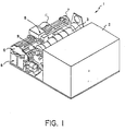
- Figure 1 illustrates schematically an exemplary ink jet printing apparatus 1 of one type that can advantageously utilize the present invention.
- the apparatus 1 comprises a paper feed and return sector 2 from which sheets are transported into and out of operative relation on printing cylinder 3.
- the detail structure of the sheet handling components do not constitute a part of the present invention and need not be described further.
- a print head assembly 5 which is mounted for movement on carriage assembly 6 by appropriate drive means 7. During printing operation the print head assembly is traversed across a print path in closely spaced relation to a print sheet which is rotating on cylinder 3.
- Ink is supplied to and retumed from the print head assembly by means of flexible conduits 11 which are couoled to ink cartridge 8.
- a storage and start-up station 9 is constructed adjacent the left side (as viewed in Fig. 1) of the operative printing path of print head assembly 5 and the drive means 7 and carriage assembly 6 are constructed to transport the print head assembly into operative reiations with station 9 at appropriate sequences of the operative cycle of apparatus 1 as will be described subsequently.
- the assembly 5 includes an upper print head portion including a print head body 21 mounted on housing 22 and having an inlet 23 for receiving ink.
- the body 21 has a passage leading to a print head cavity 24 and an outlet 29 (see Fig. 3) leading from the cavity 24 to an ink circulation system of apparatus 1.
- the upper print head portion also includes an orifice plate 25 and suitable transducer means (not shown) for imparting mechanical vibration to the body 21.
- Such transducer can take various forms known in the art for producing periodic perturbations of the ink fiiament(s) issuing from the orifice piate 25 to assure break-up of the ink filaments into streams of uniformly soaced ink droplets.
- Preferred orifice plate constructions for use in accord with the present invention are disclosed in U.S. Patent 4 184 925 ; however, a variety of other orifice constructions are useful.
- the lower portion of print head assembly 5 includes a charge plate 26 constructed to impart desired charge upon ink droplets at the point of filament break-u p and a drop catcher configuration 27 that is constructed and located to catch non-printing droplets (in this arrangement charged droplets).
- a charge plate 26 constructed to impart desired charge upon ink droplets at the point of filament break-u p
- a drop catcher configuration 27 that is constructed and located to catch non-printing droplets (in this arrangement charged droplets).
- Exemplary preferred charge plate constructions are disclosed in U.S. Application serial No. 517 608, entitled « Molded Charge Eiectrode Structure and filed July 27, 1983 and in U.S. Patent 4 223 321 ; however, other charge plate constructions are useful in accord with the present invention.
- Exemplary catcher configurations are described in U.S. Patents 3 813 675 ; 4 035 811 and 4 268 836 ; again other constructions are useful.
- the lower print head assembly includes a predeterminedly configured and located wail member 28 which provides protection and air control functions for the printer apparatus.
- the gap between the wall 28 and catcher 27 can be 0,76 Millimeter (0.3 inches) or closer so that the ink jet streams pass therebetween in close proximity to the wall surfaces.
- the ink supply and circulation system of the Fig. 1 apparatus inciudes various ink conduits (i. e. lines) which form an ink recirculation path.
- pump inlet line 71 extends from ink supply cartridge 8 to the inlet of pump 60
- outlet line 72 extends between pump 60 and a main filter 69
- head supply line 73 extends from main filter 69 to the print head inlet
- head return line 74 extends from the print head outlet to a junction between catcher return line 75 and the main ink return line 76.
- An ink return line 79 also extends from station 9 back to cartridge 8.
- An air bleed line 78 extends from main filter 61 back to cartridge 8 and an ink bypass line 77 extends from a juncture with line 73 also back to cartridge 8.
- the Fig. 3 system also includes an ink heater 61, a flow restrictor 62, final filter 63, head return valve 64, temperature sensor 65 and pressure sensor 66.
- the present invention is not limited to use with the particular ink circulation line arrangement illustrated in Fig. 3.
- cartridge 8 can be in a form that is constructed to be readily inserted and removed, as a unit, from operative relation with lines of the ink circulation system.
- suitable couplings 41 a. 41 b, 41 c. 41 d and 41 e are formed on the cartridge 8 in a manner so as to operatively connect with lines 71, 76, 77, 78 and 79 upon insertion of the ink cartridge 8 into its mounting in the printer apparatus.
- Cartridge 8 can have a vent 42 to render the main interior thereof at atmospheric pressure.
- the cartridge can be constructed with an internal venturi structure which effects return of ink from return line 76.
- the present invention can function equally well in a circulation system utilizing a separate vacuum pump to withdraw ink from the return lines back to the cartridge.
- Heater 61 under the feedback control of sensor(s) 65, conditions the circulating ink to the proper operating temperature and pressure sensor 66 regulates pump 60 to attain the proper ambient line circulation pressure.
- valve 64 When valve 64 is closed, ink passing into the print head 21 issues as ink streams from the orifice plate 25 of the print head. The ink streams will break into droplets either in an uncontrolled manner or in a controlled manner under the influence of a stimulating transducer as subsequently described.
- a resistance heater 50 is provided within the interior of catcher 27 at a location where its thermal energy can be readily conducted to raise the temperature of : (1) portions of the catcher surface 27b that are adjacent the droplet stream passing from orifice plate 25 to print substrate S and (2) the exposed surfaces of charge plate 26.
- heater element is affixed in a cavity 51 by means of s thermally conductive adhesive 52.
- the main body of the catcher is preferably formed of stainless steel or filled plastic; however, other material having a good thermal conductivity can be used in accord with this embodiment of the present invention.
- a spacer element 53 e. g. plastic shim material, is provided in an interior region between the charge plate 26 and catcher 27 and a plastic potting material, e. g. and epoxy resin, 54 couples the top of the catcher with charge plate 26.
- a spacer element 53 e. g. plastic shim material
- a plastic potting material e. g. and epoxy resin
- Figure 5 is a front view of the lower print head assembly illustrating in hidden lines the circuit leads 56, 57 for the resistive heater 50 and diagrammatically the switch 58 that operates under control of machine control 100 to selectively energize the power source P for the heater 50. If desired a temperature sensor 59 is coupled to the catcher to provide an input to control 100 that maintains the heated surfaces of the print head assembly at the proper temperature. Altema- tively the heater can operate at a predeterminedly fixed power level.
- the heater operate to maintain the print head surfaces at the minimum temperature that will reliably insure that contiguous vapor does not condense on them.
- This minimum temperature will depend upon the nominal operating ink temperature, the spacing between the ink jet streams and the charge plate and catcher surfaces and the ambient humidity and temperature. In general, it should be above the dew point of the region around the ink jet streams. In one preferred embodiment with an issuing ink temperature of about 85°F, heating that raised the portions of the catcher surface to temperatures of 106°F and 110°F was found sufficient to prevent condensation on both the catcher and charge plate. Smaller temperature differentials can be utilized and one skilled in the art can determine operable temperature differentials by visual observation while changing the applied heating power.
- heating means illustrated and described above is highly advantageous for ink jet printing apparatus wherein the print head is traversed with respect to a print substrate.
- other means for preventing condensation of ink vapors during printing operation can be used in accord with the concept of the invention.
- radiant heating means located to direct energy to the pertinent surfaces can be used in some apparatus constructions.
- means for providing a heated air stream across the pertinent surfaces can be utilized.
- Other implementations will occur to those skilled in the art.
- the present invention is useful to provide more reliable and higher quality ink jet printing by reducing or eliminating the detrimental effects, on printing ink droplets, of liquid build-up on the charge plate and catcher.
Abstract
Description
- The present invention relates to ink jet printing apparatus of the type having means for generating an ink droplet stream(s) from ink supplied thereto, a charge plate having an electrode(s) for selectively imparting electrical charge to droplets of such stream(s) and catcher means for catching a portion of such droplets in response to the charging or non-charging thereof.
- The term « continuous has been used in the field of ink jet printer apparatus to characterize the types of ink jet printers that utilize continuous streams of ink droplets, e. g. in distinction to the « drop on demand types. Continuous ink jet printers can be of the binary type (having « catch and « print trajectories for droplets of the continuous streams) and of the muiti-defiec- tion type (having a plurality of print trajectories for droplets of the continuous streams). Binary type apparatus most often employs a plurality of droplet streams while muitidefiection apparatus most often employs a single droplet stream.
- In general, continuous ink jet printing apparatus have an ink cavity to which ink is supplied under pressure so as to issue in a stream from an orifice plate that is in liquid communication with the cavity. Periodic perturbations are imposed on the liquid stream (e. g. vibrations by an electro-mechanical transducer) to cause the stream to break up into uniformly sized and shaped droplets. A charge plate is located proximate the stream break-off point to impart electrical charge in accord with a print information signal and charged droplets are deflected from their nominal trajectory. In one common binary printing apparatus charged droplets are deflected into a catcher assembly and non-charged droplets proceed along their nominal trajectory to the print medium.
- The components described above (particularly the orifice plate and charge plate) must be precisely positioned to achieve proper charging, deflection and catching of non-print drops. Even after this is achieved, however, significant problems are presented at each operational start-up. For example, liquid accumulations on the charge plate can cause shorting or improper charging of droplets. Liquid accumulations at undesired locations on the catcher assembly can affect droplet deflection or impede droplet passage to the print medium.
- Sophisticated prior art techniques have been developed to avoid the occurrence of such unwanted liquid accumulations on critical surfaces of the print head assembly. For example, complicated routines have been developed for starting- up and shutting down the ink jet streams without depositing ink on the critical print head surfaces. Also, air purging cycles have been provided to remove ink that is undesirably deposited on those surfaces. In some instances it is necessary to stop operation and physically clean the critical print head surfaces.
- We have found that even when such procedures are meticulously practiced, malfunctions such as shorting of the drop charging electrodes and inconsistent droplet flights continue to appear at unacceptably short printing intervals. This problem was particularly severe with compact print head structures wherein the lower print head is located quite close to the ink jet printing streams.
- After considerable investigation we discovered that one significant cause of such malfunctioning is the build-up of a clear liquid on the critical surfaces of the print head assembly. By further studies we discovered the cause of such clear liquid accumulation and structural embodiments which eliminate it, thus markedly reducing the frequency of ink jet printing apparatus malfunctions.
- In this connection the US-Patent 4 245 226 discloses an ink jet printing apparatus including a deflection electrode which is heated in order to prevent drop condensation thereon.
- In contrast to this the inventive ink jet printing apparatus has the advantage of preventing condensation on both the catcher means and the charge plate.
- The purpose of the present invention is to improve the quality and reliability of ink jet printing apparatus, as well as decrease the maintenance required for such apparatus, by providing means for preventing the. undesired accumulation of liquid on critical surfaces of the print head assembly.
- One inventive constitution provides, in ink jet printing apparatus of the type having means for generating an ink droplet stream(s) from ink supplied thereto, a charge plate having an electrode(s) for selectively imparting electrical charge to droplets of such stream(s) and catcher means for catching a portion of such droplets in response to the charging or non-charging thereof. This apparatus is characterized in that the charge plate and the catcher means are physically coupled for conductive transfer of thermal energy and comprising heater means in the catcher means for heating the operative surfaces of both the charge plate. and the catcher means to a temperature preventing condensation of ink vapors.
- The subsequent description of preferred embodiments of the present invention refers to the attached drawings wherein:
- Figure 1 is a perspective view of one embodiment of ink jet printing apparatus in accord with the present invention;
- Figure 2 is a cross-sectional view of a portion of the Fig. 1 apparatus illustrating one embodiment of the upper and lower print head assemblies;
- Figure 3 is a diagrammatic illustration of the ink supply system of the apparatus shown in Fig. 1;
- Figure 4 is an enlarged cross-sectional view of a portion of the apparatus shown in Fig. 2; and
- Figure 5 is an enlarged frontal view of a portion of the apparatus shown in Fig. 2.
- Figure 1 illustrates schematically an exemplary ink jet printing apparatus 1 of one type that can advantageously utilize the present invention. In general, the apparatus 1 comprises a paper feed and
return sector 2 from which sheets are transported into and out of operative relation onprinting cylinder 3. The detail structure of the sheet handling components do not constitute a part of the present invention and need not be described further. Also illustrated generally in Fig. 1 is aprint head assembly 5 which is mounted for movement on carriage assembly 6 by appropriate drive means 7. During printing operation the print head assembly is traversed across a print path in closely spaced relation to a print sheet which is rotating oncylinder 3. Ink is supplied to and retumed from the print head assembly by means of flexible conduits 11 which are couoled toink cartridge 8. A storage and start-up station 9 is constructed adjacent the left side (as viewed in Fig. 1) of the operative printing path ofprint head assembly 5 and the drive means 7 and carriage assembly 6 are constructed to transport the print head assembly into operative reiations with station 9 at appropriate sequences of the operative cycle of apparatus 1 as will be described subsequently. - Referring to Fig. 2, one embodiment of
print head assembly 5 according to the present invention can be seen in more detail. Theassembly 5 includes an upper print head portion including aprint head body 21 mounted onhousing 22 and having aninlet 23 for receiving ink. Thebody 21 has a passage leading to aprint head cavity 24 and an outlet 29 (see Fig. 3) leading from thecavity 24 to an ink circulation system of apparatus 1. The upper print head portion also includes anorifice plate 25 and suitable transducer means (not shown) for imparting mechanical vibration to thebody 21. Such transducer can take various forms known in the art for producing periodic perturbations of the ink fiiament(s) issuing from theorifice piate 25 to assure break-up of the ink filaments into streams of uniformly soaced ink droplets. Preferred orifice plate constructions for use in accord with the present invention are disclosed in U.S. Patent 4 184 925 ; however, a variety of other orifice constructions are useful. - The lower portion of
print head assembly 5 includes acharge plate 26 constructed to impart desired charge upon ink droplets at the point of filament break-up and adrop catcher configuration 27 that is constructed and located to catch non-printing droplets (in this arrangement charged droplets). Exemplary preferred charge plate constructions are disclosed in U.S. Application serial No. 517 608, entitled « Molded Charge Eiectrode Structure and filed July 27, 1983 and in U.S. Patent 4 223 321 ; however, other charge plate constructions are useful in accord with the present invention. Exemplary catcher configurations are described in U.S.Patents 3 813 675 ; 4 035 811 and 4 268 836 ; again other constructions are useful. Finally, in this embodiment, the lower print head assembly includes a predeterminedly configured and locatedwail member 28 which provides protection and air control functions for the printer apparatus. In the preferred embodiment shown in Fig. 2. the gap between thewall 28 andcatcher 27 can be 0,76 Millimeter (0.3 inches) or closer so that the ink jet streams pass therebetween in close proximity to the wall surfaces. - The ink supply and circulation system of the Fig. 1 apparatus inciudes various ink conduits (i. e. lines) which form an ink recirculation path. As illustrated schematically in Fg. 3, pump inlet line 71 extends from
ink supply cartridge 8 to the inlet ofpump 60,outlet line 72 extends betweenpump 60 and a main filter 69,head supply line 73 extends from main filter 69 to the print head inlet andhead return line 74 extends from the print head outlet to a junction betweencatcher return line 75 and the mainink return line 76. Anink return line 79 also extends from station 9 back tocartridge 8. An air bleedline 78 extends frommain filter 61 back tocartridge 8 and an ink bypass line 77 extends from a juncture withline 73 also back tocartridge 8. The Fig. 3 system also includes anink heater 61, aflow restrictor 62,final filter 63,head return valve 64,temperature sensor 65 andpressure sensor 66. As will be clear from subsequent descriptions, the present invention is not limited to use with the particular ink circulation line arrangement illustrated in Fig. 3. - As shown in Figs. 1 and 3,
cartridge 8 can be in a form that is constructed to be readily inserted and removed, as a unit, from operative relation with lines of the ink circulation system. For this purpose suitable couplings 41 a. 41 b, 41 c. 41 d and 41 e are formed on thecartridge 8 in a manner so as to operatively connect withlines ink cartridge 8 into its mounting in the printer apparatus.Cartridge 8 can have avent 42 to render the main interior thereof at atmospheric pressure. The cartridge can be constructed with an internal venturi structure which effects return of ink fromreturn line 76. However, the present invention can function equally well in a circulation system utilizing a separate vacuum pump to withdraw ink from the return lines back to the cartridge. - '
Heater 61, under the feedback control of sensor(s) 65, conditions the circulating ink to the proper operating temperature andpressure sensor 66 regulatespump 60 to attain the proper ambient line circulation pressure. Whenvalve 64 is closed, ink passing into theprint head 21 issues as ink streams from theorifice plate 25 of the print head. The ink streams will break into droplets either in an uncontrolled manner or in a controlled manner under the influence of a stimulating transducer as subsequently described. - Referring again to Fig. 2, one preferred construction for preventing the accumulation of undesired liquid on operative surfaces of the lower print head is shown. Specifically, a
resistance heater 50 is provided within the interior ofcatcher 27 at a location where its thermal energy can be readily conducted to raise the temperature of : (1) portions of thecatcher surface 27b that are adjacent the droplet stream passing fromorifice plate 25 to print substrate S and (2) the exposed surfaces ofcharge plate 26. The details of this construction are shown more clearly in Fig. 4 and it can be seen that heater element is affixed in acavity 51 by means of s thermallyconductive adhesive 52. The main body of the catcher is preferably formed of stainless steel or filled plastic; however, other material having a good thermal conductivity can be used in accord with this embodiment of the present invention. - In the embodiment shown in Fig. 4 a
spacer element 53, e. g. plastic shim material, is provided in an interior region between thecharge plate 26 andcatcher 27 and a plastic potting material, e. g. and epoxy resin, 54 couples the top of the catcher withcharge plate 26. Thus, both surface 26a (which bears electrode leads) andsurface 26b (which bears the drop charging electrodes) are heatable byheater 50 to a selected temperature above ambient. - Figure 5 is a front view of the lower print head assembly illustrating in hidden lines the circuit leads 56, 57 for the
resistive heater 50 and diagrammatically theswitch 58 that operates under control ofmachine control 100 to selectively energize the power source P for theheater 50. If desired atemperature sensor 59 is coupled to the catcher to provide an input to control 100 that maintains the heated surfaces of the print head assembly at the proper temperature. Altema- tively the heater can operate at a predeterminedly fixed power level. - In this regard, it is preferred that the heater operate to maintain the print head surfaces at the minimum temperature that will reliably insure that contiguous vapor does not condense on them. This minimum temperature will depend upon the nominal operating ink temperature, the spacing between the ink jet streams and the charge plate and catcher surfaces and the ambient humidity and temperature. In general, it should be above the dew point of the region around the ink jet streams. In one preferred embodiment with an issuing ink temperature of about 85°F, heating that raised the portions of the catcher surface to temperatures of 106°F and 110°F was found sufficient to prevent condensation on both the catcher and charge plate. Smaller temperature differentials can be utilized and one skilled in the art can determine operable temperature differentials by visual observation while changing the applied heating power.
- The embodiment of heating means illustrated and described above is highly advantageous for ink jet printing apparatus wherein the print head is traversed with respect to a print substrate. However, other means for preventing condensation of ink vapors during printing operation can be used in accord with the concept of the invention. For example, radiant heating means located to direct energy to the pertinent surfaces can be used in some apparatus constructions. Also means for providing a heated air stream across the pertinent surfaces can be utilized. Other implementations will occur to those skilled in the art.
- While the invention has been described with respect to continuous ink jet printing apparatus and the prevention of condensation on the charge plate and/or catcher surfaces thereof, it has application to other ink jet printers (e. g. drop on demand printers) and to the prevention of condensate accumulation on other structures (e. g. protective wall structure such as shown at 28 in Fig. 2). Thus, a heater element such as shown at 50' in Fig. 2 can also be provided in such other lower print head structure.
- The present invention is useful to provide more reliable and higher quality ink jet printing by reducing or eliminating the detrimental effects, on printing ink droplets, of liquid build-up on the charge plate and catcher.
Claims (3)
Applications Claiming Priority (2)
| Application Number | Priority Date | Filing Date | Title |
|---|---|---|---|
| US06/722,547 US4622562A (en) | 1985-04-12 | 1985-04-12 | Ink jet printhead multi-component heating |
| US722547 | 1985-04-12 |
Publications (2)
| Publication Number | Publication Date |
|---|---|
| EP0217872A1 EP0217872A1 (en) | 1987-04-15 |
| EP0217872B1 true EP0217872B1 (en) | 1990-03-28 |
Family
ID=24902310
Family Applications (1)
| Application Number | Title | Priority Date | Filing Date |
|---|---|---|---|
| EP86902260A Expired - Lifetime EP0217872B1 (en) | 1985-04-12 | 1986-04-09 | Print head heating for ink jet printer apparatus |
Country Status (6)
| Country | Link |
|---|---|
| US (1) | US4622562A (en) |
| EP (1) | EP0217872B1 (en) |
| JP (1) | JPH0624873B2 (en) |
| CA (1) | CA1255535A (en) |
| DE (1) | DE3669843D1 (en) |
| WO (1) | WO1986006028A1 (en) |
Families Citing this family (8)
| Publication number | Priority date | Publication date | Assignee | Title |
|---|---|---|---|---|
| DE3877291T2 (en) * | 1987-09-03 | 1993-05-27 | Matsushita Electric Ind Co Ltd | INK-JET RECORDING DEVICE. |
| US4937589A (en) * | 1989-08-23 | 1990-06-26 | Eastman Kodak Company | Continuous ink jet print heads |
| EP0744291B1 (en) * | 1995-05-26 | 2000-07-12 | SCITEX DIGITAL PRINTING, Inc. | Charge plate fabrication process |
| US5739829A (en) * | 1996-04-30 | 1998-04-14 | Scitex Digital Printing, Inc. | Bubble flow detection |
| DE69701920T2 (en) * | 1996-04-30 | 2000-12-07 | Scitex Digital Printing Inc | Lip heater for continuous inkjet printer |
| US6848767B2 (en) * | 2002-10-04 | 2005-02-01 | Eastman Kodak Company | Automatic startup for a solvent ink printing system |
| US7163281B2 (en) | 2004-05-05 | 2007-01-16 | Eastman Kodak Company | Method for improving drop charging assembly flatness to improved drop charge uniformity in planar electrode structures |
| US8976410B2 (en) | 2013-04-04 | 2015-03-10 | Hewlett-Packard Development Company, L.P. | Temporarily reducing throughput of a printing system |
Family Cites Families (5)
| Publication number | Priority date | Publication date | Assignee | Title |
|---|---|---|---|---|
| JPS5525066B2 (en) * | 1974-10-30 | 1980-07-03 | ||
| DE2659398A1 (en) * | 1976-12-29 | 1978-07-06 | Siemens Ag | HEATING DEVICE FOR WRITING HEADS IN INK MOSAIC WRITING DEVICES |
| US4106030A (en) * | 1977-02-14 | 1978-08-08 | Recognition Equipment Incorporated | Ink jet printer ink heater |
| US4245226A (en) * | 1979-07-06 | 1981-01-13 | The Mead Corporation | Ink jet printer with heated deflection electrode |
| JPS57103850A (en) * | 1980-12-19 | 1982-06-28 | Ricoh Co Ltd | Ink jet printer |
-
1985
- 1985-04-12 US US06/722,547 patent/US4622562A/en not_active Expired - Lifetime
-
1986
- 1986-03-26 CA CA000505132A patent/CA1255535A/en not_active Expired
- 1986-04-09 EP EP86902260A patent/EP0217872B1/en not_active Expired - Lifetime
- 1986-04-09 WO PCT/US1986/000703 patent/WO1986006028A1/en active IP Right Grant
- 1986-04-09 JP JP61501907A patent/JPH0624873B2/en not_active Expired - Fee Related
- 1986-04-09 DE DE8686902260T patent/DE3669843D1/en not_active Expired - Lifetime
Also Published As
| Publication number | Publication date |
|---|---|
| EP0217872A1 (en) | 1987-04-15 |
| CA1255535A (en) | 1989-06-13 |
| DE3669843D1 (en) | 1990-05-03 |
| US4622562A (en) | 1986-11-11 |
| JPS62500445A (en) | 1987-02-26 |
| JPH0624873B2 (en) | 1994-04-06 |
| WO1986006028A1 (en) | 1986-10-23 |
Similar Documents
| Publication | Publication Date | Title |
|---|---|---|
| EP0216912B1 (en) | Method for ink jet print head cleaning | |
| CA1257503A (en) | Ink jet printing apparatus having ultrasonic print head cleaning system | |
| EP0217932B1 (en) | Print head protection for ink jet printers | |
| US5574485A (en) | Ultrasonic liquid wiper for ink jet printhead maintenance | |
| US5528271A (en) | Ink jet recording apparatus provided with blower means | |
| EP0216911B1 (en) | Ink jet printing apparatus having an improved start-up system | |
| EP0217872B1 (en) | Print head heating for ink jet printer apparatus | |
| EP0216913B1 (en) | Ink jet printing apparatus having a wet-storage system | |
| US4591873A (en) | Ink jet printing apparatus with orifice array cleaning system | |
| WO1998017476A1 (en) | Apparatus and method for multi-jet generation of high viscosity fluid | |
| US20040109054A1 (en) | Ink jet printer having a dual function air cooling and drying system | |
| EP0521345B1 (en) | Continuous ink jet catcher device having improved flow control construction | |
| US4340895A (en) | Degassing ink supply apparatus for ink jet printer | |
| EP0561205B1 (en) | Continuous ink jet catcher with improved screen structure | |
| CA2124988C (en) | Ink jet image drier | |
| EP0306341B1 (en) | Ink jet recording apparatus | |
| US6280013B1 (en) | Heat exchanger for an inkjet printhead | |
| GB2377671A (en) | Method for detecting and determining ink droplet trajectories using a plurality of proximity sensors contained within a housing | |
| US4929966A (en) | Continuous ink jet printer with a gravity drain, catcher return system | |
| JP4086919B2 (en) | Inkjet print cartridge and method of manufacturing the same | |
| EP0805030A2 (en) | Lid heater for a continuous ink-jet printer | |
| US4591874A (en) | Ink jet printing apparatus having improved home station diagnostic system | |
| EP1742800B1 (en) | Inkjet print station | |
| JP2795740B2 (en) | Ink jet recording device | |
| JPH03187753A (en) | Recorder |
Legal Events
| Date | Code | Title | Description |
|---|---|---|---|
| PUAI | Public reference made under article 153(3) epc to a published international application that has entered the european phase |
Free format text: ORIGINAL CODE: 0009012 |
|
| AK | Designated contracting states |
Kind code of ref document: A1 Designated state(s): DE FR GB IT SE |
|
| 17P | Request for examination filed |
Effective date: 19870327 |
|
| 17Q | First examination report despatched |
Effective date: 19880816 |
|
| GRAA | (expected) grant |
Free format text: ORIGINAL CODE: 0009210 |
|
| AK | Designated contracting states |
Kind code of ref document: B1 Designated state(s): DE FR GB IT SE |
|
| PG25 | Lapsed in a contracting state [announced via postgrant information from national office to epo] |
Ref country code: IT Free format text: LAPSE BECAUSE OF FAILURE TO SUBMIT A TRANSLATION OF THE DESCRIPTION OR TO PAY THE FEE WITHIN THE PRESCRIBED TIME-LIMIT;WARNING: LAPSES OF ITALIAN PATENTS WITH EFFECTIVE DATE BEFORE 2007 MAY HAVE OCCURRED AT ANY TIME BEFORE 2007. THE CORRECT EFFECTIVE DATE MAY BE DIFFERENT FROM THE ONE RECORDED. Effective date: 19900328 Ref country code: SE Effective date: 19900328 |
|
| REF | Corresponds to: |
Ref document number: 3669843 Country of ref document: DE Date of ref document: 19900503 |
|
| ET | Fr: translation filed | ||
| K2 | Correction of patent specification published | ||
| PLBE | No opposition filed within time limit |
Free format text: ORIGINAL CODE: 0009261 |
|
| STAA | Information on the status of an ep patent application or granted ep patent |
Free format text: STATUS: NO OPPOSITION FILED WITHIN TIME LIMIT |
|
| 26N | No opposition filed | ||
| REG | Reference to a national code |
Ref country code: GB Ref legal event code: 732E |
|
| REG | Reference to a national code |
Ref country code: FR Ref legal event code: TP |
|
| REG | Reference to a national code |
Ref country code: GB Ref legal event code: IF02 |
|
| REG | Reference to a national code |
Ref country code: GB Ref legal event code: 732E |
|
| REG | Reference to a national code |
Ref country code: FR Ref legal event code: TP |
|
| PGFP | Annual fee paid to national office [announced via postgrant information from national office to epo] |
Ref country code: GB Payment date: 20050314 Year of fee payment: 20 |
|
| PGFP | Annual fee paid to national office [announced via postgrant information from national office to epo] |
Ref country code: FR Payment date: 20050401 Year of fee payment: 20 |
|
| PGFP | Annual fee paid to national office [announced via postgrant information from national office to epo] |
Ref country code: DE Payment date: 20050429 Year of fee payment: 20 |
|
| REG | Reference to a national code |
Ref country code: GB Ref legal event code: PE20 |
|
| PG25 | Lapsed in a contracting state [announced via postgrant information from national office to epo] |
Ref country code: GB Free format text: LAPSE BECAUSE OF EXPIRATION OF PROTECTION Effective date: 20060408 |