EP0217833B1 - Sealing control method for receptables and sealing control installation therefor - Google Patents
Sealing control method for receptables and sealing control installation therefor Download PDFInfo
- Publication number
- EP0217833B1 EP0217833B1 EP86901769A EP86901769A EP0217833B1 EP 0217833 B1 EP0217833 B1 EP 0217833B1 EP 86901769 A EP86901769 A EP 86901769A EP 86901769 A EP86901769 A EP 86901769A EP 0217833 B1 EP0217833 B1 EP 0217833B1
- Authority
- EP
- European Patent Office
- Prior art keywords
- container
- temperature
- time
- measured
- pressure value
- Prior art date
- Legal status (The legal status is an assumption and is not a legal conclusion. Google has not performed a legal analysis and makes no representation as to the accuracy of the status listed.)
- Expired - Lifetime
Links
- 238000000034 method Methods 0.000 title claims abstract description 39
- 238000007789 sealing Methods 0.000 title abstract 4
- 238000009434 installation Methods 0.000 title 1
- 238000005259 measurement Methods 0.000 claims abstract description 38
- 238000012360 testing method Methods 0.000 claims description 79
- 238000012937 correction Methods 0.000 claims description 31
- 238000009529 body temperature measurement Methods 0.000 claims description 23
- 230000005855 radiation Effects 0.000 claims description 18
- 230000035945 sensitivity Effects 0.000 claims description 8
- 238000012935 Averaging Methods 0.000 claims description 7
- 230000001960 triggered effect Effects 0.000 claims description 6
- 238000004364 calculation method Methods 0.000 claims description 2
- 238000002474 experimental method Methods 0.000 claims 1
- 239000011796 hollow space material Substances 0.000 claims 1
- 230000006870 function Effects 0.000 description 27
- 238000004088 simulation Methods 0.000 description 19
- 239000003570 air Substances 0.000 description 11
- 238000009530 blood pressure measurement Methods 0.000 description 9
- 238000004519 manufacturing process Methods 0.000 description 6
- 238000010586 diagram Methods 0.000 description 4
- 238000005516 engineering process Methods 0.000 description 4
- 239000000463 material Substances 0.000 description 4
- 230000003247 decreasing effect Effects 0.000 description 2
- 238000009826 distribution Methods 0.000 description 2
- 238000007373 indentation Methods 0.000 description 2
- 238000005070 sampling Methods 0.000 description 2
- 239000012080 ambient air Substances 0.000 description 1
- 230000005540 biological transmission Effects 0.000 description 1
- 230000015572 biosynthetic process Effects 0.000 description 1
- 230000036760 body temperature Effects 0.000 description 1
- 238000010276 construction Methods 0.000 description 1
- 239000012611 container material Substances 0.000 description 1
- 238000010924 continuous production Methods 0.000 description 1
- 230000001419 dependent effect Effects 0.000 description 1
- 238000013461 design Methods 0.000 description 1
- 238000011156 evaluation Methods 0.000 description 1
- 230000005284 excitation Effects 0.000 description 1
- 238000013213 extrapolation Methods 0.000 description 1
- 230000010354 integration Effects 0.000 description 1
- 238000000691 measurement method Methods 0.000 description 1
- 238000012544 monitoring process Methods 0.000 description 1
- 238000009659 non-destructive testing Methods 0.000 description 1
- 238000012545 processing Methods 0.000 description 1
- 238000003908 quality control method Methods 0.000 description 1
- 230000009131 signaling function Effects 0.000 description 1
- 238000004381 surface treatment Methods 0.000 description 1
- 230000002123 temporal effect Effects 0.000 description 1
- 238000012546 transfer Methods 0.000 description 1
- 239000002699 waste material Substances 0.000 description 1
Images


Classifications
-
- G—PHYSICS
- G01—MEASURING; TESTING
- G01M—TESTING STATIC OR DYNAMIC BALANCE OF MACHINES OR STRUCTURES; TESTING OF STRUCTURES OR APPARATUS, NOT OTHERWISE PROVIDED FOR
- G01M3/00—Investigating fluid-tightness of structures
- G01M3/002—Investigating fluid-tightness of structures by using thermal means
-
- G—PHYSICS
- G01—MEASURING; TESTING
- G01M—TESTING STATIC OR DYNAMIC BALANCE OF MACHINES OR STRUCTURES; TESTING OF STRUCTURES OR APPARATUS, NOT OTHERWISE PROVIDED FOR
- G01M3/00—Investigating fluid-tightness of structures
- G01M3/02—Investigating fluid-tightness of structures by using fluid or vacuum
- G01M3/26—Investigating fluid-tightness of structures by using fluid or vacuum by measuring rate of loss or gain of fluid, e.g. by pressure-responsive devices, by flow detectors
- G01M3/32—Investigating fluid-tightness of structures by using fluid or vacuum by measuring rate of loss or gain of fluid, e.g. by pressure-responsive devices, by flow detectors for containers, e.g. radiators
- G01M3/3236—Investigating fluid-tightness of structures by using fluid or vacuum by measuring rate of loss or gain of fluid, e.g. by pressure-responsive devices, by flow detectors for containers, e.g. radiators by monitoring the interior space of the containers
Definitions
- the present invention relates to a method for checking the density of containers, in which a container is pressurized or evacuated and a pressure quantity is measured, as a leakage measurement indication, and a limit pressure quantity for the decision as to whether a container is rated as leaky or leaky , specifies and further shifted in time from the measurement of the pressure size, a size that is significant for the then prevailing container temperature is measured and a size derived therefrom is used as a correction of the measured pressure size.
- a quantity referred to below as the "pressure quantity” can be a pressure difference, an absolute pressure or a quantity derived from such, such as mechanical deformation, etc.
- the invention relates to a density test device for containers with a test station, in which a pressure quantity that is significant for a container leakage is measured, and with a measuring device for a quantity that is significant for the container temperature, the measured pressure quantity, taking into account the quantity that is significant for the container temperature, with a Limit pressure size is compared for a decision whether a container is leaky or leaky.
- Containers are now manufactured at great speed. This applies particularly to welded cans.
- the increasing production speed on the one hand and the use of increasingly thin-walled material on the other hand require high precision in the manufacturing process so that a high density of the containers is guaranteed.
- a high density is also required within a filling line, i.e. from the point of view of the can processor, so that food does not spoil, environmentally unfriendly or very valuable materials do not leak out of the containers.
- Both the manufacturers and the processors of such containers rely on well-functioning, reliable quality control. Smallest leaks or leaks must be able to be detected. This high requirement for density testing can already be met today.
- the density can be checked in different ways.
- the container is either pressurized or pressurized by air or another gas. If there is a leak, air or gas then flows into or out of the environment, as a result of which the internal pressure of the container changes.
- the internal pressure of the container is observed, i.e. the internal pressure difference in the container is registered within a predetermined period of time and compared with a change in the limit pressure that occurs in a container that has the largest still tolerable leak. If the measured change in internal pressure is greater than the predetermined limit pressure difference, the container is registered as a reject. A change in the internal pressure of the container is thus observed as the pressure variable.
- the container to be tested is enclosed in an autoclave. The air that flows out of the container to be tested flows into the autoclave and increases the pressure there, which in turn is registered. A change in the pressure in the container environment is thus registered here as the pressure variable.
- the containers are checked for density either after they have been manufactured or after they have been filled. In both cases, depending on the previous manufacturing process, they have undefined temperatures. This temperature does not only vary from. Plant to plant, but also within a plant in the same place. The reasons for the temperature scatter can be the processing of different containers or a variable production speed, a variable ambient temperature at different locations or a different container material. It is also conceivable that, due to a fault in the production line, the latter has to be stopped and then started again in such a way that the containers to be checked are produced at different temperatures at the same point on the production line. At the time of the density check of the containers, the container temperature does not always have to be the same. Even if the ambient temperature is kept constant within relatively narrow tolerances, the container temperature is not always the same, because the latter does not yet need to be thermally balanced with the surroundings at the density test point.
- the can is rated as a waste at an increased temperature, although this is not the case: the increased leakage rate is due to the temperature-related increased internal pressure.
- JP-A-58 216 926 also suggests the simultaneous measurement of pressure and temperature, which entails the above-mentioned disadvantages with regard to the construction effort.
- JP-A-59 206 737 and US-A-3 065 324, DE-A-2 829 154 and US ⁇ A ⁇ 3 579 775 describe special temperature measuring arrangements and methods.
- the present invention aims to provide a method or a density testing device of the above-mentioned type in which the disadvantages mentioned are eliminated, i.e. the test station is only occupied as long as this is necessary for the leakage significant pressure measurement and at the same time no additional measurement sensors are to be provided at the test station.
- the temperature measurement is thus carried out before or after the density test.
- the measured temperature cannot be used directly for pressure quantity correction purposes, but only after the temperature in the period of the density test has been inferred by temporal forward or backward extrapolation, which requires prior knowledge or identification of the thermal behavior of the container. Only after concluding the temperature during the density test can the latter again be applied in a corrective manner to one or the other of the pressure variables.
- thermal time behavior of the container be determined, therefrom determines the temperature of the container in the period of the pressure measurement according to the wording of claim 3.
- the temperature dependency of the limit pressure variable or the measured pressure variable is taken into account either after the container temperature is present in the time period of the pressure variable measurement according to the wording of claim 4, or that this dependency is stored as a function of the independent variable "temperature" and with the specific container temperature the function is included in the measurement of the pressure size, according to the wording of claim 5.
- the thermal time behavior of the container is measured from at least one container temperature and predetermined determination of the thermal container time constant - the latter mathematically, taking into account the time constant of the container and / or filling medium parameters, or experimentally Wording of claim 7 - determined.
- thermal time behavior of the containers particularly in the case of a variable container type, can be changed by identifying the thermal time behavior of the container from time-shifted measurements of container temperatures, taking into account the measurement time interval according to the wording of claim 8.
- the temperature measurement becomes less susceptible to noise by carrying out it by averaging several measurements over the measurement time.
- the container temperature is carried out by measuring the thermal radiation from the container cavity before measuring the pressure size and before closing the container, as a measurement of the integral thermal energy state of the container . It has been shown that the container cavity acts like a black body and the temperature radiation from this cavity is already the representative, i.e. mean temperature. This measurement takes into account locally different inside and outside surfaces, materials, etc.
- the last-mentioned procedure is extraordinarily simple, in particular in the case of a relative movement of the container and the temperature measuring arrangement, in which case the change in the detected radiation when the container opening enters the sensitivity range of the arrangement is used as a criterion for when the arrangement measures representative.
- the change in the detected radiation when the container opening enters the sensitivity range of the arrangement is used as a criterion for when the arrangement measures representative.
- use is made of the fact that the detected thermal radiation is significantly different, depending on whether the detector of the arrangement detects the radiation if there is no container cavity opposite, or if this is the case.
- This change is used directly to determine when the detector output signal is representative of the container temperature, i.e. when this output signal is to be processed further.
- the measuring device is now connected to an input of a correction unit at the output of the density test device, at the output of which a signal appears as a function of the signal at the input, the output of the correction unit preferably being connected to an input of a comparison unit, with a second input, to which a further signal is supplied to the latter, which corresponds to the measured pressure value representative of the container leakage.
- the correction unit comprises a computing unit.
- an output of the measuring device is routed to an input of a time function unit, that a switching element is provided which indicates that the density test is being carried out, the switching element then triggering the reading of the output signal of the time function unit, and the output signal of the time function unit, corresponding to the container temperature when the switching element is triggered, is led to the input of the correction unit.
- a temperature function that corresponds to the thermal behavior of the container is thus started with the temperature measurement and the prevailing time function value is read out when the density test is carried out.
- the time function unit comprises an arithmetic unit with an input device for inputting container and / or filling medium parameters, and that it calculates and preferably the thermal time constant of the container. at least when the switching element is triggered from the signal at the input of the time function unit as the initial value of the time constant, the value of a time function is calculated and output at the time of triggering.
- the measuring device outputs a measured value at at least two times and the time function unit identifies the thermal time behavior of the container, in particular its time constant, from the measured values and the time difference of their occurrence; the time function unit then simulates this behavior with at least one temperature measured value as a base value.
- the switching element then switches an output of the time function unit to the correction unit, with a signal value representative of the container temperature during the density test in the test station.
- the measuring device take several measurements, as sampled, at immediately successive times, and that it is followed by a time average unit whose output signal is further processed as a temperature measurement value signal in the sense mentioned, according to claim 19.
- the temperature measuring arrangement comprises a plurality of sensors, the outputs of which are fed to an average value unit, the output signal of which is in turn processed.
- a temperature measurement representative of the container is carried out in a very simple manner in accordance with claim 21, in that the measuring device comprises a radiation sensor which is arranged relative to the container in such a way that its opening lies in its sensitivity range and it is , With relative movement of the container and sensor, a position detector is preferably provided, which then forwards the sensor output as a temperature-representative signal when the container opening is in the sensitivity range of the sensor. With little additional effort, this is further achieved according to claim 22 in that the position detector comprises the sensor itself, which is followed by a threshold value unit, which then passes the sensor output on when the output signal of the sensor reaches its threshold value.
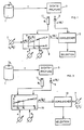
- FIG. 1 A first variant of the proposed method or the corresponding device is shown in FIG. 1 using a block diagram.
- a container 1 to be tested for density is subjected to a test pressure with regard to its surroundings Po.
- the container is then fed to a density test station 3 of a known type over an indefinite period of time T.
- the result of the density test at the time is a pressure variable p at temperature 8 measured with a sensor arrangement 5, in the time period of the density test, ie at time t.
- the pressure variable p which is measured in the density test, is, for example, the internal container pressure still prevailing after the time T has elapsed, both based on the ambient pressure, or if the container 1 is introduced into an autoclave during the density test, p is, for example, the then pressure in the autoclave.
- the technique used to carry out the density test, ie which pressure variable p is observed, is immaterial in the context of the present invention. It is essential that the pressure test p (6 1 ) is available directly or indirectly as a result of the density test.
- the measured pressure variable p (6 1 ) as a measure of the leakage must now be compared with a corresponding, predetermined pressure variable PG , i.e. it must be determined whether the measured pressure variable is larger or smaller than said limit value in order to decide whether the container can be described as tight or leaking.
- the limit pressure variable p G based on a temperature 8 2 at which the limit pressure variable PG has been specified, deviates.
- the density test temperature ⁇ 1 measured with a temperature sensor 11 is also fed to the correction unit 9.
- the latter basically works as a function generator and takes into account the linear approximation, at least in the first approximation Dependence between pressure p and temperature 8, with constant volume.
- the temperature ⁇ 1 in the time period t of the density test is again measured, and the measured pressure p is measured on a correction unit 15, taking into account the linear dependence between pressure and temperature at constant volume at least in the first approximation ; measured at the temperature ⁇ 1 , corrected to the previously known temperature 0 2 at which the limit pressure variable p G was specified on the specification unit 7.
- the correction units 9 and 15 can be implemented very simply, for example, in an analog design.
- FIG. 3 shows a simple circuit for realizing the correction unit 9.
- a signal corresponding to temperature 8 during the density test is fed to a first amplifier 15, with gain 1, from which the difference between this signal and a predetermined signal corresponding to temperature 6 2 is formed.
- the latter corresponds to the temperature at which the limit pressure variable p G was specified.
- the input of a further amplifier 17 is fed with the output signal corresponding to this temperature difference ⁇ 2 ⁇ 1 , the gain of which is set in accordance with the characteristic slope a.
- a possible structure of the correction unit 15 is shown in FIG. 4 analogously to FIG.
- a difference signal corresponding to the difference in temperature 8, in the density test and in temperature 8 2 , at which the limit pressure variable P G is predetermined, is formed on a first amplifier 19.
- it has a gain of 1 and a value corresponding to the temperature 8 2 is input to it.
- the output signal corresponding to this temperature difference ( ⁇ 2 ⁇ 1 ) is fed to a further amplifier circuit 21, the gain of which corresponds to the characteristic slope a.
- the "offset" signal of the amplifier circuit 21 is correspondingly signaled by the output of the pressure sensor 5 from FIG the measured pressure variable p (8 1 ).
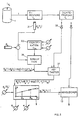
- FIG. 5 shows a method that differs from the method shown in principle with reference to FIGS. 1 and 2.
- the temperature ⁇ 1 is measured at the moment t, the density test or in a time period before or after the density test, which is irrelevant with regard to the rapidity of thermal changes in the container.
- the aim should often be to separate the temperature measurement and the density test from time to place. If this is done, the temperature measurement on the container does not give the temperature that prevails during the density test of the container. Taking into account the time period between the temperature measurement and the density test, the temperature of the container at the beginning or at the end of this period must be used to infer the container temperature at the end or at the beginning of this time period, ie during the density test.
- the procedure adopted for this is shown in FIG. 5.
- the container 1 is again subjected to a test pressure quantity Po.
- the container temperature ⁇ B (t 2 ) is measured at a time t 2 using a temperature measuring device 31, based on the starting temperature ⁇ a .
- the thermal behavior of the container is identified or calculated at an identification unit 33, ie in particular its thermal time constant L TH .
- input variables I are to be entered in the identification unit 33 in a manner to be described. If the thermal behavior is given by the thermal time constant ⁇ TH , this variable is entered into a simulation unit 35 together with the measured container temperature ⁇ B (t 2 ).
- the simulation unit 35 forms the electrical simulation of the thermal container behavior, ie the function:
- the time of the temperature measurement t 2 is before the time t, the density test.
- the simulation can be accomplished by realizing a function falling exponentially with the thermal time constant ⁇ TH , which is excited with the initial value corresponding to ⁇ B (t 2 ) or ⁇ B ) (t 2 ) ⁇ u .
- the temperature value ⁇ B (t 1 ) corresponding to the container temperature during the density test at time t is determined by sampling or querying the output signal of the simulation unit 35 at the time of the density test t. This is implemented by the scanning unit 37, which, triggered by a sensor 39 that detects the density test taking place, then queries the output of the simulation unit 35. A signal correspondingly appears at the output of the scanning unit 37:
- the container temperature ⁇ B (t 1 ) is thus determined from a previous temperature measurement at time t 2 during the subsequent density test.
- This signal which corresponds to the temperature, is used in analogy to the explanations for FIG. 1 or FIG. 2, shown in FIG. 5 in analogy to FIG. 1, for the correction unit 9, at the output of which the correction unit corresponding to the temperature difference of the container temperature ⁇ B (t 1 ) with density test and the temperature (82), with the limit pressure variable specification corrected limit pressure variable P G ( ⁇ B (t 1 )) appears.
- This value is in turn fed to the comparison unit 13, together with the measured pressure variable p ( ⁇ B (t 1 )) relevant for the density test, the result of the comparison leads to a selection as to whether the tested container meets the density requirements or not.
- the quantities defining the thermal time constant TTH must be known, ie heat transfer coefficient a ', specific heat cp, dimension L of the container.
- These parameters of the container 1 and possibly its filling medium, which determine the time constant are input into the identification unit 33 a , which is now designed as a computing unit - inputs I of FIG. 5 - which determine the thermal time constant TTH therefrom. As shown in FIG. 5, this is in turn fed to the simulation unit 35.
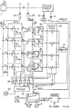
- FIG. 8 shows in a simple, analogous manner how a "one line" identification and simulation can be carried out for each container to be tested. It should be taken into account that the thermal time constants ⁇ TH differ only to a limited extent from container to container or even from container type to container type.
- two measurements are carried out here during the temperature measurement, be it with one and the same detector by successive scanning or by two staggered sensors attached along a movement path of a container 1 to be tested.
- the container 1 does not pass a first temperature sensor arrangement 31a on its path of travel after it has been subjected to the test pressure P o .
- the output signal of this measuring arrangement 31 a is applied to an identification and simulation unit 33, 35.
- the latter comprises a plurality of channels 1 to 4 etc. between inputs E, and outputs A 1 , E2 and A 2 etc.
- the output of the arrangement 31 a is at the point in time at which the container 1 is measured on the inputs E of the identification - and simulation unit 33, 35 connected.
- a switch Sa schematically represents that the output of the measuring arrangement 31 a is switched to said inputs E at time t a .
- the channels each have a function generator. As shown, the latter are extremely simple and each include, among other things, a network with high-pass characteristics, for example, RC elements, as shown. Each of the channels or the function generators assigned to them are permanently tuned to staggered time constants T ,, T2 etc.
- the container 1 Upon application of the output signal of the arrangement 31a to all channels corresponding to decreasing exponential functions with the channel-specific time constant T and the initial value corresponding to the output signal of the arrangement appear to the channel outputs A function curves 31 a at the time t a.
- the container 1 runs past a second temperature measuring arrangement 31 b , the output signal of which, as shown schematically by the switch S b , then to a number of comparators 35 1 , 35 2 , etc. is switched on, with each of the comparators 35 being connected to the output signal of one of the channels at a second input.
- Each of the comparators 35 thus compares a signal corresponding to the container temperature at the time t b with a channel output signal at the same time. If, as mentioned, the time constants of the channels T are successively staggered, for example Tl ⁇ T2 ⁇ T3 ⁇ T4 etc., the channel output signals have accordingly dropped to different extents. Thus, the comparison will indicate the comparators which channel output value the output of the temperature measuring assembly 31 b most closely corresponds. When checking all the comparator outputs, a pair of comparators will be found whose output signals are at different polarities. In the example shown, this is the case between the comparators 35 2 and 35 3 in that their output signal is indicated by * in the comparator characteristics shown.
- the interrogation of the comparator output signals takes place by means of a multiplexer unit 37. Clocked by a clock generator 39, the multiplexer unit 37 sequentially switches one comparator output after the other to a monostable unit 41. If a polarity change between two sequentially connected comparator outputs is detected, this results in the output of the multiplexer unit 37 a signal edge through which the monostable unit 41 is triggered and emits an output pulse.
- the clock pulses of the generator 39 are applied to a counter unit 43, which counts the pulses and thus identifies which of the comparator outputs is switched through by the multiplexer unit 37. If the aforementioned pulse appears at the output of the monostable unit 41, the counter 43 is (not shown) stopped.
- the channels are each assigned a count on counter 43.
- the outputs of the identification and simulation unit 33, 35, A are connected to the associated comparators 35 via changeover switches S u .
- the correction unit 9 is corrected at 8 2 predetermined limit pressure variable p G according to FIG. 1 to the relevant container temperature value t, the corrected limit pressure variable P G ( ⁇ B (t 3 ) ), as already described, together with the measured, pressure-relevant pressure variable p ( ⁇ B (t 3 )) from sensor 5, is fed to the comparison unit 13.
- the thermal behavior of the container is identified and simulated.
- the identification can also be carried out by measuring the container temperature at two times in accordance with t a and t b , and the identification can be carried out by relating the measured temperature values, such as by forming the quotient, from which the time constant results. If the time constant TTH is given, then the simulation is carried out by emulating an exponential function with an excitation corresponding to the measured values and the decay behavior corresponding to the time constant found.
- the simulated time function is queried at the point in time relevant for the density test in order to determine the container temperature during the density exercise.
- the pressure quantities are not measured directly, but indirectly by measuring physical quantities that depend on the pressure in a known manner, the corrections can also be made to the actually measured quantities, taking into account their dependence on the pressure or the temperature.
- the latter are carried out over predetermined time periods and the average temperature over these time periods is further processed as a relevant measured value.
- This can be done in known way by integrating the temperature output signals of the corresponding arrangements over a predetermined integration time, such as by an analog integrator or by relatively high-frequency sampling of the temperature output signals and subsequent digital averaging over a predetermined number of sampled signal values.
- Another problem with the temperature measurement is that it is difficult to carry out a measurement that is relevant for the temperature state of the containers, taking into account that the container temperature does not have to be the same at different container locations. This is taken into account by the fact that several temperature sensors simultaneously scan the temperature of a container and the mean value of the temperature values of all sensors is determined as the relevant container temperature value. The effort to be done for this, in particular by providing several temperature sensors, is relatively large. It must be taken into account that in most applications, the containers to be tested are not stationary with respect to a reference system with the measuring arrangements, but rather pass by at a relatively high speed on a path along which the temperature sensors are to be arranged during continuous production. A preferred arrangement of a temperature sensor, such as a pyroelectric detector, is shown in FIG.
- Containers 61 that are not yet closed run along a movement path X at the speed v.
- a pyroelectric detector 63 is fixed in the area of the container movement path X in such a way that the container openings 65 run past it. It has now been found that the thermal radiation in the interior of the container 61 is representative of the mean value of the temperature distribution along the entire container. The temperature is thus measured when a respective container 61 with its opening 65 lies in the range of the sensitivity characteristic of the pyroelectric detector 63. When this is the case can be detected by a separate position detector.
- the output signal of the detector 63 is first switched to a comparator unit 65, which is given a threshold value k o , the latter being selected such that the output signal of the detector 63 only exceeds it when an opening 65 enters its sensitivity characteristic.
- a switch S 63 is closed, for example via a monostable unit 67 or via a bistable, which is reset when the threshold value k o is fallen below again, which then switches on the output signal of the detector 63 as representative of the respective container temperature, to the devices shown in FIGS. 1 to 8 and connected downstream of the temperature measuring arrangements.
- this principle can be used, such as in the determination of relevant averaged body temperatures, as shown schematically in FIG. 10.
- a temperature relevant to its temperature state or its thermal energy content is to be measured on a body 70, with the temperature distribution in the body 70 being three-dimensionally unbalanced in the general case, an indentation 72 is worked into the body and the heat radiation S TH from that, a black one Indentation 72, which acts like a body, is measured with a detector 74, such as with a pyroelectric detector which is attached in the immediate region of the recess 72. This often eliminates the need for a very complex internal measurement of the temperature on such bodies.
Abstract
Description
Die vorliegende Erfindung betrifft ein Verfahren zur Dichteprüfung von Behältnissen, bei dem man ein Behältnis unter Druck setzt oder evakuiert und eine Druckgrösse misst, als Leckagemass-Indikation, und wobei man eine Grenzdruckgrösse für den Entscheid, ob ein Behältnis als dicht oder als undicht gewertet wird, vorgibt und man weiter, zeitlich von der Messung der Druckgrösse verschoben, eine für die dann vorherrschende Behältnistemperatur signifikante Grösse misst und eine davon abgeleitete Grösse als Korrektur der gemessenen Druckgrösse einsetzt.The present invention relates to a method for checking the density of containers, in which a container is pressurized or evacuated and a pressure quantity is measured, as a leakage measurement indication, and a limit pressure quantity for the decision as to whether a container is rated as leaky or leaky , specifies and further shifted in time from the measurement of the pressure size, a size that is significant for the then prevailing container temperature is measured and a size derived therefrom is used as a correction of the measured pressure size.
Dabei sei betont, dass eine nachfolgend als Druckgrösse" bezeichnete Grösse eine Druckdifferenz, ein Absolutdruck oder eine aus solchen abgeleitete Grösse, wie mechanische Verformung etc., sein kann.It should be emphasized here that a quantity referred to below as the "pressure quantity" can be a pressure difference, an absolute pressure or a quantity derived from such, such as mechanical deformation, etc.
Im weiteren betrifft die Erfindung eine Dichteprüfeinrichtung für Behältnisse mit einer prüfstation, worin eine für eine Behältnisleckage signifikante Druckgrösse gemessen wird, sowie mit einer Messeinrichtung für eine für die Behältnistemperatur signifikante Grösse, wobei die gemessene Druckgrösse, unter Berücksichtigung der für die Behältnistemperatur signifikanten Grösse mit einer Grenzdruckgrösse verglichen wird, für einen Entscheid, ob ein Behältnis dicht oder undicht ist.Furthermore, the invention relates to a density test device for containers with a test station, in which a pressure quantity that is significant for a container leakage is measured, and with a measuring device for a quantity that is significant for the container temperature, the measured pressure quantity, taking into account the quantity that is significant for the container temperature, with a Limit pressure size is compared for a decision whether a container is leaky or leaky.
Behältnisse werden heute mit grosser Fabrikationsgeschwindigkeit hergestellt. Dies betrifft besonders geschweisste Dosen. Die steigende Produktionsgeschwindigkeit einerseits und die Verwendung von immer dünnwandigerem Material anderseits, erfordern eine hohe Präzision beim Herstellungsprozess, damit eine hohe Dichte der Behältnisse gewährleistet ist. Auch innerhalb einer Abfüllinie, also vom Standpunkt des Dosenverarbeiters her, ist eine hohe Dichte erforderlich, damit Lebensmittel nicht verderben, umweltfeindliche, oder sehr wertvolle Materialien nicht aus den Behältnissen auslaufen. Sowohl die Hersteller, wie auch die Verarbeiter von derartigen Behältnissen sind auf eine gut funktionierende, zuverlässige Qualitätskontrolle angewiesen. Kleinste Undichten bzw. Leckagen müssen nachgewiesen werden können. Diese hohe Anforderung an die Dichteprüfung kann heute schon befriedigt werden.Containers are now manufactured at great speed. This applies particularly to welded cans. The increasing production speed on the one hand and the use of increasingly thin-walled material on the other hand require high precision in the manufacturing process so that a high density of the containers is guaranteed. A high density is also required within a filling line, i.e. from the point of view of the can processor, so that food does not spoil, environmentally unfriendly or very valuable materials do not leak out of the containers. Both the manufacturers and the processors of such containers rely on well-functioning, reliable quality control. Smallest leaks or leaks must be able to be detected. This high requirement for density testing can already be met today.
Die Prüfung der Dichte kann auf verschiedenen Wegen erfolgen. Dabei wird das Behältnis entweder durch Luft oder sonst ein Gas unter Druck oder unter Unterdruck gesetzt. Bei einem allenfalls vorhandenen Leck strömt dann Luft bzw. Gas in die bzw. von der Umgebung aus bzw. ein, wodurch sich der Behältnisinnendruck verändert.The density can be checked in different ways. The container is either pressurized or pressurized by air or another gas. If there is a leak, air or gas then flows into or out of the environment, as a result of which the internal pressure of the container changes.
Bei den einen Methoden wird der Behältnisinnendruck beobachtet, d.h. es wird die Behältnisinnendruckdifferenz innerhalb einer vorgegebenen Zeitspanne registriert und verglichen mit einer Grenzdruckänderungsgrösse, welche bei einem Behältnis auftritt, der das grösste noch tolerierbare Leck aufweist. Falls die gemessene Innendruckänderung grösser ist als die vorgegebene Grenzdruckdifferenz, dann wird das. Behältnis als Ausschuss registriert. Hier wird somit als Druckgrösse eine Aenderung des Behältnisinnendruckes beobachtet. Bei anderen Methoden wird das zu prüfende Behältnis in eine Autoklave eingeschlossen. Die Luft, welche aus dem zu prüfenden Behälter ausfliesst, strömt in die Autoklave und erhöht den dortigen Druck, was wiederum registriert wird. Hier wird somit als Druckgrösse eine Aenderung des Behältnisumgebungsdruckes registriert.In the one method, the internal pressure of the container is observed, i.e. the internal pressure difference in the container is registered within a predetermined period of time and compared with a change in the limit pressure that occurs in a container that has the largest still tolerable leak. If the measured change in internal pressure is greater than the predetermined limit pressure difference, the container is registered as a reject. A change in the internal pressure of the container is thus observed as the pressure variable. In other methods, the container to be tested is enclosed in an autoclave. The air that flows out of the container to be tested flows into the autoclave and increases the pressure there, which in turn is registered. A change in the pressure in the container environment is thus registered here as the pressure variable.
Unter Berücksichtigung, dass sich aufgrund der Leckage der Behältnisinnendruck absenkt (bei Evakuierung anhebt) und der Behältnisumgebungsdruck erhöht (bei Evakuierung erniedrigt), ist es auch durchaus möglich, in Kombination das Verhalten des Behältnisinnendruckes zum Behältnisaussendruck zu beobachten.Taking into account that due to the leakage the internal pressure of the container lowers (increases with evacuation) and the surrounding pressure increases (decreased with evacuation), it is also quite possible to observe the behavior of the internal pressure of the container to the external pressure of the container in combination.
Unter Berücksichtigung dieser verschiedenen Methoden wird im folgenden bei der Dichteprüfung generell von der Registrierung einer Druckgrösse gesprochen. Wie diese gemessen wird, direkt oder indirekt, ist-im Rahmen der vorliegenden Erfindung belanglos.Taking these various methods into account, the following generally speaks of the registration of a print size in the density test. How this is measured, directly or indirectly, is irrelevant in the context of the present invention.
Die Behälter werden entweder nach ihrer Herstellung oder nach ihrer Abfüllung auf Dichte geprüft. In beiden Fällen weisen sie dabei je nach vorangegangenem Fabrikationsablauf, undefinierte Temperaturen auf. Diese Temperatur variiert nicht nur von. Anlage zu Anlage, sondern auch innerhalb einer Anlage an derselben Stelle. Als Gründe für die Temperaturstreuung kann die Verarbeitung unterschiedlicher Behälter oder eine variable Produktionsgeschwindigkeit, eine variable Umgebungstemperatur an verschiedenen Stellen oder ein unterschiedliches Behältermaterial genannt werden. Es ist auch denkbar, dass aufgrund eines Fehlers in der Produktionsstrasse letztere angehalten werden muss, dann wieder gestartet wird, derart, dass an derselben Stelle der Produktionsstrasse, die zu prüfenden Behältnisse mit verschiedenen Temperaturen anfallen. Zum Zeitpunkt der Dichteprüfung der Behältnisse muss also die Behältnistemperatur keinesfalls immer gleich sein. Auch bei in relativ engen Toleranzen konstant gehaltener Umgebungstemperatur ist die Behältnistemperatur trotzdem nicht immer gleich, denn letztere brauchen bei der Dichteprüfstelle noch keinesfalls thermisch mit der Umgebung ausgeglichen zu sein.The containers are checked for density either after they have been manufactured or after they have been filled. In both cases, depending on the previous manufacturing process, they have undefined temperatures. This temperature does not only vary from. Plant to plant, but also within a plant in the same place. The reasons for the temperature scatter can be the processing of different containers or a variable production speed, a variable ambient temperature at different locations or a different container material. It is also conceivable that, due to a fault in the production line, the latter has to be stopped and then started again in such a way that the containers to be checked are produced at different temperatures at the same point on the production line. At the time of the density check of the containers, the container temperature does not always have to be the same. Even if the ambient temperature is kept constant within relatively narrow tolerances, the container temperature is not always the same, because the latter does not yet need to be thermally balanced with the surroundings at the density test point.
Im weiteren wird nun vom Fall gesprochen, an dem das Behältnis unter "Ueber"-Druck gesetzt wird. Die Verhältnisse bleiben aber grundsätzlich gleich, wenn das Behältnis unter "Unter"-Druck gesetzt wird. Wird nun ein Behältnis mit Luft gefüllt, so wird die Behälterwand aufgrund der erhöhten Temperatur gegenüber der eingeführten Luft Wärme an diese abgeben. Durch die dadurch bedingte Temperaturerhöhung der Luft erhöht sich bei gleichbleibendem Luftvolumen deren Druck. Die Druckdifferenz gegenüber der Umgebung wird grösser, die Luftdichte verändert sich. Somit verändert sich aber auch die Leckagerate gegenüber derjenigen, welche bei einer anderen Temperatur des gleichen Luftvolumens im Behältnis auftreten würde. Sie wird bei erhöhtem Druck grösser.In the following, we will now speak of the case in which the container is put under "over" pressure. The conditions remain basically the same, however, if the container is put under "under" pressure. If a container is now filled with air, the container wall will give off heat to the introduced air due to the increased temperature. The resulting increase in temperature of the air increases its pressure while maintaining the same air volume. The pressure difference from the environment increases, the air density changes. However, the leakage rate also changes compared to that which would occur at a different temperature of the same air volume in the container. It increases with increased pressure.
Wurde als Grenzdruckgrösse eine Druckgrösse bei einer tieferen Temperatur vorgegeben, so wird die Dose bei erhöhter Temperatur als Ausschuss gewertet, obwohl dies nicht zutrifft: Die erhöhte Leckagerate ist auf den temperaturbedingten erhöhten Innendruck zurückzuführen.If a pressure value at a lower temperature was specified as the limit pressure value, the can is rated as a waste at an increased temperature, although this is not the case: the increased leakage rate is due to the temperature-related increased internal pressure.
Aus der DE-A-3 106 981 ist es nun bekannt, an einer Druckprüfkammer für Behältnisse zwei Temperaturfühler vorzusehen, wovon der eine dem zu prüfenden Bauteil zustellbar ist. Mittels dieser Temperaturfühler wird eine Temperaturdifferenz gemessen, vor der eigentlichen Druckprüfphase und aus der gemessenen Temperaturdifferenz, welche praktisch gleichzeitig mit der Druckmessung erfolgt, wird die Druckmessung korrigiert. Nachteilig an diesem Vorgehen ist, dass an der Druckprüfstation zusätzliche Messfühler vorgesehen werden müssen, und dass die Belegungszeit der Prüfstation durch die vorzunehmende Temperaturmessung zusätzlich zur Druckmessung verlängert wird.From DE-A-3 106 981 it is now known to provide two temperature sensors on a pressure test chamber for containers, one of which can be delivered to the component to be tested. A temperature difference is measured by means of these temperature sensors, the pressure measurement is corrected before the actual pressure test phase and from the measured temperature difference, which takes place practically simultaneously with the pressure measurement. The disadvantage of this procedure is that additional measuring sensors must be provided at the pressure test station and that the occupancy time of the test station is extended by the temperature measurement to be carried out in addition to the pressure measurement.
Aus der US-A-3 987 664 ist es im weiteren bekannt, aus dem Einschwingwerhalten einer Druckgrösse zu identifizieren, ob der zu prüfende Behälter kalt, warm oder heiss ist. Hierzu werden Referenz-Kurvenverläufe abgespeichert. Der seitens eines vorzusehenden Auswertungsrechners zu betreibende Aufwand ist gross, indem empirisch und anhand von Referenzbehältnissen erfasste Referenzkurven abgespeichert und zu Vergleichszwecken beigezogen werden müssen.From US-A-3 987 664 it is further known to identify whether the container to be tested is cold, warm or hot from the settling of a pressure variable. For this purpose, reference curve profiles are saved. The effort to be provided on the part of an evaluation computer to be provided is great in that reference curves recorded empirically and using reference containers have to be stored and consulted for comparison purposes.
Im weiteren ist es aus Measurement Techniques, Band 12, No. 12, Dezember 1978, New York (US) V. T. Gladchenko et al.: "Pressure-drop system for checking the airtightness of containers", Seiten 1678 bis 1680 bekannt, wie die theoretische Abhängigkeit des Druckes in einem Behältnis von der Behältnistemperatur und der Zeit ist. Diese theoretischen Betrachtungen können grundsätzlich verwendet werden, Temperaturkompensationen im hier interessierenden Sinne vorzunehmen.Furthermore, it is from Measurement Techniques, Volume 12, No. December 12, 1978, New York (US) VT Gladchenko et al .: "Pressure-drop system for checking the airtightness of containers", pages 1678 to 1680 discloses how the theoretical dependence of the pressure in a container on the container temperature and time is. These theoretical considerations can basically be used to carry out temperature compensation in the sense of interest here.
Aus Soviet Journal Of Nondestructive Testing, Band 20, No. 6, Juni 1984, New York (US), E. l. Dogonkina et al.: "Use of microcomputers in tests of vacuum tightness". Seiten 395 bis 400 ist es im weiteren bekannt, ein zu prüfendes Behältnis unter Druck zu setzen, eine Serie von Messungen auszuführen, einschliesslich der Messung von Druck, Temperatur, Druckgradient etc. Insbesondere Druck und Temperatur werden gleichzeitig gemessen, somit in einer Druckmessstation, was wiederum das Vorsehen entsprechender Sensoren, insbesondere von Temperatursensoren, an Druckmessstationen nötig macht, mit dem entsprechenden konstruktiven, die Druckverhältnisse in der Kammer berücksichtigenden Aufwand.From Soviet Journal Of Nondestructive Testing, Volume 20, No. 6, June 1984, New York (US), E. l. Dogonkina et al .: "Use of microcomputers in tests of vacuum tightness". Pages 395 to 400 it is further known to pressurize a container to be tested, to carry out a series of measurements, including the measurement of pressure, temperature, pressure gradient, etc. In particular, pressure and temperature are measured simultaneously, thus in a pressure measuring station, what again the provision of appropriate sensors, in particular temperature sensors, at pressure measuring stations is necessary, with the corresponding constructive effort which takes the pressure conditions in the chamber into account.
Auch die JP-A-58 216 926 schlägt das gleichzeitige Messen von Druck und Temperatur vor, was bezüglich des Konstruktionsaufwandes die obgenannten Nachteile mit sich bringt.JP-A-58 216 926 also suggests the simultaneous measurement of pressure and temperature, which entails the above-mentioned disadvantages with regard to the construction effort.
Die JP-A-59 206 737 sowie die US-A-3 065 324, die DE-A-2 829 154 und die US―A―3 579 775 beschreiben spezielle Temperaturmessanordnungen bzw. Verfahren.JP-A-59 206 737 and US-A-3 065 324, DE-A-2 829 154 and US ― A ― 3 579 775 describe special temperature measuring arrangements and methods.
Aus der US―A―4 272 985 ist es nun im weiteren bekannt, um Temperaturfehler an einem Verfahren zur Dichteprüfung von Behältnissen zu korrigieren, in einem ersten Vorgehensschritt am zu prüfenden Behältnis Luft unter Umgebungsdruck einzukapseln. Druckänderungen an dieser als Anfangsbedingung unter Atmosphärendruck stehenden Luft im Behältnis sind ausschliesslich temperaturgegeben und werden registriert. In einem zweiten Vorgehensschritt wird das zu prüfende Behältnis unter Ueber- oder Unterdruck gesetzt und als Leckageindikation wird dann eine Druckgrösse gemessen. Das bei der gekapselten Umgebungsluft registrierte Druckänderungssignal wird als Korrekturgrösse für das registrierte Drucksignal verwendet. Hier wird die Druckmessung, die signifikant für die Leckage des Behältnisses ist, zeitlich verschoben von einer weiteren Druckmessung vorgenommen, die schliesslich signifikant für die Behältnistemperatur ist.From US ― A ― 4,272,985 it is now further known to correct temperature errors in a method for the density testing of containers, to encapsulate air under ambient pressure on the container to be tested in a first step. Pressure changes in this air, which is initially at atmospheric pressure in the container, are exclusively temperature-dependent and are registered. In a second step, the container to be tested is placed under positive or negative pressure and a pressure variable is then measured as a leakage indication. The pressure change signal registered in the encapsulated ambient air is used as a correction quantity for the registered pressure signal. Here the pressure measurement, which is significant for the leakage of the container, is carried out with a time offset from a further pressure measurement, which is ultimately significant for the container temperature.
Bei diesem Vorgehen ist es nachteilig, dass am selben zu prüfenden Behältnis hintereinander zwei Druckmessungen vorgenommen werden müssen, eine signifikant für die Behältnistemperatur, die zweite für die Lekkage, was relativ zeitaufwendig ist, womit die Prüfstation durch ein zu Prüfendes Behältnis lange belegt wird. Anderseits müssen an dieser Prüfstation keine zusätzlichen Sensoren vorgesehen werden, denn das temperatursignifikante Signal wird aus einer Druckmessung ermittelt, mithin mittels eines Sensors, der ohnehin vorzusehen ist.With this procedure, it is disadvantageous that two pressure measurements must be carried out in succession on the same container to be tested, one significant for the container temperature, the second for the leakage, which is relatively time-consuming, with which the test station is occupied for a long time by a container to be tested. On the other hand, no additional sensors have to be provided at this test station, since the temperature-significant signal is determined from a pressure measurement, and consequently by means of a sensor that is to be provided anyway.
Ausgehend von einem Verfahren bzw. einer Einrichtung der letztgenannten Art setzt sich die vorliegende Erfindung zum Ziel, ein Verfahren bzw. eine Dichteprüfeinrichtung obgenannter Gattung zu schaffen, bei welcher die genannten Nachteile behoben werden, d.h. die Prüfstation nur so lange belegt wird, wie dies für die Leckage signifikante Druckmessung notwendig ist und dabei gleichzeitig nicht zusätzliche Messensoren an der prüfstation vorzusehen sind.Starting from a method or a device of the latter type, the present invention aims to provide a method or a density testing device of the above-mentioned type in which the disadvantages mentioned are eliminated, i.e. the test station is only occupied as long as this is necessary for the leakage significant pressure measurement and at the same time no additional measurement sensors are to be provided at the test station.
Dies wird bei der Ausbildung des genannten Verfahrens- nach dem kennzeichnenden Teil von Anspruch 1 erreicht, bei der genannten Dichteprüfeinrichtung gemäss dem kennzeichnenden Teil von Anspruch 13.This is achieved in the formation of the said method according to the characterizing part of
Es wird somit die Temperaturmessung vor oder nach der Dichteprüfung vorgenommen. Die gemessene Temperatur kann nicht direkt zu Druckgrössenkorrekturzwecken beigezogen werden, sondern erst, nachdem durch zeitliche Vorwärts oder Rückwärts-Extrapolation auf die Temperatur im Zeitraum der Dichteprüfung geschlossen worden ist, wozu eine Vorkenntnis oder Identifikation des thermischen Verhaltens des Behältnisses erforderlich ist. Erst nach Rückschluss auf die Temperatur bei der Dichteprüfung kann letztere wiederum korrigierend auf die eine oder andere der Druckgrössen angewandt werden.The temperature measurement is thus carried out before or after the density test. The measured temperature cannot be used directly for pressure quantity correction purposes, but only after the temperature in the period of the density test has been inferred by temporal forward or backward extrapolation, which requires prior knowledge or identification of the thermal behavior of the container. Only after concluding the temperature during the density test can the latter again be applied in a corrective manner to one or the other of the pressure variables.
Es wird nun weiter vorgeschlagen, dass man das thermische Zeitverhalten des Behältnisses bestimmt, daraus gemäss Wortlaut von Anspruch 3 die Temperatur des Behältnisses im Zeitraum der Druckgrössenmessung bestimmt.It is now further proposed that the thermal time behavior of the container be determined, therefrom determines the temperature of the container in the period of the pressure measurement according to the wording of
Im weiteren wird vorgeschlagen, dass die Temperaturabhängigkeit der Grenzdruckgrösse oder der gemessenen Druckgrösse entweder nach Vorliegen der Behältnistemperatur im Zeitabschnitt der Druckgrössenmessung gemäss Wortlaut von Anspruch 4 berücksichtigt wird, oder dass diese Abhängigkeit als Funktion der unabhängigen Variablen "Temperatur" abgespeichert wird und mit der bestimmten Behältnistemperatur bei der Druckgrössenmessung in' die Funktion eingegangen wird, gemäss Wortlaut von Anspruch 5.It is further proposed that the temperature dependency of the limit pressure variable or the measured pressure variable is taken into account either after the container temperature is present in the time period of the pressure variable measurement according to the wording of claim 4, or that this dependency is stored as a function of the independent variable "temperature" and with the specific container temperature the function is included in the measurement of the pressure size, according to the wording of
Es wird weiter vorgeschlagen, gemäss Wortlaut von Anspruch 6, dass man das thermische Zeitverhalten des Behältnisses aus Messung mindestens einer Behältnistemperatur sowie Vorbestimmung der thermischen Behältniszeitkonstanten - letzteres rechnerisch, unter Berücksichtigung die Zeitkonstante festlegender Behältnis- und/oder Füllmediums-Parametern, oder aber experimentell gemäss Wortlaut von Anspruch 7 - bestimmt.It is further proposed, according to the wording of claim 6, that the thermal time behavior of the container is measured from at least one container temperature and predetermined determination of the thermal container time constant - the latter mathematically, taking into account the time constant of the container and / or filling medium parameters, or experimentally Wording of claim 7 - determined.
Diesbezüglich flexibler wird man, unter Berücksichtigung, dass sich das thermische Zeitverhalten der Behältnisse, insbesondere bei variablem Behältnistyp, ändern kann, indem man das thermische Zeitverhalten des Behältnisses aus zeitverschobenen Messungen von Behältnistemperaturen identifiziert, unter Berücksichtigung des Messungs-Zeitabstandes gemäss Wortlaut von Anspruch 8.In this regard, one becomes more flexible, taking into account that the thermal time behavior of the containers, particularly in the case of a variable container type, can be changed by identifying the thermal time behavior of the container from time-shifted measurements of container temperatures, taking into account the measurement time interval according to the wording of
Bei allen erwähnten Varianten wird die Temperaturmessung dadurch rauschunanfälliger, dass man sie durch Mittelung mehrerer Messungen über die Messzeit durchführt.In all the variants mentioned, the temperature measurement becomes less susceptible to noise by carrying out it by averaging several measurements over the measurement time.
Ein weiteres Problem bei der Temperaturmessung in allen erwähnten und noch zu erwähnenden Verfahrensvarianten ergibt sich dadurch, dass die Temperatur an Behältnis nicht ausgeglichen zu sein braucht. Zudem ist die Wärmestrahlung, die insbesondere bei kontaktloser Temperaturmessung eigentlich registriert wird, abhängig vom Material, der Oberflächenbearbeitung etc. an verschiedenen Behältnisstellen. Um deshalb eine repräsentative Temperaturmessung zu erzielen, wird weiter vorgeschlagen, dass man letztere durch Mittelung mehrerer Messungen an unterschiedlichen Behältnisstellen durchführt, gemäss Wortlaut von Anspruch 10.Another problem with temperature measurement in all the process variants mentioned and yet to be mentioned arises from the fact that the temperature of the container need not be balanced. In addition, the heat radiation, which is actually registered in particular in the case of contactless temperature measurement, depends on the material, the surface treatment, etc. at various container locations. In order to achieve a representative temperature measurement, it is further proposed that the latter be carried out by averaging several measurements at different container locations, according to the wording of claim 10.
Letzterwähntes Problem wird aber auf höchst elegante Art und Weise dadurch gelöst, dass man gemäss Wortlaut von Anspruch 11 die Behältnistemperatur vor der Druckgrössenmessung und vor Schliessen des Behältnisses durch Messung der thermischen Strahlung aus dem Behältnishohlraum durchführt, als Messung des integralen thermischen Energie-Zustandes des Behältnisses. Es hat sich nämlich gezeigt, dass der Behältnishohlraum ähnlich einem schwarzen Körper wirkt und die Temperaturstrahlung aus diesem Hohlraum bereits die gesuchte repräsentative, d.h. gemittelte Temperatur ist. Diese Messung berücksichtigt lokal unterschiedliche Innen- und Aussen-Oberflächen, -materialien etc.However, the last-mentioned problem is solved in a highly elegant manner in that, according to the wording of
Letzterwähntes Vorgehen ist insbesondere bei Relativbewegung von Behältnis und Temperaturmessanordnung ausserordentlich einfach, wobei dann in weiter vorteilhafter Weise die Aenderung der detektierten Strahlung bei Einlaufen der Behältnisöffnung in den Sensibilitätsbereich der Anordnung als Kriterium dafür verwendet wird, wann die Anordnung repräsentativ misst. Mit anderen Worten wird ausgenützt, dass die detektierte Wärmestrahlung wesentlich unterschiedlich ist, je nachdem, ob der Detektor der Anordnung die Strahlung detektiert, wenn kein Behältnishohlraum gegenüberliegt, oder wenn dies der Fali ist. Diese Aenderung wird direkt dazu ausgenützt festzulegen, wann das Detektorausgangssignal für die Behältnistemperatur repräsentativ ist, d.h. wann dieses Ausgangssignal auch weiter zu verarbeiten ist.The last-mentioned procedure is extraordinarily simple, in particular in the case of a relative movement of the container and the temperature measuring arrangement, in which case the change in the detected radiation when the container opening enters the sensitivity range of the arrangement is used as a criterion for when the arrangement measures representative. In other words, use is made of the fact that the detected thermal radiation is significantly different, depending on whether the detector of the arrangement detects the radiation if there is no container cavity opposite, or if this is the case. This change is used directly to determine when the detector output signal is representative of the container temperature, i.e. when this output signal is to be processed further.
Im weiteren wird nun an der Dichteprüfeinrichtung gemäss Wortlaut von Anspruch 14 die Messeinrichtung mit einem Eingang einer Korrektureinheit verbunden, an deren Ausgang ein Signal in Abhängigkeit des Signals an Eingang erscheint, wobei vorzugsweise der Ausgang der Korrektureinheit auf einen Eingang einer Vergleichseinheit geführt ist, mit einem zweiten Eingang, welch letzterem ein weiteres Signal zugeführt wird, das der gemessenen, für die Behältnisleckage repräsentativen Druckgrösse entspricht.Furthermore, the measuring device is now connected to an input of a correction unit at the output of the density test device, at the output of which a signal appears as a function of the signal at the input, the output of the correction unit preferably being connected to an input of a comparison unit, with a second input, to which a further signal is supplied to the latter, which corresponds to the measured pressure value representative of the container leakage.
Die Korrektureinheit umfasst in einer Ausführungsvariante eine Recheneinheit.In one embodiment variant, the correction unit comprises a computing unit.
Im weiteren wird vorgeschlagen, gemäss Wortlaut von Anspruch 16, dass ein Ausgang der Messeinrichtung auf einem Eingang einer Zeitfunktionseinheit geführt ist, dass ein Schaltorgan vorgesehen ist, welches die Vornahme der Dichteprüfung anzeigt, wobei das Schaltorgan dann das Auslesen des Ausgangssignals der Zeitfunktionseinheit ansteuert, und das Ausgangssignal der Zeitfunktionseinheit, der Behältnistemperatur bei Auslösen des Schaltorgans entsprechend, auf den Eingang der Korrektureinheit geführt ist.It is further proposed, according to the wording of claim 16, that an output of the measuring device is routed to an input of a time function unit, that a switching element is provided which indicates that the density test is being carried out, the switching element then triggering the reading of the output signal of the time function unit, and the output signal of the time function unit, corresponding to the container temperature when the switching element is triggered, is led to the input of the correction unit.
Es wird somit mit der Temperaturmessung eine Zeitfunktion gestartet, die dem thermischen Verhalten des Behältnisses entspricht und bei Vornahme der Dichteprüfung wird der dann vorherrschende Zeitfunktionswert ausgelesen.A temperature function that corresponds to the thermal behavior of the container is thus started with the temperature measurement and the prevailing time function value is read out when the density test is carried out.
Wie unter Einsatz heute üblicher Mikroprozessorentechnik wird nun weiter gemäss Wortlaut von Anspruch 17 vorgeschlagen, dass die Zeitfunktionseinheit eine Recheneinheit umfasst, mit einer Eingabeeinrichtung zur Eingabe von Behältnis- und/oder Füllmediums-parametern, und dass sie die thermische Zeitkonstante des Behältnisses berechnet und vorzugsweise, mindestens bei Auslösen des Schaltorgans aus dem Signal am Eingang der Zeitfunktionseinheit als Anfangswert der Zeitkonstanten, den Wert einer Zeitfunktion im Zeitpunkt des Auslösens berechnet und ausgibt.As is the case with the use of microprocessor technology common today, it is now further proposed according to the wording of
In einer weiteren Ausführungsvariante gemäss Anspruch 18 gibt die Messeinrichtung zu mindestens zwei Zeitpunkten einen Messwert aus und die Zeitfunktionseinheit identifiziert aus den Messwerten und der Zeitdifferenz ihres Auftretens das thermische Zeitverhalten des Behältnisses, insbesondere dessen Zeitkonstante; die Zeitfunktionseinheit simuliert dann dieses Verhalten mit mindestens einem Temperaturmesswert als Stützwert. Durch das besagte Schaltorgan wird dann ein Ausgang der Zeitfunktionseinheit auf die Korrektureinheit geschaltet, mit einem dem für die Behältnistemperatur bei der Dichteprüfung in der Prüfstation repräsentativen Signalwert.In a further embodiment variant according to claim 18, the measuring device outputs a measured value at at least two times and the time function unit identifies the thermal time behavior of the container, in particular its time constant, from the measured values and the time difference of their occurrence; the time function unit then simulates this behavior with at least one temperature measured value as a base value. The switching element then switches an output of the time function unit to the correction unit, with a signal value representative of the container temperature during the density test in the test station.
Um die Genauigkeit der Temperaturmessung zu erhöhen, wird weiter vorgeschlagen, dass die Messeinrichtung mehrere Messungen vornimmt, wie abtastet, zu unmittelbar aufeinanderfolgenden Zeitpunkten, und dass ihr eine Zeitmittelwertseinheit nachgeschaltet ist, deren Ausgangssignal als Temperaturmesswertsignal im genannten Sinne weiterverarbeitet wird, gemäss Anspruch 19.In order to increase the accuracy of the temperature measurement, it is further proposed that the measuring device take several measurements, as sampled, at immediately successive times, and that it is followed by a time average unit whose output signal is further processed as a temperature measurement value signal in the sense mentioned, according to
Um im weiteren eine in jedem Fall repräsentative Messung für den Temperaturzustand des Behältnisses zu erhalten, wird gemäss Anspruch 20 vorgeschlagen, dass die Temperaturmessanordnung mehrere Sensoren umfasst, deren Ausgänge einer Mittelwertseinheit zugeführt sind, deren Ausgangssignal wiederum weiterverarbeitet wird.In order to obtain a measurement of the temperature state of the container that is representative in any case, it is proposed according to claim 20 that the temperature measuring arrangement comprises a plurality of sensors, the outputs of which are fed to an average value unit, the output signal of which is in turn processed.
Auf höchst einfache Art und Weise wird im bereits erwähnten Sinne eine für das Behältnis repräsentative Temperaturmessung gemäss Anspruch 21, dadurch vorgenommen, dass die Messeinrichtung einen Strahlungssensor umfasst, der so relativ zum Behältnis angeordnet ist, dass dessen Oeffnung in seinem Sensibilitätsbereich liegt, und es ist, bei Relativbewegung von Behältnis und Sensor, vorzugsweise ein Positionsdetektor vorgesehen, der den Sensorausgang dann als temperaturrepräsentatives Signal weiterleitet, wenn die Behältnisöffnung im Sensibilitätsbereich des Sensors liegt. Ohne grossen Mehraufwand wird dies weiter gemäss Anspruch 22 dadurch realisiert, dass der Positionsdetektor den Sensor selbst umfasst, dem eine Schwellwerteinheit nachgeschaltet ist, welch letztere den Sensorausgang dann weiterleitet, wenn das Ausgangssignal des Sensors ihren Schwellwert erreicht.A temperature measurement representative of the container is carried out in a very simple manner in accordance with
Die Erfindung wird anschliessend beispielsweise anhand von Figuren erläutert.The invention is subsequently explained, for example, using figures.
Es zeigen:
- Fig. 1 anhand eines Blockdiagramms das erfindungsgemässe Verfahren bzw. die erfindungsgemässe Einrichtung bei quasi gleichzeitiger Temperaturmessung und Dichteprüfung,
Figur 2 in Darstellung analog zuFigur 1 eine weitere Variante des erfindungsgemässen Verfahrens bzw. der erfindungsgemässen Einrichtung,Figur 3 eine Verstärkerschaltung zur Realisation einer Korrektureinheit wie inFigur 1 eingesetzt,- Figur 4 eine Verstärkerschaltung zur Realisation einer Korrektureinheit wie in
Figur 2 eingesetzt, Figur 5 eine weitere Ausführungsvariante des erfindungsgemässen Verfahrens bzw. der erfindungsgemässen Einrichtung anhand eines Blockdiagrammes bei zeitlicher Verschiebung von Temperaturmessung und Dichteprüfung,- Figur 6 eine weitere Ausführungsvariante an der Darstellung gemäss Figur 5 bei Voridentifikation des thermischen Behältnisverhaltens und entsprechender Direktsimulation,
Figur 7 eine weitere Ausführungsvariante an der Anordnung gemäss Figur 5 für die On-line-Bestimmung des thermischen Behältnisverhaltens,Figur 8 anhand eines detaillierteren Blockdiagrammes eine weitere Ausführungsvariante der Anordnung gemäss Figur 5 zur on-line-Identifikation und Simulation des thermischen Behältnis-Zeitverhaltens,Figur 9 eine erfindungsgemässe Anordnung eines Wärmesensors, wie eines pyroelektrischen Detektors, schematisch dargestellt.
- 1 is a block diagram of the inventive method and the inventive device with quasi-simultaneous temperature measurement and density testing,
- FIG. 2 shows a further variant of the method according to the invention or of the device according to the invention in a representation analogous to FIG. 1,
- FIG. 3 shows an amplifier circuit used to implement a correction unit as in FIG. 1,
- FIG. 4 shows an amplifier circuit used to implement a correction unit as in FIG. 2,
- FIG. 5 shows a further embodiment variant of the method according to the invention or the device according to the invention using a block diagram with a time shift of the temperature measurement and density test,
- FIG. 6 shows a further embodiment variant on the representation according to FIG. 5 with pre-identification of the thermal container behavior and corresponding direct simulation,
- FIG. 7 shows a further embodiment variant of the arrangement according to FIG. 5 for the online determination of the thermal container behavior,
- FIG. 8, using a more detailed block diagram, a further embodiment variant of the arrangement according to FIG. 5 for online identification and simulation of the thermal behavior of the container,
- FIG. 9 schematically shows an arrangement according to the invention of a heat sensor, such as a pyroelectric detector.
In Figur 1 ist anhand eines Blockdiagramms eine erste Variante des vorgeschlagenen Verfahrens bzw. der entsprechenden Einrichtung dargestellt. Ein auf Dichte zu prüfendes Behältnis 1 wird mit einem Prüfdruck bezüglich seiner Umgebung Po beaufschlagt. Danach wird über eine unbestimmte Zeitspanne T das Behältnis einer Dichteprüfstation 3 bekannter Bauart zugeführt. Das Resultat der Dichteprüfung im Zeitpunkte ist eine mit einer Sensorenanordnung 5 gemessene Druckgrösse p bei der Temperatur 8, im Zeitabschnitt der Dichteprüfung, d.h. zur Zeit t,. Die Druckgrösse p, die bei der Dichteprüfung gemessen wird, ist z.B. der nach-Verstreichen der Zeitspanne T noch vorherrschende Behältnisinnendruck, beides auf den Umgebungsdruck bezogen, oder, wenn bei der Dichteprüfung das Behältnis 1 in eine Autoklave eingeführt wird, ist p, z.B. der sich dann einstellende Druck in der Autoklave. Die Technik, die angewandt wird, um die Dichteprüfung vorzunehmen, d.h., welche Druckgrösse p beobachtet wird, ist im Rahmen der vorliegenden Erfindung unwesentlich. Wesentlich ist, dass als Resultat der Dichteprüfung direkt oder indirekt eine Druckgrösse p (61) zur Verfügung steht.A first variant of the proposed method or the corresponding device is shown in FIG. 1 using a block diagram. A
Die gemessene Druckgrösse p (61) als Mass für die Leckage muss nun mit einer entsprechenden, vorgegebenen Druckgrösse PG verglichen werden, d.h. es muss festgestellt werden, ob die gemessene Druckgrösse grösser oder kleiner ist als besagte Grenz-Grösse, um zu entscheiden, ob das Behältnis als dicht oder als undicht zu bezeichnen ist.The measured pressure variable p (6 1 ) as a measure of the leakage must now be compared with a corresponding, predetermined pressure variable PG , i.e. it must be determined whether the measured pressure variable is larger or smaller than said limit value in order to decide whether the container can be described as tight or leaking.
Gemäss Figur 1 wird die Grenzdruckgrösse pG, bezogen auf eine Temperatur 82, bei welcher die Grenz- Druckgrösse PG vorgegeben wurde, abweicht. Die mit einem Temperaturmessfühler 11 gemessene Dichteprüfungstemperatur θ1 wird ebenfalls der Korrektureinheit 9 zugeführt. Letztere arbeitet grundsätzlich als Funktionsgenerator und berücksichtigt die wenigstens in erster Näherung lineare Abhängigkeit zwischen Druckgrösse p und Temperatur 8, bei konstantem Volumen. Durch Eingabe der Steigung a und Vorgabe der Grenz-Druckgrösse PG bei der Temperatur θ2 wird die Korrekturkurve, wie schematisch eingetragen, vorgegeben, mit der durch den Füher 11 erfassten Temperatur 6, in diese Funktion eingegangenen, womit die GrenzDruckgrösse PG von ihrem Temperaturbezugswert 82, bei Vorgabe, auf den tatsächlich bei der Dichteprüfung vorliegenden Temperaturwert 81, wie mit dem Sensor 11 erfasst, korrigiert wird. Am Ausgang der Korrektureinheit 9 erscheint ein dem korrigierten Grenz-Druckwert PG (θ1) entsprechendes Signal, welches nun an einer Vergleichseinheit 13 mit der gemessenen Druckgrösse nun bezogen auf die gleichen Temepraturen θ1, verglichen wird. Aus dem Vergleichsresultat am Ausgang der Vergleichseinheit 13 wird schliesslich die Selektion vorgenommen, ob das geprüfte Behältnis 1 dicht ist oder nicht.According to FIG. 1, the limit pressure variable p G , based on a
Anstelle einer Korrektur der vorgegebenen GrenzDruckgrösse PG (82), wie in Figur 1 schematisch dargestellt, ist es auch durchaus möglich, die gemessene Druckgrösse p (81), das Resultat der Dichteprüfung im Zeitpunkt t1, zu korrigieren. Hierzu wird, wie in Figur 2 schematisch dargestellt, wiederum die Temperatur θ1 im Zeitabschnitt t, der Dichteprüfung gemessen und es wird an einer Korrektureinheit 15, die wenigstens in erster Näherung lineare Abhängigkeit zwischen Druck und Temperatur bei konstantem Volumen berücksichtigend, die gemessene Druckgrösse p; gemessen bei der Temperatur θ1, auf die vorbekannte Temperatur 02 korrigiert, bei welcher die Grenzdruckgrösse pG an der Vorgabeeinheit 7 vorgegeben wurde. Die Korrektureinheiten 9 bzw, 15 lassen sich beispielsweise in analoger Bauweise höchst einfach realisieren.Instead of correcting the predetermined limit pressure variable P G (8 2 ), as shown schematically in FIG. 1, it is also entirely possible to correct the measured pressure variable p (8 1 ), the result of the density test at time t 1 . For this purpose, as shown schematically in FIG. 2, the temperature θ 1 in the time period t of the density test is again measured, and the measured pressure p is measured on a
In Figur 3 ist eine einfache Schaltung zur Realisation der Korrektureinheit 9 dargestellt. Ein der Temperatur 8, bei der Dichteprüfung entsprechendes Signal wird einem ersten Verstärker 15 zugeführt, mit Verstärkung 1, woran die Differenz dieses Signals und eines vorgegebenen, der Temperatur 62 entsprechenden Signals, gebildet wird. Letzteres entspricht der Temperatur, bei welcher die Grenz- Druckgrösse pG vorgegeben wurde. Mit dem dieser Temperaturdifferenz θ2―θ1 entsprechenden Ausgangssignal wird der Eingang eines weiteren Verstärkers 17 gespiesen, dessen Verstärkung entsprechend der Charakteristiksteigung a eingestellt wird. Durch offsetvorgabe entsprechend der Grenz- Druckgrösse PG bei Temperatur 82 wird die Verstärkerübertragungskennlinie so gelegt, dass sie bei Null-Temperaturdifferenz θ2―θ1 durch den der Grenz-Druckgrösse PG (82) entsprechenden Wert läuft, d.h. es ist dann θ1 = 82 und die vorgegebene Grenz-Druckgrösse direkt mit der gemessenen Druckgrösse vergleichbar.FIG. 3 shows a simple circuit for realizing the
In Figur 4 ist analog zu Figur 3 ein möglicher Aufbau der Korrektureinheit 15 dargestellt. An einem ersten Verstärker 19 wird ein Differenzsignal entsprechend der Differenz der Temperatur 8, bei der Dichteprüfung und der Temperatur 82, bei welcher die Grenz-Druckgrösse PG vorgegeben wird, gebildet. Hierzu weist er eine Verstärkung von 1 auf und es wird ihm ein der Temperatur 82 entsprechender Wert eingegeben. Das dieser Temperaturdifferenz (θ2―θ1) entsprechende Ausgangssignal wird einem weiteren Verstärkerkreis 21 zugeführt, dessen Verstärkung der Charakteristiksteigung a entspricht. Da es hier erforderlich ist, die Charakteristik so zu legen, dass sie durch den jeweils gemessenen Druckgrössenwert p bei der Temperatur θ1 durchläuft, wird das "Offset"-Signal des Verstärkerkreises 21 durch den Ausgang des Drucksensors 5 von Figur 2 mit einem Signal entsprechend der gemessenen Druckgrösse p (81) angesteuert. Somit erscheint am Ausgang des Verstärkerkreises 21 ein Signalwert, der in Funktion der gemessenen Dichteprüfungstemperatur 8, auf einer Geraden läuft, mit der Steigung a und der durch den jeweilig gemessenen Druckgrössenwert p (θ1) läuft, bei 82 = θ1.A possible structure of the
In Figur 5 ist ein von den anhand der Figur 1 und 2 prinzipiell dargestellten Verfahren abweichendes Verfahren dargestellt. Bei den Verfahren gemäss den Figuren 1 und 2 wird die Temperatur θ1 im Moment t, der Dichteprüfung gemessen bzw. in einem Zeitabschnitt vor oder nach der Dichteprüfung, der bezüglich der Rascheit thermischer Veränderungen am Behältnis irrelevant ist. Es ist nun in manchen Anwendungsfällen und abhängig von der für die Dichteprüfung angewandten Technik oft anzustreben, die Temperaturmessung und die Dichteprüfung zeitlich bzw. örtlich zu trennen. Wird dies vorgenommen, so ergibt die Temperaturmessung am Behältnis nicht diejenige Temperatur, die bei der Dichteprüfung des Behältnisses vorherrscht. Es muss somit unter Berücksichtigung der Zeitspanne zwischen Temperaturmessung und Dichteprüfung grundsätzlich aus der Temperaturmessung am Anfang oder am Ende dieser Zeitspanne auf die Behältnistemperatur am Ende bzw. am Anfang dieser Zeitspanne, d.h. bei der Dichteprüfung geschlossen werden.FIG. 5 shows a method that differs from the method shown in principle with reference to FIGS. 1 and 2. In the method according to FIGS. 1 and 2, the temperature θ 1 is measured at the moment t, the density test or in a time period before or after the density test, which is irrelevant with regard to the rapidity of thermal changes in the container. In some applications and depending on the technology used for the density test, the aim should often be to separate the temperature measurement and the density test from time to place. If this is done, the temperature measurement on the container does not give the temperature that prevails during the density test of the container. Taking into account the time period between the temperature measurement and the density test, the temperature of the container at the beginning or at the end of this period must be used to infer the container temperature at the end or at the beginning of this time period, ie during the density test.
Das hierzu eingeschlagene Vorgehen ist in Figur 5 dargestellt. Wiederum wird das Behältnis 1 mit einer prüfdruckgrösse Po beaufschlagt. Danach, nach einer beliebigen Zeitspanne, wird im Zeitpunkt t2 die Behältnistemperatur θB(t2) mit einer Temperaturmessvorrichtung 31 gemessen, bezogen auf die Ausgangstemperatur θa. An einer Identifikationseinheit 33 wird grundsätzlich das thermische Verhalten des Behältnisses identifiziert oder berechnet, d.h. insbesondere dessen thermische Zeitkonstante LTH. Hierzu sind an der Identifikationseinheit 33 in noch zu beschreibender Art und Weise Eingangsgrössen I einzugeben. Ist das thermische Verhalten mit der thermischen Zeitkonstanten τTH gegeben, so wird diese Grösse zusammen mit der gemessenen Behältnistemperatur θB(t2) einer Simulationseinheit 35 eingegeben. Durch Bekanntsein des Temperaturzustandes entsprechend θB im Zeitpunkt t2 und der thermischen Zeitkonstanten τTH bildet die Simulationseinheit 35 in der Zeit die elektrische Simulation des thermischen Behältnisverhaltens, d.h. die Funktion:![]()
![]()
Im dargestellten Beispiel liegt der Zeitpunkt der Temperaturmessung t2 vor dem Zeitpunkt t, der Dichteprüfung. Somit kann die Simulation durch Realisation einer exponentiell mit der thermischen Zeitkonstanten τTH abfallenden Funktion bewerkstelligt werden, die mit dem Anfangswert entsprechend θB(t2) bzw. θB)(t2)―θu angeregt wird. Der der Behältnistemperatur bei der Dichteprüfung im Zeitpunkt t, entsprechende Temperaturwert θB(t1) wird durch Abtasten bzw. Abfragen des Ausgangssignals der Simulationseinheit 35 im Dichteprüfungszeitpunkt t, ermittelt. Dies wird durch die Abtasteinheit 37 realisiert, die, ausgelöst durch einen Sensor 39, der das Stattfinden der Dichteprüfung detektiert, dann den Ausgang der Simulationseinheit 35 abfrägt. Somit erscheint am Ausgang der Abtasteinheit 37 ein Signal entsprechend: -![]()
![]()
Somit wird aus einer vorgängigen Temperaturmessung im Zeitpunkt t2 die Behältnistemperatur θB(t1) bei der nachmaligen Dichteprüfung bestimmt. Mit diesem der Temperatur entsprechenden Signal wird in Analogie zu den Ausführungen zu Figur 1 oder Figur 2, in Figur 5 in Analogie zu Figur 1 dargestellt, in die Korrektureinheit 9 eingegangen, an deren Ausgang die entsprechend der Temperaturdifferenz von Behältnistemperatur θB(t1) bei Dichteprüfung und der Temperatur (82), bei der Grenz-Druckgrössen-Vorgabe korrigierte GrenzDruckgrösse PG(θB(t1)) erscheint. Dieser Wert wird wiederum der Vergleichseinheit 13 zugeführt, zusammen mit der gemessenen, für die Dichteprüfung relevanten Druckgrösse p(θB(t1)), das Resultat des Vergleichs führt zur Selektion, ob das geprüfte Behältnis den Dichteanforderungen genügt oder nicht.The container temperature θ B (t 1 ) is thus determined from a previous temperature measurement at time t 2 during the subsequent density test. This signal, which corresponds to the temperature, is used in analogy to the explanations for FIG. 1 or FIG. 2, shown in FIG. 5 in analogy to FIG. 1, for the
Grundsätzlich ist es auch möglich, die Temperaturmessung nach der Dichteprüfung vorzunehmen und in analoger Weise die gemessene Druckgrösse oder die vorgegebene Grenz-Druckgrösse zu korrigieren, wobei dann die das thermische Behältnisverhalten simulierende Zeitfunktion rückwärts ausgewertet werden muss, was nicht mehr durch Direktsimulation in der Zeit erfolgen kann, sondern was nun rechnerisch erfolgen muss.In principle, it is also possible to carry out the temperature measurement after the density test and to correct the measured pressure or the specified limit pressure in an analogous manner, in which case the time function simulating the thermal behavior of the container must be evaluated backwards, which is no longer done by direct simulation in time can, but what must now be done arithmetically.
Für die Identifikation des thermischen Behältnisverhaltens ist es ausschlaggebend, die thermische Zeitkonstante τTH zu finden bzw. zu kennen. Dies kann auf verschiedene Art und Weise erfolgen.To identify the thermal container behavior, it is crucial to find or know the thermal time constant τ TH . This can be done in a number of ways.
Gemäss Fig. 6 wird in einer ersten Variante hierzu eine eigentliche Identifikation im Rahmen des beschriebenen Verfahrens ausgelassen. Hier wird das thermische Verhalten des Behältnisses vorab an einem Prüfbehältnis ausgemessen und daraus die thermische Zeitkonstante τTH bestimmt. Diese Grösse wird dann direkt der Simulationseinheit 35 eingegeben.6, in a first variant, an actual identification in the context of the described method is omitted. Here the thermal behavior of the container is measured in advance on a test container and the thermal time constant τ TH is determined from it. This variable is then entered directly into the
Gemäss Figur 7 kann anstelle einer experimentellen Bestimmung der thermischen Zeitkonstanten τTH des Prüflings bzw. Behältnisses 1 letztere rechnerisch bestimmt werden. Dies hat den Vorteil, dass die unter Umständen langwierige experimentelle Bestimmung der Zeitkonstanten TTH wegfällt.According to FIG. 7, instead of an experimental determination of the thermal time constant τ TH of the test piece or
Allerdings müssen hierzu die mindestens in erster Näherung die thermische Zeitkonstante TTH festlegenden Grössen bekannt sein, d.h. Wärmeübergangszahl a', spezifische Wärme cp, Dimension L des Behältnisses. Diese die Zeitkonstante bestimmenden Parameter des Behältnisses 1 und allenfalls seines Füllmediums werden in die nun als Recheneinheit ausgebildete Identifikationseinheit 33a eingegeben - Eingänge I von Figur 5 - die daraus die thermische Zeitkonstante TTH ermittelt. Diese wird, wie in Figur 5 dargestellt, wiederum der Simulationseinheit 35 zugeführt. Es versteht sich von selbst, dass falls die Identifikation auf die hier beschriebene Art und Weise rechnerisch erfolgt, auch die Simulation rechnerisch erfolgen wird, ein Vorgehen, das sich unter Einsatz bekannter Mikroprozessorentechnik, unter Berücksichtigung der Tatsache, dass mit denselben Rechenbausteinen noch weitere Steuer-, Ueberwachungsund allenfalls Regelfunktionen ausgeführt werden können, in vielen Fällen aufdrängen wird.However, to do this, the quantities defining the thermal time constant TTH , at least in a first approximation, must be known, ie heat transfer coefficient a ', specific heat cp, dimension L of the container. These parameters of the
In Figur 8 ist auf einfache analoge Art und Weise dargestellt, wie eine "One line"-Identifikation und Simulation für jeden zu prüfenden Behälter vorgenommen werden kann. Dabei ist zu berücksichtigen, dass die thermischen Zeitkonstanten τTH nur in beschränktem Bereich von Behälter zu Behälter oder gar von Behältertyp zu Behältertyp differieren.FIG. 8 shows in a simple, analogous manner how a "one line" identification and simulation can be carried out for each container to be tested. It should be taken into account that the thermal time constants τ TH differ only to a limited extent from container to container or even from container type to container type.
Grundsätzlich werden hier bei der Temperaturmessung zwei Messungen vorgenommen, sei dies mit ein und demselben Detektor durch sukzessives Abtasten oder durch zwei gestaffelt, entlang einer Bewegungsbahn eines zu prüfenden Behältnisses 1 angebrachte Sensoren. Aus Uebersichtsgründen ist in Figur 8 letzterwähnte Variante dargestellt. Das Behältnis 1 läuft auf seiner Fortbewegungsbahn, nachdem es mit Prüfdruck Po beaufschlagt worden ist, erst an einer ersten Temperatursensoranordnung 31a vorbei. Diese misst die Behältnistemperatur θB im Zeitpunkt t,. Das Ausgangssignal dieser Messanordnung 31a wird einer Identifikations- und Simulationseinheit 33, 35 aufgeschaltet. Letztere umfasst eine Mehrzahl von Kanälen 1 bis 4 etc. zwischen Eingängen E, und Ausgängen A1, E2 und A2 etc. Der Ausgang der Anordnung 31a wird im Zeitpunkt, zu welchem das Behältnis 1 ausgemessen wird, auf die Eingänge E der Identifikations- und Simulationseinheit 33, 35 aufgeschaltet. Ein Schalter Sa stellt schematisch dar, dass der Ausgang der Messanordnung 31a im Zeitpunkt ta auf besagte Eingänge E aufgeschaltet wird. Die Kanäle weisen je einen Funktionsgenerator auf. Wie dargestellt, sind letztere höchst einfach aufgebaut und umfassen unter anderem je ein Netzwerk mit Hochpass-Charakteristik, beispielsweise, wie dargestellt, RC-Glieder. Jeder der Kanäle bzw. die ihm zugeordneten Funktionsgeneratoren sind fest auf gestaffelte Zeitkonstanten T,, T2 etc. abgestimmt. Bei Anlegen des Ausgangssignals der Anordnung 31a an alle Kanäle erscheinen an den Kanalausgängen A Funktionsverläufe entsprechend abfallender Exponentialfunktionen mit den kanalspezifischen Zeitkonstanten T und dem Anfangswert entsprechend dem Ausgangssignal der Anordnung 31a zur Zeit ta. Nach einer Zeitspanne, die nicht bekannt zu sein braucht und von der Vorschubgeschwindigkeit des Behältnisses abhängig, läuft das Behältnis 1 an einer zweiten Temperaturmessanordnung 31b vorbei, deren Ausgangssignal, wie mit dem Schalter Sb schematisch dargestellt, dann auf eine Anzahl von Komparatoren 351, 352, etc. aufgeschaltet wird, wobei jedem der Komparatoren 35 an einem zweiten Eingang das Ausgangssignal eines der Kanäle aufgeschaltet ist. Somit vergleicht jeder der Komparatoren 35 ein Signal, entsprechend der Behältnistemperatur im Zeitpunkt tb mit einem Kanalausgangssignal im gleichen Zeitpunkt. Sind nun die Zeitkonstanten der Kanäle T, wie erwähnt, sukzessive gestaffelt, beispielsweise Tl<T2<T3<T4 etc., so sind die Kanalausgangssignale dementsprechend unterschiedlich stark abgefallen. Somit wird der Vergleich an den Komparatoren zeigen, welcher Kanalausgangswert dem Ausgangssignal der Temperaturmessanordnung 31b am genausten entspricht. Bei Ueberprüfung aller Komparatorausgänge wird ein Komparatorpaar gefunden werden, deren Ausgangssignale auf unterschiedlichen polaritäten liegen. Dies ist beim dargestellten Beispiel zwischen den Komparatoren 352 und 353 der Fall, indem mit * in den dargestellten Komparator-Charakteristiken deren Ausgangssignal angedeutet ist. Die Abfrage der Komparatorausgangssignale erfolgt mittels einer Multiplexereinheit 37. Getaktet durch einen Taktgenerator 39, schaltet die Multiplexereinheit 37 sequentiell einen Komparatorausgang nach dem anderen auf eine monostabile Einheit 41. Wird ein Polaritätswechsel zwischen zwei sequentiell aufgeschalteten Komparatorausgängen detektiert, so ergibt dies am Ausgang der Multiplexereinheit 37 eine Signalflanke, durch welche die monostabile Einheit 41 ausgelöst wird und einen Ausgangsimpuls abgibt.Basically, two measurements are carried out here during the temperature measurement, be it with one and the same detector by successive scanning or by two staggered sensors attached along a movement path of a
Gleichzeitig mit dem Takten der Multiplexereinheit 37 werden die Taktimpulse des Generators 39 auf eine Zählereinheit 43 gegeben, welche die Impulse zählt und somit identifziert, welcher der Komparatorausgänge jeweils durch die Multiplexereinheit 37 durchgeschaltet ist. Erscheint am Ausgang der monostabilen Einheit 41 der erwähnte Impuls, so wird (nicht dargestellt) der Zähler 43 stillgesetzt. Den Kanälen ist je ein Zählstand am Zähler 43 zugeordnet. Die Ausgänge der Identifikations- und Simulationseinheit 33, 35, A, sind über Umschalter Su mit den zugeordneten Komparatoren 35 verbunden. Diese Umschalter Su werden geöffnet, wenn der Zählstand an der Zählereinheit 43 dem kanalspezifischen Zählstand entspricht und gleichzeitig die monostabile Einheit 41 einen Impuls abgibt, was besagt, dass derjenige Kanal, bei dem dies zutrifft, dem thermischen Verhalten des Behältnisses am genauesten entspricht. Somit wird mit Erscheinen des Impulses am Ausgang der Einheit 41 über eine Decodierungseinheit 45 der entsprechende Umschalter Su des entsprechenden Kanals umgeschaltet, im dargestellten Fall somit der Umschalter Su am Kanal 3. Er schaltet das Ausgangssignal der Identifikations-und Simulationseinheit auf eine Leitung 47 um, an welcher nun ein Signal anliegt, das in der Zeit dem thermischen Verhalten des Behältnisses 1 entspricht. Erreicht nun das Behältnis 1 die Dichteprüfeinrichtung im Zeitpunkt t3, so wird dies, z.B. mit einem Positionsschalter 49 registriert, der dann einen Auslöseimpuls, wie über eine monostabile Einheit 51, abgibt. Dieser Impuls schliesst einen Schalter S(t3) und schaltet die Leitung 47 auf die bereits anhand von Figur 1 beschriebene Korrektureinheit 9 auf. Dieses dann aufgeschaltete Signal entspricht der Behältnistemperatur θB im Zeitpunkt t3, d.h. in dem für die Dichteprüfung signifikanten Zeitpunkt. Wie bereits beschrieben wurde, wird an der Korrektureinheit 9, hier nicht mehr dargestellt, bei 82 vorgegebene Grenz-Druckgrösse pG gemäss Figur 1 auf den relevanten Behältnistemperaturwert t, korrigiert, die korrigierte Grenz-Druckgrösse PG(θB(t3)) wird, wie bereits beschrieben wurde, zusammen mit der gemessenen, dichterelevanten Druckgrösse p(θB(t3)) von Sensor 5, der Vergleichseinheit 13 zugeführt.Simultaneously with the clocking of the
Somit wird bei dieser Schaltungsanordnung mit den Kanälen spezifischer Zeitkonstanten, das thermische Verhalten des Behältnisses indentifiziert und simuliert. Es versteht sich von selbst, dass die Identifikation auch durch Messung der Behältnistemperatur in zwei Zeitpunkten entsprechend ta und tb erfolgen kann und die Identifikation durch Inbeziehungsetzen der gemessenen Temperaturwerte, wie durch Quotientenbildung, erfolgen kann, aus welcher die Zeitkonstante resultiert. Ist die Zeitkonstante TTH gegeben, so erfolgt dann die Simulation durch Nachbildung einer Exponentialfunktion mit einer der Messwerte entsprechenden Anregung und der gefundenen Zeitkonstanten entsprechendem Abklingverhalten. Auch hier wird dann zu dem für die Dichteprüfung relevanten Zeitpunkt die simulierte Zeitfunktion abgefragt, um daraus die Behältnistemperatur bei der Dichteübung zu ermitteln. Es versteht sich von selbst, dass, falls die Druckgrössen nicht direkt gemessen werden, sondern indirekt durch Messung physikalischer Grössen, die in bekannter Art und Weise vom Druck abhängen, die Korrekturen auch an den tatsächlich gemessenen Grössen erfolgen können, bei Berücksichtigung ihrer Abhängigkeit vom Druck bzw. von der Temperatur.Thus, in this circuit arrangement with the channels of specific time constants, the thermal behavior of the container is identified and simulated. It goes without saying that the identification can also be carried out by measuring the container temperature at two times in accordance with t a and t b , and the identification can be carried out by relating the measured temperature values, such as by forming the quotient, from which the time constant results. If the time constant TTH is given, then the simulation is carried out by emulating an exponential function with an excitation corresponding to the measured values and the decay behavior corresponding to the time constant found. Here, too, the simulated time function is queried at the point in time relevant for the density test in order to determine the container temperature during the density exercise. It goes without saying that if the pressure quantities are not measured directly, but indirectly by measuring physical quantities that depend on the pressure in a known manner, the corrections can also be made to the actually measured quantities, taking into account their dependence on the pressure or the temperature.
Um die Genauigkeit der jeweiligen Temperaturmessungen an den Temperaturmessanordnungen 11 1 bzw. 31 zu erhöhen, werden letztere über vorgegebene Zeitabschnitte vorgenommen und der Temperaturmittelwert über diese Zeitabschnitte als relevanter Messwert weiterverarbeitet. Dies kann in bekannter Art und Weise durch Integration der Temperaturausgangssignale der entsprechenden Anordnungen über eine vorgegebene Integrationszeit erfolgen, wie durch einen analogen Integrator oder durch relativ hochfrequentes Abtasten der Temperaturausgangssignale und anschliessende digitale Mittelwertsbildung über eine vorgegebene Anzahl abgetasteter Signalwerte.In order to increase the accuracy of the respective temperature measurements on the
Im weiteren besteht ein Problem bei der Temperaturmessung darin, dass es schwierig ist, eine für den Temperaturzustand der Behältnisse relevante Messung vorzunehmen, unter Berücksichtigung, dass die Behältnistemperatur an unterschiedlichen Behältnisstellen mitnichten gleich zu sein braucht. Dies wird dadurch berücksichtigt, dass mehrere Temperaturfühler die Temperatur eines Behältnisses gleichzeitig abtasten und als relevanter Behältnistemperaturwert der Mittelwert der Temperaturwerte aller Sensoren ermittelt wird. Der hierzu zu betreibende Aufwand, insbesondere durch das Vorsehen mehrerer Temperatursensoren, ist relativ gross. Dabei muss berücksichtigt werden, dass in den meisten Anwendungsfällen die zu prüfenden Behältnisse nicht stationär sind bezüglich eines Bezugssystems mit den Messanordnungen, sondern bei Durchlaufproduktion mit relativ hoher Geschwindigkeit auf einer Bahn, entlang welcher die Temperatursensoren anzuordnen sind, vorbeilaufen. Eine bevorzugte Anordnung eines Temperaturfühlers, wie eines pyroelektrischen Detektors, ist in Figur 9 dargestellt. Entlang einer Bewegungsbahn X laufen mit der Geschwindigkeit v Behältnisse 61, die noch nicht verschlossen sind. Ein pyroelektrischer Detektor 63 ist im Bereich der Behältnisbewegungsbahn X so fixiert, dass die Behältnisöffnungen 65 an ihm vorbeilaufen. Es wurde nun gefunden, dass die thermische Strahlung im Innern des Behältnisses 61 repräsentativ ist für den Mittelwert der Temperaturverteilung entlang des ganzen Behältnisses. Somit wird die Temperatur dann gemessen, wenn ein jeweiliges Behältnis 61 mit seiner Oeffnung 65 im Bereich der Sensibilitäts-Charakteristik des pyroelektrischen Detektors 63 liegt. Wann dies der Fall ist, kann durch einen separaten Positionsdetektor detektiert werden. Wesentlich einfacher ist es jedoch auszunützen, dass, wie mit einer schematisch dargestellten Ausgangssignalfunktion U (8) des Detektors 63 dargestellt, dessen Ausgangssignal sich dann, wenn eine Lücke zwischen den Behältnissen 61 am Detektor 63 vorbeiläuft, weitgehend unabhängig von der Umgebungstemperatur vom Ausgangssignal unterscheidet, wenn der Detektor 63 einer Behältnisöffnung 65 gegenüberliegt. Somit wird das Ausgangssignal des Detektors 63 erst auf eine Komparatoreinheit 65 geschaltet, welcher ein Schwellwert ko vorgegeben wird, wobei letzterer so gewählt wird, dass das Ausgangssignal des Detektors 63 ihn nur überschreitet, wenn eine Oeffnung 65 in seine Sensibilitäts-Charakteristik einläuft. Mit dem Ausgang des Komparators 65 wird beispielsweise über eine monostabile Einheit 67 oder über eine bistabile, die bei nachmaligem Wiederunterschreiten des Schwellwertes ko rückgesetzt wird, ein Schalter S63 geschlossen, welcher das Ausgangssignal des Detektors 63 als dann repräsentativ für die jeweilige Behältnistemperatur weiterschaltet, auf die anhand Figur 1 bis 8 dargestellten, den Temperaturmessanordnungen nachgeschalteten Einrichtungen. Dieses Prinzip lässt sich abrückend vom spezifischen Einsatz zur Messung von Behältnistemperaturen in vielen anderen Technologien anwenden, wie bei der Bestimmung relevanter gemittelter Temperaturen von Körpern generell, wie schematisch in Figur 10 dargestellt. Soll an einem Körper 70 eine für seinen Temperaturzustand bzw. seinen thermischen Energieinhalt relevante Temperatur gemessen werden, wobeim allgemeinen Fall die Temperaturverteilung im Körper 70 dreidimensional unausgeglichen ist, so wird in den Körper eine Einformung 72 eingearbeitet und die Wärmestrahlung STH aus der, einen schwarzen Körper ähnlich wirkenden, Einformung 72 mit einem Detektor 74, wie mit einem pyroelektrischen Detektor, der im unmittelbaren Bereich der Einnehmung 72 angebracht wird, gemessen. Damit erübrigt sich des öftern eine sehr aufwendige Innenmessung der Temperatur an derartigen Körpern.Another problem with the temperature measurement is that it is difficult to carry out a measurement that is relevant for the temperature state of the containers, taking into account that the container temperature does not have to be the same at different container locations. This is taken into account by the fact that several temperature sensors simultaneously scan the temperature of a container and the mean value of the temperature values of all sensors is determined as the relevant container temperature value. The effort to be done for this, in particular by providing several temperature sensors, is relatively large. It must be taken into account that in most applications, the containers to be tested are not stationary with respect to a reference system with the measuring arrangements, but rather pass by at a relatively high speed on a path along which the temperature sensors are to be arranged during continuous production. A preferred arrangement of a temperature sensor, such as a pyroelectric detector, is shown in FIG.
Mit der vorgeschlagenen Temperaturberücksichtigung bei der Dichteprüfung von Behältnissen wird eine wesentliche Fehlergrösse bei bereits bekannten sehr genauen Dichteprüfungstechniken eliminiert, womit die Genauigkeit der entsprechenden Systeme erst voll ausgenützt werden kann.With the proposed temperature consideration in the density testing of containers, a significant error size in already known very precise density testing techniques is eliminated, so that the accuracy of the corresponding systems can only be fully exploited.
Claims (22)
Priority Applications (2)
| Application Number | Priority Date | Filing Date | Title |
|---|---|---|---|
| EP89110862A EP0337510B1 (en) | 1985-04-12 | 1986-04-09 | Method and apparatus for measuring heat of an open recipient and use of the method viz. apparatus for open can bodies |
| AT86901769T ATE55012T1 (en) | 1985-04-12 | 1986-04-09 | PROCEDURE FOR THE TIGHT TESTING OF CONTAINERS AND THE TIGHT TEST DEVICE THERETO. |
Applications Claiming Priority (2)
| Application Number | Priority Date | Filing Date | Title |
|---|---|---|---|
| CH157785 | 1985-04-12 | ||
| CH1577/85 | 1985-12-04 |
Related Child Applications (1)
| Application Number | Title | Priority Date | Filing Date |
|---|---|---|---|
| EP89110862.3 Division-Into | 1989-06-15 |
Publications (2)
| Publication Number | Publication Date |
|---|---|
| EP0217833A1 EP0217833A1 (en) | 1987-04-15 |
| EP0217833B1 true EP0217833B1 (en) | 1990-07-25 |
Family
ID=4213666
Family Applications (1)
| Application Number | Title | Priority Date | Filing Date |
|---|---|---|---|
| EP86901769A Expired - Lifetime EP0217833B1 (en) | 1985-04-12 | 1986-04-09 | Sealing control method for receptables and sealing control installation therefor |
Country Status (8)
| Country | Link |
|---|---|
| US (2) | US4896530A (en) |
| EP (1) | EP0217833B1 (en) |
| AT (1) | ATE118091T1 (en) |
| CA (2) | CA1288972C (en) |
| DE (2) | DE3672938D1 (en) |
| ES (2) | ES8705972A1 (en) |
| PT (1) | PT82369B (en) |
| WO (1) | WO1986006166A2 (en) |
Cited By (1)
| Publication number | Priority date | Publication date | Assignee | Title |
|---|---|---|---|---|
| DE102004039210B4 (en) * | 2004-08-12 | 2007-04-05 | Rudolf Wild Gmbh & Co. Kg | Method for evaluating product shelf life in a packaging |
Families Citing this family (21)
| Publication number | Priority date | Publication date | Assignee | Title |
|---|---|---|---|---|
| GB8707231D0 (en) * | 1987-03-26 | 1987-04-29 | Analytical Instr Ltd | Temperature compensation in pressure leak detection |
| US5065350A (en) * | 1990-03-14 | 1991-11-12 | William L. Sweet | Method and apparatus for leak testing |
| US6662634B2 (en) * | 1994-06-15 | 2003-12-16 | Martin Lehmann | Method for testing containers, use of the method, and a testing device |
| ES2088350B1 (en) * | 1993-08-12 | 1999-01-01 | Rafibra S L | PROCEDURE FOR THE TIGHTNESS CONTROL OF DEPOSITS |
| US5541520A (en) * | 1994-10-31 | 1996-07-30 | International Business Machines Corporation | Filtering for electronic module test |
| US5847264A (en) * | 1997-03-31 | 1998-12-08 | Roper Holdings, Inc. | Leak tester with flexible equation capabilities |
| DE19834332B4 (en) * | 1998-07-30 | 2005-06-02 | Robert Bosch Gmbh | Method for testing the functionality of a container |
| US6308556B1 (en) | 1999-12-17 | 2001-10-30 | Atc, Inc. | Method and apparatus of nondestructive testing a sealed product for leaks |
| US6584828B2 (en) | 1999-12-17 | 2003-07-01 | Atc, Inc. | Method and apparatus of nondestructive testing a sealed product for leaks |
| FR2803034A1 (en) * | 1999-12-28 | 2001-06-29 | Gerard Fontan | Verifying impermeability of underground liquefied gas storage cavern uses measurements of pressure, volume and temperature |
| US6408682B2 (en) | 2000-02-07 | 2002-06-25 | Steris Inc. | Leak detection method for endoscopes |
| US6412334B1 (en) * | 2000-02-07 | 2002-07-02 | Steris Inc. | Leak detector for endoscopes |
| GB0021435D0 (en) * | 2000-08-31 | 2000-10-18 | Safe Group The Ltd | A method of testing the pressure integrity of a rank |
| CN1325892C (en) * | 2001-11-27 | 2007-07-11 | 阿姆科技株式会社 | Pressure measuring method and device |
| JP2005211757A (en) * | 2004-01-28 | 2005-08-11 | National Institutes Of Natural Sciences | Separation method for hydrogen isotope and separation apparatus of hydrogen isotope |
| US20090139911A1 (en) * | 2007-11-30 | 2009-06-04 | Nova Chemicals Inc. | Method of detecting defective containers |
| DE102009040397A1 (en) * | 2009-09-07 | 2011-03-17 | Siemens Aktiengesellschaft | Diagnostic system for a valve |
| KR101512298B1 (en) * | 2013-08-07 | 2015-04-15 | 강성일 | Air tight container of easy to leak inspection and inspection method of using it and inspection apparatus |
| JP2019158755A (en) * | 2018-03-15 | 2019-09-19 | サーモス株式会社 | Liquid container and management system |
| CN109855811A (en) * | 2019-03-14 | 2019-06-07 | 中信戴卡股份有限公司 | A kind of leak hole leak rate detection device and method |
| US11567479B2 (en) | 2020-11-16 | 2023-01-31 | Stellar Idea Labs | Early warning system for food safety violation and method thereof |
Family Cites Families (23)
| Publication number | Priority date | Publication date | Assignee | Title |
|---|---|---|---|---|
| DE137277C (en) * | ||||
| US3056106A (en) * | 1958-07-14 | 1962-09-25 | Gamewell Co | Infrared detectors |
| US3065324A (en) * | 1960-09-19 | 1962-11-20 | Lindberg Eng Co | Control system for billet heaters |
| DE1573264A1 (en) * | 1965-06-14 | 1970-09-17 | Mahlo Heinz Dr Ing | Method for contactless temperature measurement of partially permeable, flat material and device for carrying out the method |
| US3708680A (en) * | 1968-06-04 | 1973-01-02 | Automatic Sprinkler Corp | Container inspection apparatus with plural detectors and rotating projection system |
| US3579775A (en) * | 1969-04-03 | 1971-05-25 | Gen Electric | Tool surface temperature measuring apparatus |
| US3742191A (en) * | 1969-07-15 | 1973-06-26 | Irtronics Inc | Infrared temperature sensor and control for use with heated, moving bodies |
| US3653263A (en) * | 1969-07-15 | 1972-04-04 | Irtronics Inc | Infrared temperature sensor and control for use with heated, moving bodies |
| US3596519A (en) * | 1970-01-21 | 1971-08-03 | Molecular Research Inc | Hot spot detector system |
| US3800586A (en) * | 1972-04-24 | 1974-04-02 | Uson Corp | Leak testing apparatus |
| US3968368A (en) * | 1975-03-10 | 1976-07-06 | Owens-Illinois, Inc. | Inspection apparatus and method for hot glass containers |
| US3987664A (en) * | 1975-12-16 | 1976-10-26 | Applied Fluidics, Inc. | Dry-testing system for detecting leaks in containers |
| DE2829154A1 (en) * | 1978-07-03 | 1980-01-17 | Bbc Brown Boveri & Cie | Temp. meter esp. for electrical machine or components - has ir conductor connected to metal sensor element which is well connected thermally |
| DE3023211A1 (en) * | 1979-06-28 | 1981-01-22 | Ti Fords Ltd | METHOD AND DEVICE FOR DETERMINING AN AQUEOUS LIQUID IN BOTTLES AND CONTAINERS |
| US4272985A (en) * | 1979-12-03 | 1981-06-16 | Uson Corporation | Method of and apparatus for compensating for temperature in leak testing |
| DE3106981C2 (en) * | 1981-02-25 | 1984-07-19 | J.W. Froehlich Maschinenfabrik GmbH, 7022 Leinfelden-Echterdingen | Device for testing components for leaks |
| DE3219409C2 (en) * | 1982-05-19 | 1984-10-11 | Schweizerische Aluminium Ag, Chippis | Method for determining the rate of oxidation at the surface of a molten metal |
| JPS59206737A (en) * | 1983-05-11 | 1984-11-22 | Cosmo Keiki:Kk | Leakage testing device having temperature compensating function |
| US4551627A (en) * | 1983-08-01 | 1985-11-05 | Kirin Beer Kabushiki Kaisha | Methods and apparatus for detecting residual liquid in containers |
| US4640627A (en) * | 1983-08-26 | 1987-02-03 | The Perkin-Elmer Corporation | Apparatus for monitoring a plasma torch |
| US4532795A (en) * | 1984-04-23 | 1985-08-06 | Semyon Brayman | Method of temperature compensating leak rate testing |
| US4625545A (en) * | 1985-04-05 | 1986-12-02 | Testrite, Inc. | Method and apparatus for detecting leaks |
| US4788427A (en) * | 1986-09-04 | 1988-11-29 | Leroy Pierre L | Fertilization detection |
-
1986
- 1986-04-09 US US07/006,554 patent/US4896530A/en not_active Expired - Fee Related
- 1986-04-09 WO PCT/CH1986/000043 patent/WO1986006166A2/en active IP Right Grant
- 1986-04-09 DE DE8686901769T patent/DE3672938D1/en not_active Expired - Lifetime
- 1986-04-09 DE DE3650224T patent/DE3650224D1/en not_active Expired - Fee Related
- 1986-04-09 AT AT89110862T patent/ATE118091T1/en not_active IP Right Cessation
- 1986-04-09 EP EP86901769A patent/EP0217833B1/en not_active Expired - Lifetime
- 1986-04-11 PT PT82369A patent/PT82369B/en not_active IP Right Cessation
- 1986-04-11 ES ES553929A patent/ES8705972A1/en not_active Expired
- 1986-04-14 CA CA000506565A patent/CA1288972C/en not_active Expired - Lifetime
-
1987
- 1987-03-02 ES ES557433A patent/ES8802630A1/en not_active Expired
-
1989
- 1989-04-21 US US07/341,485 patent/US4989990A/en not_active Expired - Fee Related
-
1990
- 1990-12-10 CA CA000615952A patent/CA1300396C/en not_active Expired - Lifetime
Cited By (2)
| Publication number | Priority date | Publication date | Assignee | Title |
|---|---|---|---|---|
| DE102004039210B4 (en) * | 2004-08-12 | 2007-04-05 | Rudolf Wild Gmbh & Co. Kg | Method for evaluating product shelf life in a packaging |
| DE102004039210C5 (en) * | 2004-08-12 | 2012-11-15 | Rudolf Wild Gmbh & Co. Kg | Method for evaluating product shelf life in a packaging |
Also Published As
| Publication number | Publication date |
|---|---|
| PT82369B (en) | 1992-07-31 |
| ES8705972A1 (en) | 1987-06-01 |
| ES557433A0 (en) | 1988-10-16 |
| ATE118091T1 (en) | 1995-02-15 |
| PT82369A (en) | 1986-05-01 |
| WO1986006166A3 (en) | 1986-11-20 |
| US4896530A (en) | 1990-01-30 |
| CA1300396C (en) | 1992-05-12 |
| WO1986006166A2 (en) | 1986-10-23 |
| DE3650224D1 (en) | 1995-03-16 |
| ES553929A0 (en) | 1987-06-01 |
| DE3672938D1 (en) | 1990-08-30 |
| CA1288972C (en) | 1991-09-17 |
| US4989990A (en) | 1991-02-05 |
| EP0217833A1 (en) | 1987-04-15 |
| ES8802630A1 (en) | 1988-10-16 |
Similar Documents
| Publication | Publication Date | Title |
|---|---|---|
| EP0217833B1 (en) | Sealing control method for receptables and sealing control installation therefor | |
| EP0619015B1 (en) | Method of testing a container, test device, use | |
| DE69133306T2 (en) | Testing hollowware in a production line with a pressure difference when a certain pressure is reached | |
| EP3198251B1 (en) | Device and method for calibrating a film chamber for leak detection | |
| DE19546182A1 (en) | Method and device for improved flow and pressure measurement and control | |
| DE102006043499A1 (en) | Method and device for diagnosing fluid losses in pressure transducers filled with pressure-transmitting fluids | |
| EP0786654A2 (en) | Installation for leak testing of containers | |
| EP3394588B1 (en) | Gross leak measurement in an incompressible test item in a film chamber | |
| DE10018493C1 (en) | Dynamic calibration device for piezoelectric pressure sensor uses signal from reference pressure sensor for regulating pressure in fluid-filled pressure chamber used for calibration | |
| DE19513199A1 (en) | Method and device for leak testing of housings | |
| DE112004002001T5 (en) | Calibration and validation for a leak detector | |
| DE102017204102A1 (en) | Method for testing a container for leaks | |
| DE2919230A1 (en) | MEASURING METHOD AND CIRCUIT FOR CONTINUOUS HUMIDITY MEASUREMENT | |
| DE10025578C2 (en) | Test and calibration device for an evaluation circuit of a linear oxygen probe (lambda probe) | |
| DD206176A3 (en) | METHOD AND CIRCUIT ARRANGEMENT FOR TEMPERATURE MEASUREMENT | |
| DE2835162A1 (en) | PROCEDURE FOR CHECKING GAS PRESSURE IN A NUCLEAR FUEL | |
| DE3219499A1 (en) | Method for the pneumatic measurement of the volume of a cavity or of the volumes of a plurality of cavities in a workpiece, in particular the combustion chamber volumes of a cylinder head | |
| DE4412762C2 (en) | Method and device for testing the water resistance of watch cases | |
| DE3106981C2 (en) | Device for testing components for leaks | |
| DE4315336A1 (en) | Method and device for measuring and correcting process variables | |
| DE10258017A1 (en) | Leakage measurement arrangement comprises a test volume connected to a test item so that any pressure change between the test volume and a reference volume can be related to a leak in the test item | |
| EP0620427A2 (en) | Procedure for the continuous inspection of plastic bottles | |
| EP2177889A1 (en) | Method and device for testing leak tightness | |
| DE102004036133B4 (en) | Test gas volume determining method for e.g. container, involves determining pressure-measured values of two volumes, total pressure-measured value of two volumes, determining one volume value based on measured valves | |
| EP0337510B1 (en) | Method and apparatus for measuring heat of an open recipient and use of the method viz. apparatus for open can bodies |
Legal Events
| Date | Code | Title | Description |
|---|---|---|---|
| PUAI | Public reference made under article 153(3) epc to a published international application that has entered the european phase |
Free format text: ORIGINAL CODE: 0009012 |
|
| 17P | Request for examination filed |
Effective date: 19861121 |
|
| AK | Designated contracting states |
Kind code of ref document: A1 Designated state(s): AT BE CH DE FR GB IT LI LU NL SE |
|
| 17Q | First examination report despatched |
Effective date: 19880329 |
|
| ITF | It: translation for a ep patent filed |
Owner name: STUDIO INGG. FISCHETTI & WEBER |
|
| GRAA | (expected) grant |
Free format text: ORIGINAL CODE: 0009210 |
|
| AK | Designated contracting states |
Kind code of ref document: B1 Designated state(s): AT BE CH DE FR GB IT LI LU NL SE |
|
| REF | Corresponds to: |
Ref document number: 55012 Country of ref document: AT Date of ref document: 19900815 Kind code of ref document: T |
|
| XX | Miscellaneous (additional remarks) |
Free format text: TEILANMELDUNG 89110862.3 EINGEREICHT AM 09/04/86. |
|
| GBT | Gb: translation of ep patent filed (gb section 77(6)(a)/1977) | ||
| REF | Corresponds to: |
Ref document number: 3672938 Country of ref document: DE Date of ref document: 19900830 |
|
| ET | Fr: translation filed | ||
| PLBE | No opposition filed within time limit |
Free format text: ORIGINAL CODE: 0009261 |
|
| STAA | Information on the status of an ep patent application or granted ep patent |
Free format text: STATUS: NO OPPOSITION FILED WITHIN TIME LIMIT |
|
| 26N | No opposition filed | ||
| ITTA | It: last paid annual fee | ||
| PGFP | Annual fee paid to national office [announced via postgrant information from national office to epo] |
Ref country code: SE Payment date: 19940308 Year of fee payment: 9 |
|
| PGFP | Annual fee paid to national office [announced via postgrant information from national office to epo] |
Ref country code: BE Payment date: 19940309 Year of fee payment: 9 |
|
| PGFP | Annual fee paid to national office [announced via postgrant information from national office to epo] |
Ref country code: DE Payment date: 19940317 Year of fee payment: 9 |
|
| PGFP | Annual fee paid to national office [announced via postgrant information from national office to epo] |
Ref country code: GB Payment date: 19940330 Year of fee payment: 9 |
|
| PGFP | Annual fee paid to national office [announced via postgrant information from national office to epo] |
Ref country code: LU Payment date: 19940331 Year of fee payment: 9 |
|
| PGFP | Annual fee paid to national office [announced via postgrant information from national office to epo] |
Ref country code: AT Payment date: 19940426 Year of fee payment: 9 |
|
| PGFP | Annual fee paid to national office [announced via postgrant information from national office to epo] |
Ref country code: FR Payment date: 19940427 Year of fee payment: 9 |
|
| PGFP | Annual fee paid to national office [announced via postgrant information from national office to epo] |
Ref country code: NL Payment date: 19940430 Year of fee payment: 9 |
|
| EPTA | Lu: last paid annual fee | ||
| PGFP | Annual fee paid to national office [announced via postgrant information from national office to epo] |
Ref country code: CH Payment date: 19940624 Year of fee payment: 9 |
|
| EAL | Se: european patent in force in sweden |
Ref document number: 86901769.9 |
|
| PG25 | Lapsed in a contracting state [announced via postgrant information from national office to epo] |
Ref country code: LU Free format text: LAPSE BECAUSE OF NON-PAYMENT OF DUE FEES Effective date: 19950409 Ref country code: GB Effective date: 19950409 Ref country code: AT Effective date: 19950409 |
|
| PG25 | Lapsed in a contracting state [announced via postgrant information from national office to epo] |
Ref country code: SE Effective date: 19950410 |
|
| PG25 | Lapsed in a contracting state [announced via postgrant information from national office to epo] |
Ref country code: LI Effective date: 19950430 Ref country code: CH Effective date: 19950430 Ref country code: BE Effective date: 19950430 |
|
| BERE | Be: lapsed |
Owner name: LEHMANN MARTIN Effective date: 19950430 |
|
| PG25 | Lapsed in a contracting state [announced via postgrant information from national office to epo] |
Ref country code: NL Effective date: 19951101 |
|
| GBPC | Gb: european patent ceased through non-payment of renewal fee |
Effective date: 19950409 |
|
| REG | Reference to a national code |
Ref country code: CH Ref legal event code: PL |
|
| PG25 | Lapsed in a contracting state [announced via postgrant information from national office to epo] |
Ref country code: FR Effective date: 19951229 |
|
| NLV4 | Nl: lapsed or anulled due to non-payment of the annual fee |
Effective date: 19951101 |
|
| PG25 | Lapsed in a contracting state [announced via postgrant information from national office to epo] |
Ref country code: DE Effective date: 19960103 |
|
| EUG | Se: european patent has lapsed |
Ref document number: 86901769.9 |
|
| REG | Reference to a national code |
Ref country code: FR Ref legal event code: ST |
|
| PG25 | Lapsed in a contracting state [announced via postgrant information from national office to epo] |
Ref country code: IT Free format text: LAPSE BECAUSE OF NON-PAYMENT OF DUE FEES;WARNING: LAPSES OF ITALIAN PATENTS WITH EFFECTIVE DATE BEFORE 2007 MAY HAVE OCCURRED AT ANY TIME BEFORE 2007. THE CORRECT EFFECTIVE DATE MAY BE DIFFERENT FROM THE ONE RECORDED. Effective date: 20050409 |