EP0217571B2 - Data transfer communication system - Google Patents
Data transfer communication system Download PDFInfo
- Publication number
- EP0217571B2 EP0217571B2 EP86306980A EP86306980A EP0217571B2 EP 0217571 B2 EP0217571 B2 EP 0217571B2 EP 86306980 A EP86306980 A EP 86306980A EP 86306980 A EP86306980 A EP 86306980A EP 0217571 B2 EP0217571 B2 EP 0217571B2
- Authority
- EP
- European Patent Office
- Prior art keywords
- bit
- data bus
- signal
- message
- data
- Prior art date
- Legal status (The legal status is an assumption and is not a legal conclusion. Google has not performed a legal analysis and makes no representation as to the accuracy of the status listed.)
- Expired - Lifetime
Links
- 238000004891 communication Methods 0.000 title claims description 27
- 238000012546 transfer Methods 0.000 title claims description 14
- 230000006870 function Effects 0.000 claims description 83
- 230000005540 biological transmission Effects 0.000 claims description 48
- 238000000034 method Methods 0.000 claims description 21
- 238000012544 monitoring process Methods 0.000 claims description 3
- 230000002401 inhibitory effect Effects 0.000 claims description 2
- 238000010586 diagram Methods 0.000 description 13
- 241001417501 Lobotidae Species 0.000 description 5
- 230000000694 effects Effects 0.000 description 4
- 230000006872 improvement Effects 0.000 description 3
- 230000001360 synchronised effect Effects 0.000 description 3
- 230000004913 activation Effects 0.000 description 2
- 238000001994 activation Methods 0.000 description 2
- 238000001514 detection method Methods 0.000 description 2
- 238000009434 installation Methods 0.000 description 2
- 230000015654 memory Effects 0.000 description 2
- 230000008569 process Effects 0.000 description 2
- 101100172132 Mus musculus Eif3a gene Proteins 0.000 description 1
- 230000004308 accommodation Effects 0.000 description 1
- 238000007792 addition Methods 0.000 description 1
- 239000012080 ambient air Substances 0.000 description 1
- 230000008901 benefit Effects 0.000 description 1
- 239000000969 carrier Substances 0.000 description 1
- 230000008859 change Effects 0.000 description 1
- 230000001186 cumulative effect Effects 0.000 description 1
- 230000003247 decreasing effect Effects 0.000 description 1
- 230000001934 delay Effects 0.000 description 1
- 238000012217 deletion Methods 0.000 description 1
- 230000037430 deletion Effects 0.000 description 1
- 230000001419 dependent effect Effects 0.000 description 1
- 239000000835 fiber Substances 0.000 description 1
- 239000000446 fuel Substances 0.000 description 1
- 239000002828 fuel tank Substances 0.000 description 1
- 230000000977 initiatory effect Effects 0.000 description 1
- 238000012986 modification Methods 0.000 description 1
- 230000004048 modification Effects 0.000 description 1
- 230000001105 regulatory effect Effects 0.000 description 1
- 230000008672 reprogramming Effects 0.000 description 1
- 230000004044 response Effects 0.000 description 1
- 230000008054 signal transmission Effects 0.000 description 1
- XLYOFNOQVPJJNP-UHFFFAOYSA-N water Substances O XLYOFNOQVPJJNP-UHFFFAOYSA-N 0.000 description 1
Images


Classifications
-
- H—ELECTRICITY
- H04—ELECTRIC COMMUNICATION TECHNIQUE
- H04L—TRANSMISSION OF DIGITAL INFORMATION, e.g. TELEGRAPHIC COMMUNICATION
- H04L12/00—Data switching networks
- H04L12/28—Data switching networks characterised by path configuration, e.g. LAN [Local Area Networks] or WAN [Wide Area Networks]
- H04L12/40—Bus networks
- H04L12/40143—Bus networks involving priority mechanisms
- H04L12/40163—Bus networks involving priority mechanisms by assigning priority to messages according to a message field
-
- H—ELECTRICITY
- H04—ELECTRIC COMMUNICATION TECHNIQUE
- H04L—TRANSMISSION OF DIGITAL INFORMATION, e.g. TELEGRAPHIC COMMUNICATION
- H04L12/00—Data switching networks
- H04L12/28—Data switching networks characterised by path configuration, e.g. LAN [Local Area Networks] or WAN [Wide Area Networks]
- H04L12/40—Bus networks
- H04L12/407—Bus networks with decentralised control
- H04L12/413—Bus networks with decentralised control with random access, e.g. carrier-sense multiple-access with collision detection [CSMA-CD]
- H04L12/4135—Bus networks with decentralised control with random access, e.g. carrier-sense multiple-access with collision detection [CSMA-CD] using bit-wise arbitration
-
- H—ELECTRICITY
- H04—ELECTRIC COMMUNICATION TECHNIQUE
- H04L—TRANSMISSION OF DIGITAL INFORMATION, e.g. TELEGRAPHIC COMMUNICATION
- H04L12/00—Data switching networks
- H04L12/28—Data switching networks characterised by path configuration, e.g. LAN [Local Area Networks] or WAN [Wide Area Networks]
- H04L12/40—Bus networks
- H04L2012/40267—Bus for use in transportation systems
- H04L2012/40273—Bus for use in transportation systems the transportation system being a vehicle
-
- H—ELECTRICITY
- H04—ELECTRIC COMMUNICATION TECHNIQUE
- H04L—TRANSMISSION OF DIGITAL INFORMATION, e.g. TELEGRAPHIC COMMUNICATION
- H04L7/00—Arrangements for synchronising receiver with transmitter
- H04L7/04—Speed or phase control by synchronisation signals
- H04L7/06—Speed or phase control by synchronisation signals the synchronisation signals differing from the information signals in amplitude, polarity or frequency or length
Definitions
- the present invention relates to the field of electrical communication networks and more specifically to the area of such networks ideally suited forthe control of electrical functions in the vehicular environment.
- TDM Time Division Multiplexing
- a master timing node is used as a controller to provide a synchronized set of dedicated time slots for which each slave node is obliged to synchronize with and obtain its communication data therefrom.
- the dedicated time slots in the TDM each provide control information of a prescribed type and those slave nodes which are programmed to perform the prescribed function must be synchronized in such a way so as to extract information from the time slot correspondingly dedicated to that function.
- Each "receiver" slave node must know exactly when its control function occurs in the data stream.
- TDM systems In addition to the TDM's dependence on the master node operation, TDM systems generally have poor flexibility due to the limited allocation of time slots in the data stream. Accordingly, additions or deletions of types of receivers in a particular network require a reallocation of the time slots through programming of the master control node.
- TDM systems also operate on an open loop system in which there is generally no positive acknowledgment that a particular control function has been received. Consequently, TDM systems usually provide a continuous update of control data as long as a particular function is being instructed.
- Some master/slave network architectures use a polling technique. This is considered an improvement over traditional TDM systems since the master can dynamically reassign time slots. However, all network transactions are dependent on a master node and redundant master nodes are required if the system is to be reliable.
- a significant improvement over Time Division Multiplex networks is provided by a Bus Contention (BC) network architecture.
- a Bus Contention network is characterized by a unified system of nodes, each capable of accessing the network based on its own requirements. There are no "master” nodes, nor any dependence on any particular nodes for network operation.
- BC nodes Instead of the dedicated time slots used in TDM, BC nodes have an "address" by which they are identified. This address uniquely identifies a node to all other parts of the network system. Control messages are directed by the address to the specific node that is responsible for a particular control function.
- the BC system has far greater efficiency than TDM systems because network activity is directly related to requests for activation.
- the bus in not burdened with the constant repetition of control signals which are not active. Messages flow between the nodes, as needed, without the intervention of a master controller. Such a method allows for greater adaptability and expandability of the network. New nodes are simply connected to the bus. No reallocation of time slots is required and existing nodes are not affected.
- a requirement for the BC type of network architecture is for media access resolution. Because all nodes are capable of network access (i.e., "transmitting") based on their individual needs, a method of resolving conflicts arising from simultaneous transmitter activations is required.
- CSMA/CD Carrier Sense Multiple Access with Collision Detection
- Token Passing schemes are most common. These, however, are optimized for physically (and electrically) large networks where message propagation delay between nodes is large. Collisions often are not detected until both transmitters are well into their individual message sequences.
- An "abort and retry" scheme is used to resolve the conflict, whereby, both messages are aborted and both transmitters must make attempts to retransmit at a later time.
- the D 2 B method relies on small network propagation delays, being much less than a single bit period. For a given size network, this places an upper bound on the potential frequency response or bit rate of the network. Because the network "looks" small electrically, each bit of a message exists at all points on the network simultaneously. Each transmitter, therefore, is aware of network activity on a bit-by-bit basis in real time. This allows a technique of message arbitration which resolves conflicts "on the fly". Messages are not destroyed in the arbitration process; rather, the network "sees" one of the conflicting messages as being valid. The losing transmitter detects this and tries again as soon as the first message has passed.
- BC network architecture where each node has a unique address, is characterized by messages which have specific transmit origins and receive destinations. These "node-to-node" messages contain specific references to the physical address of both the transmitter and receiver, along with a data field which contains an encoded description of a particular activity to take place. While BC network configurations are a significant improvement over TDM systems, there are still aspects of network operations unique to automotive requirements which are not completely addressed by the node-to-node schemes.
- US-A-4 516 205 discloses a control system for data transmission network of bus configuration which permits each communication unit in turn access to the network when that communication unit finds the network available.
- Each data station is assigned a unique address and after each data transmission on the network, those communication units having data for transmission compare their data station addresses bit by bit to determine the communication unit having highest priority. The priority can be determined from the data station addresses themself or as a result of an algorithm which might include the address of the data stations and the address of that data station which has just completed transmission.
- An article entitled "Enhanced message addressing capabilities for computer network" (Proceeding of the IEEE, Volume 66, No. 11 November 1978 PP1517-27; J. McQuillan) discloses a computer network wherein three message addressing modes are used; 1) Logical addressing, in which a permanently assigned address denotes one or more physical addresses. This permits multiple connections from the subscriber to the network as well as other functions; 2) broadcasting addressing, in which a message is addressed to all subscribers; 3) Group addressing and multidestination addressing, in which a message carries the name of a list of addresses or the list itself.
- WO-A-8 403 020 discloses an apparatus for interfacing digital devices with a communication bus in a local-area computer network.
- Each device in a network is connected to the bus through a bus interface unit providing the device user with the abilitytoestab- lish a connection with another device by means of a simple CALL command that does not require the use of physical identifiers.
- the unit also allows the user to enter a TALK mode in which a two way conversation may be conducted over the network.
- a remode command allows an unattended device to be controlled from another user site and also permits one user to connect two remotely located devices.
- a message command allows a message to be stored and held for a remote user without the intervention of a host computer.
- a data transfer communication system comprising a common data bus (20), a plurality of communication control modules (30,32,34,38) each connected to said data bus (20) each control module having a unique identifying address and being programmed to perform one or more predetermined functions, and each module containing means (32b, 38b) for receiving and means (32d, 38d) for transmitting data messages from or to other control modules on said common data bus, characterised in that each of said control module includes means (32n,38n) for providing binary bit signals on said data bus having a bit length of a predetermined bit-time period with each bit-time period subdivided into at least three predetermined subbit-time periods, a first of said binary bit signals being represented by placing said data bus in its dominant state during the first subbit-time period followed by placing said data bus in its passive state for the remaining two subbit-time period of said bit-time period and a second of said binary bit signals being represented by placing said data bus in its dominant state for the first two subbit-time periods
- the protocol employed by the present invention allows each node to be treated as equal participants on the network since there are no specific transmitters, receivers, or timing masters.
- all nodes are capable of receiving and initiating commands, and informational data transfers on either a node-to-node basis or a global network transmission basis.
- the present invention utilizes a distributed control environment whereby any control module programmed as having the ability to make global (broadcast) transmission of functional commands across the network may do so and other control modules that are programmed to receive such functional commands receive, acknowledge and act on the transmitted functional commands.
- each function or data message includes an independent priority field wherein each type of message that is allowed to be transmitted is identified according to as predetermined priority hierarchy for bus access.
- the priority field guarantees network access in less than one massage period for high priority messages.
- High priority functions on an automotive vehicle may be, for example, a functional command from the control module monitoring brake pedal to the control modules which are preprogrammed to respond to "brake light on" functional commands and turn on the brake lights.
- lesser but also high priority function commands would involve the switching on of headlamps, the dimming of high beam headlamps, the actuation of door locks and the actuation of a horn.
- each message period includes a positive acknowledgment portion through which each receiving control module will provide its unique address on the data bus.
- a systemwide handshaking technique gives positive indication to the transmitting module that the message was received and the identity of each receiver.
- Each message sent on the system is also protected by a message-wide checksum for error detection.
- the checksum is transmitted as part of the message and receiver acknowledgments are only made after the checksums accumulated by the receiver and in the received message are compared and found to correspond.
- the receiver acknowledgments are protected by a parity bit to force the receiver address to a predetermined odd or even sum.
- the present invention is viewed as being ideally suited for installation in an automotive vehicle, such as that shown in Figure 1.
- an engine 12 is shown in order to give perspective to the overall layout of the vehicle with h respect to t he present invention.
- the data communication system is shown as utilizing a single data bus communication link 20 that is routed to various control modules around the vehicle. In this instance, a twisted wire medium is used as the data bus 20.
- other transmission mediums such as fiber optics, acoustical carriers or coaxial cables may be substituted.
- a control module 30 is illustrated as being located at the forward right corner of the vehicle.
- the control module 30 is intended to receive functional commands and control the operation of head- lamps, parking lamps, highbeams, turn signals, warning flasher lamps and a horn located in that general area of the vehicle.
- a control module 32 in the forward left portion of the vehicle functions in a manner similar to control module 30 to provide control of the various lamps at that location.
- Control module 34 resides on or close to the engine 12 so as to provide information from such engine mounted sensors as oil level, water temperature and engine speed to the data bus for transmission to other control modules connected thereto
- Control module 36 is located in the area of the instrument panel of the vehicle 10 in order to control instrument lighting and provide appropriate information to instruments thereon regarding the various sensed operational parameters within the vehicle.
- Control module 38 is shown connected to the steering column of the vehicle 10 and is intended to have inputs from various associated switches to control many of the functions which take place in the vehicle. For instance, headlights, parking lights, turn signals and horn actuation would most likely be controlled by switches connected to the control module 38.
- a brake pedal sensor switch may be connected to either control module 36 or 38 depending upon the vehicle configuration.
- Control modules 40, 42, 50 and 52 are shown as located in the doors of the vehicle 10 to provide interconnection to the various window raising and lowering motors, the door lock actuators, door open/close sensor switches, convenience lighting and in the case of the control modules 40 and 52 on the front doors, power seat control switches.
- the control module 54 is shown as being located central to the vehicle, preferably under the front seats of the vehicle in order to supply control information to the seat adjustment motors and seat-belt connection sensors.
- Control modules 46 and 48 are shown as located in opposite corners at the rear of vehicle 10 in order to control the functional operation of the various lamps located at the rear of the vehicle including stop lights, back up lights, running lights, turn signals, emergency flashers and to provide fuel level sensor information to the data bus.
- FIG 2 is an example of a relationship of two control modules 32 and 38 connected to the data bus 20.
- each control module is connected to a power bus 22.
- the power bus 22 is not shown in Figure 1, it is understood that the power bits 22 would run throughout the vehicle to supply the necessary electrical power to the various accessories that are controlled by the control modules.
- each wire of the data bus 20 is biased to separate passive levels.
- a first wire is biased through a resister R1 to a regulated voltage supply of approximately 5 volts.
- the other wire of the data bus 20 is biased through a resister R2 to ground. Therefore, in the passive state, one wire is at approximately 5 volts DC and the other wire at ground potential. Accordingly, when a logic bit signal is placed on the data bus, and the data bus is energized to its dominate state for period of time, the normally 5 volt biased line will be driven to approximately ground potential and the normally zero biased line will be driven to approximately a 5 volt level.
- This technique allows for increased reliability of signal transmission and reception via differential drivers and receivers.
- each control module contains an interface circuit 321 (381) which includes a differential driver 320 (38D) and a differential receiver 32B (38B).
- Each control module includes a control processor 32C (38C) and node processor.
- the present embodiment of the invention utilizes Intel 8751 microcomputers for respective control and node processors.
- the control processor controls the network communication tasks while the node processor controls the local tasks orfunctions.
- the control microprocessors on the network all utilize identical programming to accomplish the network control task, each contains a unique address to identify that particular control module and unique function codes stored in its memory that correspond to the particular functions handled by its associated node processor.
- the control processor besides communicating with the network through the interface circuit, also communicates through a parallel interface with the node processor.
- the node processor interfaces with various devices in an area of its physical location through its various I/O ports to provide appropriate inter-connection to the power bus 22. Resident software in each node processor gives the particular processor a specific "personality" since each node processor controls or responds to different elements in the vehicle.
- control processor appears to the node processor as a series of read/write registers which contain various status and data information.
- the node processor initializes and performs network transmissions by writing information to those registers and receives messages by reading other registers. All register read/write operations take place over a parallel data bus interconnecting the two processors.
- the process for reading and writing those registers is coordinated by the four control lines designated as "data/pointer”, “read/write”, "strobe” and "busy”. All but the busy line are inputs to the control processor.
- the busy line is used to indicate that the control processor is occupied performing some task relative to the node processor interface.
- control processor receives through the parallel interface to the node processor, information, in byte form, to be formed into the protocol for transmission on the data bus 20.
- control processor is also responsible for recognition and decoding of formatted messages from the bus.
- the basic unit of communication in the network protocol of the present invention is the message format.
- Each message is intended to be from 40 to 121 bits long, depending on the message type.
- the message period requires from 8 milliseconds to 24.2 milliseconds, depending upon the message length.
- Typical message periods are approximately 10 milliseconds long, resulting in a 100 message per second network capacity.
- utilizing a higher bit clock rate would increase the message capacity of the network.
- the present invention uses two general types of messages.
- a node-to-node type message is designated with a specific transmitter and receiver address contained in the message.
- a second general type of message is a functional message which is intended for global broadcast distribution on the network.
- a first type of functional message is termed herein as a "functional command” message, where the entire message is transmitted and acknowledged as received by one or more othercontrol modules programmed to receive the particular function command contained in the message.
- Asecond type offunctional message is termed herein as a "functional data transfer" message which is an expansion of the functional command message to include informational data following the receiver acknowledgment portion for global distribution on the network.
- FIG. 3 illustrates the basic message format as employed in the present invention.
- the basic format contains a message descriptor segment and a receiver acknowledgment segment.
- a data segment may also be provided in certain types of messages (node-to-node and functional data transfer).
- a unique start bit is first provied followed by a priority code.
- the priority code is utilized for message arbitration on a bitwise basis and will be discussed below with respect to Figure 11.
- Following the priority code is a type control code that indicates which of the two general types of messages is being transmitted.
- the following field contains either function address as is employed in the broadcast functional messages or a specific receiver address in the event the message is a type intended for node-to-node communication.
- the following field contains the transmitter address followed by a message checksum field.
- the receiver acknowledgment segment of t he basic message format shown in Figure 3 is either variable in length, when the message type is a broadcast functional type message so as to accommodate any number of receivers attempting to acknowledge receipt of the message, or of a fixed length, if the transmitted message is a node-to-node type message to accommodate the acknowledgment by one particular receiver of its unique address.
- the data segment follows the receiver acknowledgment segment in the event the message is a node-to-node type or a functional information type and includes a string of data up to a predetermined limit.
- the present invention has the advantage of providing global network messages that can replace several node-to-node messages.
- node-to-node messages need to carry sensor information such as engine speed, vehicle speed or temperature to a specific control module, such messages are also accommodated.
- sensor information such as engine speed, vehicle speed or temperature
- a specific control module such messages are also accommodated.
- a message for turning on or off emergency flashers on a vehicle it is seen as most efficient to provide a functional command that is broadcast to all of the control modules. Only those control modules connected to the lamps which serve as emergency flashers will, of course, respond to the functional command message on a single transmission of the message.
- Such an accommodation eliminates the necessity to broadcast four separate node-to-node messages to control the four separately located and controlled flasher lamps.
- acknowledgment In order to provide a secure system, acknowledgment must be accommodated. Since there is an unspecified number of receivers that will receive and respond to a particular functional type message, the present system provides for a variable period in the receiver acknowledgment segment of each message.
- the function command message format is shown in Figure 4 as including the unique start signal occupying a two bit field.
- Athree bit field for the priority signal follows the start signal and a two bit field for the control signal follows the priority signal.
- the control signal will indicate a function command type message being transmitted.
- the following eleven bit field contains a generic function address in the first seven bits and a specific function address in the remaining four bits.
- a generic function might appear as "head-lamps" while the specific function may appear as "on” or "off'.
- Another generic function command may appear as "door locks” while the associated specific function may appear as "lock” or "unlock”.
- a seven bit field conveys the transmitting control module's unique address while the immediately succeeding seven bit field includes the message checksum of the message.
- the transmitting control module reverts to its receiver mode of operation to await acknowledgments by receiving control modules that are programmed to respond to the function command contained in the message.
- a receiver having the highest priority unique address will prevail as the first to acknowledge and, following the appropriate protocol, any other receiver that lost out in accessing the bus to transmit its acknowledgment address will change the exception bit from a passive state to a dominant state and contend for the bus to transmit its unique address as an acknowledgment.
- Such acknowledgment continues until all receivers of the function command have acknowledged receipt and the exception bit is left at its passive state for one bit length.
- any other control module having a message to be sent may attempt to access the bus by providing a start bit and contending for the transmission of its complete message.
- the function data transfer type message shown in Figure 5 is very similar to the function command message format shown in Figure 4 except that after the receiver acknowledgment segment of the message period is utilized, the transmitting control module reverts back to its transmitting mode of operation and transmits data in eight bit bytes. An end of data signal is followed by a data checksum signal occupying eight bits.
- the node-to-node data transfer message format is shown in Figure 6 and differs from the function data transfer message shown in Figure 5 by providing a different type signal code in the two bit control field and a specific receiver address in the seven bit field following the control field.
- the node-to-node data transfer message provides for a single receiver acknowledge field in the acknowledge segment followed by a number of data byte fields of eight bits each in the data segment.
- a typical need for a node-to-node type message may occur where a control module 52 is connected through its associated node processor to a set of power window control switches and the switch assigned to command the movement of the right front window is actuated.
- the message would be sent specifically to control module 40 which is associated with the right front window motor.
- the control field would indicate a node-to-node type message is being sent, the unique address of the control module 40 would occupy the receiver field and the data field would contain instructions to move the specific window up or down.
- the checksum generation method is shown in Figure 7 wherein the binary values of the priority field, the control field, the function fields and the transmitter address fields are summed to provide a unique binary number which is included by the transmitting control module in the message checksum field. Accordingly, a receiving control module can compare the transmitted message checksum received with the binary signals it has accumulated to determine whether or not the received message corresponds to the message transmitted.
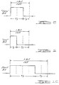
- the signals transmitted on the data bus utilize a pulse width modulation technique to represent binary logic states as well as a unique start signal.
- the bit cell time period is subdivided into three subbit-time periods. As shown in Figure 8, a "zero" (0) bit binary logic state is represented when the data bus 20 is placed in its dominant state for the first two subbit-time periods and in its passive state for the last subbit-time period.
- the 0 logic bit transmission is dominant over the 1 logic bit transmission on the bus due to the fact the second subbit-time period is energized during a 0 logic bit transmission while that same second subbit-time period of a 1 logic bit transmission should have allowed the bus to return to its passive state.
- Figure 10 illustrates the unique start signal that occupies two bit cells represented by the bus being energized to its dominant state for the first four subbit-time periods while the remaining two subbit-time periods allow the bus to return to its passive state.
- An alternative method of providing a start signal would be to energize the bus to its dominant state for the first five subbit-time periods followed by one subbit-time period with the bus in its passive state.
- the bit- wise message arbitration technique that occurs in the present invention is shown in Figure 11.
- a transmitter "A” and a transmitter “B” have attempted to transmit respective messages at approximately the same time on the data bus following a period of at least one bit cell of no bus activity.
- the transmitter A is the first to apply a start bit to the data bus.
- transmitter B since transmitter B synchronizes to the leading edge of each signal placed in the data bus, its start bit will occuratapprox- imately the same time and its synchronization will cause the rest of the B start bit and subsequent 10 bits to coincide with those transmitted by transmitter A.
- the resulting signal on the bus appears as a valid start bit and all other control modules connected to the data bus recognize the start bit and are automatically synchronized to the leading edge.
- the most significant bit in the three bit priority field of the messages transmitted by both transmitterAand transmitter B are each at a 1 logic state and therefore, the resulting logic bit signal on the bus is a 1.
- the second bit within the priority field is at a 0 logic state in the case of both transmitterAand transmitter B.
- the resulting logic bit signal on the bus is a 0.
- the transmitter A attempts to provide a 1 logic state signal to the data bus while the transmitter B provides a 0 logic state signal thereto. Since the 0 logic state signal in this embodiment dominates the 1 logic state signal, the resulting logic bit signal on the data bus will appear as a 0. Accordingly, since the transmitter A detects a bit signal which is different than that it formatted for transmission, transmitter A inhibits further transmission of its signal and transmitter B continues to transmit its message on the data bus.
- a predetermined hierarchy must be established so that messages formatted for transmission will have a known priority. For instance, on a scale of 0 to 7, brake light commands would have the highest priority.
- Safety related signals such as trunk ajar or door ajar signals, have the next level of priority.
- Subsequent order of priority in decreasing value would be the human initiated control signals, such as headlamp control, door lock controls, followed by sensor data information including fuel tank levels, ambient air temperature, speed, etc.
- the bitwise arbitration method employed herein will continue arbitration through the entire message field and will be resolved as soon as one of the transmitters provides a dominant signal different than the other.
- the arbitration will have occurred in the transmitter address portion since each transmitter has a different unique address.
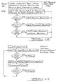
- FIG. 12 The flow diagram illustrating the operation of the control processors used to receive and transmit information throughout the network is provided in Figures 12 - 18.
- the power up and idle flow diagram is presented.
- the internal registers of the random access memories (rams) are cleared and all timers and message registers are initialized.
- the processor then waits for either a communication from its associated node processor to begin formatting and transmitting a message onto the data bus 20 or waits for a recognizable start bit to be provided from the data bus 20. If a start bit is received on the data bus 20, the control processor enters its receive routine as is described in Figures 13A - 13C.
- control processor If the control processor receives a transmit request from its local node processor, it enters its transmit routine which is described in Figures 16A and 16B. On the other hand, if the control processor receives a request for communication with its associated node processor, it enters the node communication routine shown in Figure 18.
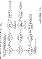
- a receive message look up subroutine is entered after the generic function field is received and stored in an appropriate register location.
- the receive message look up routine is shown in Figure 14 wherein the control field identifies either a function command (FCMD) type signal, a function data transfer (FDATA) type signal or a node-to-node (NTN) type signal is stored in the next field and compares the contents of that field received with the appropriate message type register in order to determine if the message being received is one which the corresponding control module should receive. If the message is deemed as not appropriate, the module returns to its idle state.
- FCMD function command
- FDATA function data transfer
- NTN node-to-node
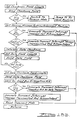
- the control module waits for a inactive bus for at least one bit cell period in order to transmit its start bit signal or the occurrence of a start bit signal from another source. In the event a start bit is detected, the control module synchronizes its current start bit and gets set to send its priority signal in the field following the start bit. If arbitration is lost during the priority field, the losing transmitter inhibits further transmission of its message and switches to a receive mode in order to receive the priority message being sent by another control module. If arbitration is not lost, the control module sends the control field followed by the generic function field, the specific function field and the unique address of the specific transmitting control module followed by a cumulative checksum field signal.
- the arbitration protocol if followed so that if a transmitting control module detects the bus being at a different logic state than that transmitted, an arbitration loss is indicated. In the event messages are not transmitted due to arbitration loss or transmitted messages are not acknowledged, the transmit mode of the control module is reset and the message is again transmitted.
Landscapes
- Engineering & Computer Science (AREA)
- Computer Networks & Wireless Communication (AREA)
- Signal Processing (AREA)
- Small-Scale Networks (AREA)
- Communication Control (AREA)
Description
- The present invention relates to the field of electrical communication networks and more specifically to the area of such networks ideally suited forthe control of electrical functions in the vehicular environment.
- Several protocols have been proposed for use in vehicle data communications over the past several years in order to efficiently replace the massive wiring harness that is presently used to provide electrical interconnection of the various switches, sensors, lights, motors, and electronic control modules located throughout the vehicle.
- One such protocol proposed in the prior art is based on Time Division Multiplexing (TDM) in which a master timing node is used as a controller to provide a synchronized set of dedicated time slots for which each slave node is obliged to synchronize with and obtain its communication data therefrom. The dedicated time slots in the TDM each provide control information of a prescribed type and those slave nodes which are programmed to perform the prescribed function must be synchronized in such a way so as to extract information from the time slot correspondingly dedicated to that function. Each "receiver" slave node must know exactly when its control function occurs in the data stream.
- Accordingly, such a system is vulnerable to a failure in the master node since, in such case, the entire network will be unable to communicate.
- In addition to the TDM's dependence on the master node operation, TDM systems generally have poor flexibility due to the limited allocation of time slots in the data stream. Accordingly, additions or deletions of types of receivers in a particular network require a reallocation of the time slots through programming of the master control node.
- TDM systems also operate on an open loop system in which there is generally no positive acknowledgment that a particular control function has been received. Consequently, TDM systems usually provide a continuous update of control data as long as a particular function is being instructed.
- Some master/slave network architectures use a polling technique. This is considered an improvement over traditional TDM systems since the master can dynamically reassign time slots. However, all network transactions are dependent on a master node and redundant master nodes are required if the system is to be reliable.
- A significant improvement over Time Division Multiplex networks is provided by a Bus Contention (BC) network architecture. A Bus Contention network is characterized by a unified system of nodes, each capable of accessing the network based on its own requirements. There are no "master" nodes, nor any dependence on any particular nodes for network operation.
- Instead of the dedicated time slots used in TDM, BC nodes have an "address" by which they are identified. This address uniquely identifies a node to all other parts of the network system. Control messages are directed by the address to the specific node that is responsible for a particular control function.
- The BC system has far greater efficiency than TDM systems because network activity is directly related to requests for activation. The bus in not burdened with the constant repetition of control signals which are not active. Messages flow between the nodes, as needed, without the intervention of a master controller. Such a method allows for greater adaptability and expandability of the network. New nodes are simply connected to the bus. No reallocation of time slots is required and existing nodes are not affected.
- A requirement for the BC type of network architecture is for media access resolution. Because all nodes are capable of network access (i.e., "transmitting") based on their individual needs, a method of resolving conflicts arising from simultaneous transmitter activations is required. Several different solutions are in widespread use for Local Area Network (LAN) applications. CSMA/CD (Carrier Sense Multiple Access with Collision Detection) and Token Passing schemes are most common. These, however, are optimized for physically (and electrically) large networks where message propagation delay between nodes is large. Collisions often are not detected until both transmitters are well into their individual message sequences. An "abort and retry" scheme is used to resolve the conflict, whereby, both messages are aborted and both transmitters must make attempts to retransmit at a later time.
- A different and more efficient method of message collision resolution has been found to be suitable for small networks. It is called the "bit-wise contention resolution" technique. An example is the Philips/Signet- ics D2B network protocol as disclosed in "The D2B a one Logical Wire Bus for Consumer Applications", by C. H. Kaplinsky, et al., IEEE Transactions on Consumer Electronics, Vol. CE-27, Feb. 1981, pg. 102 - 116; "Serial Bus Structures for Automotive Applications", by A. J. Bozzini, et al., SAE Technical Paper Series No. 830536, Feb. 28,1983; and "A Small Area Network for Cars", by R. L. Mitchell, SAE Technical Paper Series No. 840317, Feb. 1984.
- The D2B method relies on small network propagation delays, being much less than a single bit period. For a given size network, this places an upper bound on the potential frequency response or bit rate of the network. Because the network "looks" small electrically, each bit of a message exists at all points on the network simultaneously. Each transmitter, therefore, is aware of network activity on a bit-by-bit basis in real time. This allows a technique of message arbitration which resolves conflicts "on the fly". Messages are not destroyed in the arbitration process; rather, the network "sees" one of the conflicting messages as being valid. The losing transmitter detects this and tries again as soon as the first message has passed.
- The general BC network architecture described above, where each node has a unique address, is characterized by messages which have specific transmit origins and receive destinations. These "node-to-node" messages contain specific references to the physical address of both the transmitter and receiver, along with a data field which contains an encoded description of a particular activity to take place. While BC network configurations are a significant improvement over TDM systems, there are still aspects of network operations unique to automotive requirements which are not completely addressed by the node-to-node schemes.
- US-A-4 516 205 discloses a control system for data transmission network of bus configuration which permits each communication unit in turn access to the network when that communication unit finds the network available. Each data station is assigned a unique address and after each data transmission on the network, those communication units having data for transmission compare their data station addresses bit by bit to determine the communication unit having highest priority. The priority can be determined from the data station addresses themself or as a result of an algorithm which might include the address of the data stations and the address of that data station which has just completed transmission.
- An article entitled "Enhanced message addressing capabilities for computer network" (Proceeding of the IEEE, Volume 66, No. 11 November 1978 PP1517-27; J. McQuillan) discloses a computer network wherein three message addressing modes are used; 1) Logical addressing, in which a permanently assigned address denotes one or more physical addresses. This permits multiple connections from the subscriber to the network as well as other functions; 2) broadcasting addressing, in which a message is addressed to all subscribers; 3) Group addressing and multidestination addressing, in which a message carries the name of a list of addresses or the list itself.
- WO-A-8 403 020 discloses an apparatus for interfacing digital devices with a communication bus in a local-area computer network. Each device in a network is connected to the bus through a bus interface unit providing the device user with the abilitytoestab- lish a connection with another device by means of a simple CALL command that does not require the use of physical identifiers. The unit also allows the user to enter a TALK mode in which a two way conversation may be conducted over the network. A remode command allows an unattended device to be controlled from another user site and also permits one user to connect two remotely located devices. A message command allows a message to be stored and held for a remote user without the intervention of a host computer.
- Wescom/83 Proceedings 26/3 November 83, article of A Steinberg et al discloses a communication network with provision for changing master. At any given time only one device can be the master. Physically the devices are connected in a half duplex format and transmission and reception are done on the same line and messages are transferred in frames or group of bytes. A method of slave acknowledging the master is provided and the acknowledge word is the slaves address.
- According to the present invention there is provided a data transfer communication system comprising a common data bus (20), a plurality of communication control modules (30,32,34,38) each connected to said data bus (20) each control module having a unique identifying address and being programmed to perform one or more predetermined functions, and each module containing means (32b, 38b) for receiving and means (32d, 38d) for transmitting data messages from or to other control modules on said common data bus, characterised in that each of said control module includes means (32n,38n) for providing binary bit signals on said data bus having a bit length of a predetermined bit-time period with each bit-time period subdivided into at least three predetermined subbit-time periods, a first of said binary bit signals being represented by placing said data bus in its dominant state during the first subbit-time period followed by placing said data bus in its passive state for the remaining two subbit-time period of said bit-time period and a second of said binary bit signals being represented by placing said data bus in its dominant state for the first two subbit-time periods followed by placing said data bus in its passive state for the remaining subbit-time period of said bit-time period and a unique START bit signal for transmission having a length of two bit-time periods and represented by placing said data bus in its dominant state for a full bit-time period and at least the first subbit-time period of the next bit-time period, each of said means (32n,38n) being arranged to utilise said binary bit signals and said start bit signal for formatting data messages for transmission on said common data bus into one of at least two types of messages each of which includes in sequence, said common but unique START signal of a predetermined field length to indicate the start of a data message transmission, a PRIORITY signal of a second predetermined field length to indicate the code of the relative degree of priority the formatted data message has for transmission on a predetermined hierarchy of priority, a TYPE CONTROL signal of a third predetermined field length to indicate the code of which of said at least two types of data messages being formatted for transmission, a FUNCTION or RECEIVE ADDRESS signal of a fourth predetermined field length indicating the code of the function to be performed by other control modules connected to said data bus or the unique address of a specific control module receiving the data message, and each control module further including means (32c, 38c) for storing its unique identifying address and function codes of the specific predetermined functions it is p rogrammed to control, means for receiving and recognising the TYPE CONTROL signal and for receiving and recognising the FUNCTION or RECEIVE ADDRESS signal, means responsive to said TYPE CONTROL signal for comparing the received FUNCTION or RECEIVE ADDRESS signal with the stored function codes or the stored unique address code and to format and transmitting the unique address on said data bus when said comparing means indicated an identity, and to implement the received FUNCTION when the comparing means indicated an identity of the received FUNCTION signal with the stored function code
- Further according to the invention there is provided a method of transmitting data communication on a common data bus between recipients comprising the steps of:
- providing a binary bit signal format having a first of two binary bit signals defined as having a predetermined bit-time duration and each bit-time duration being subdivided into at least three predetermined subbit-time periods, a first of said binary bit signals being represented by an energization of said data bus to at least a minimum predetermined level during the first subbit-time period followed by deenergization of said data bus for the remaining two subbit-time periods of said bit-time duration and a second of said binary bit signals being represented by an energization of said data bus to at least said predetermined level during the first two subbit-time periods followed by a deenergization of said data bus for the remaining subbit-time period of said bit-time duration and a unique START bit signal represented by the energization of said data bus to at least said predetermined level forfive subbit-time periods followed by one subbit-time period of deenergization:
- providing a data transmission format utilising said binary bit signals and said START bit signal to include in sequence a START bit signal to indicate the start of a data message transmission, a PRIORITY signal of a predetermined binary bit field length to indicate the code of the relative degree of priority the formatted data message has for transmission in a predetermined hierarchy of priority, a TYPE CONTROL signal of a predetermined bit field length to indicate the code of at least two types of data messages being transmitted, a FUNCTION or RECEIVER ADDRESS signal of a predetermined bit field length respectively indicating the code of the function to be performed by a recipient of the first type of message or the unique address of a specific recipient of the second type of message, wherein said TYPE CONTROL is provided to define a first message type that is intended for one or more recipients connected to the common data bus and that the following signal field bears a functional instruction, followed by a variable acknowledgement period, or a second type of message intended for a specific recipient connected to the data bus and the following signal field bears a unique address of said specific recipient followed, by a predetermined acknowledgement period;
- providing a plurality of control modules as recipients connected to said data bus each having specific predetermined function codes and a unique address stored therein and having switchable transmitter and receiver modes or operation;
- supplying a control module with a data message;
- assembling, within said supplied control module, said message according to said data tramsmis- sion format type;
- serially energising and deenergizing said data bus according to said data transmission and binary bit signal formats
- comparing each bit transmitted by said supplied control module with the bit signal present on said data bus and inhibiting further transmission when said comparison indicated an inequality, monitoring the data but at each control module;
- recognising a START bit signal or said data bus;
- receiving and storing the PRIORITY signal;
- comparing the TYPE CONTROL along with the FUNCTION or RECEIVER ADDRESS signal with respestive stored function codes or unique address;
- switching each control module, which registers an identity in its step of comparing, to its transmitting mode of operation and transmitting its unique address on said data bus as an acknowledgement signal, and implanting the received function when said comparing indicated an identity of the received FUNCTION signal with the stored function code
- The protocol employed by the present invention allows each node to be treated as equal participants on the network since there are no specific transmitters, receivers, or timing masters. In this system, all nodes are capable of receiving and initiating commands, and informational data transfers on either a node-to-node basis or a global network transmission basis.
- The present invention utilizes a distributed control environment whereby any control module programmed as having the ability to make global (broadcast) transmission of functional commands across the network may do so and other control modules that are programmed to receive such functional commands receive, acknowledge and act on the transmitted functional commands.
- In the present invention, each function or data message includes an independent priority field wherein each type of message that is allowed to be transmitted is identified according to as predetermined priority hierarchy for bus access. The priority field guarantees network access in less than one massage period for high priority messages. High priority functions on an automotive vehicle may be, for example, a functional command from the control module monitoring brake pedal to the control modules which are preprogrammed to respond to "brake light on" functional commands and turn on the brake lights. Typically, lesser but also high priority function commands would involve the switching on of headlamps, the dimming of high beam headlamps, the actuation of door locks and the actuation of a horn.
- The present invention increases the message transmission/reception reliability by providing for a fully acknowledged communication protocol. In this system, each message period includes a positive acknowledgment portion through which each receiving control module will provide its unique address on the data bus. In this way, a systemwide handshaking technique gives positive indication to the transmitting module that the message was received and the identity of each receiver.
- Each message sent on the system is also protected by a message-wide checksum for error detection. The checksum is transmitted as part of the message and receiver acknowledgments are only made after the checksums accumulated by the receiver and in the received message are compared and found to correspond. The receiver acknowledgments are protected by a parity bit to force the receiver address to a predetermined odd or even sum.
- Message contention on the network bus is handled on a bit-wise contention basis. Therefore, for every collision of messages on the network, the one with the highest priority will win and continue to be transmitted. No bus time is lost due to collisions, because each message type is arbitrated on a bit-by-bit basis for each bit transmitted on the bus and the dominant bit prevails. This way, a valid message will be transmitted while the lower priority message is inhibited from further transmission. The losing transmitter simply waits until the higher priority message is finished before attempting to transmit. Therefore, the present invention allows for 100 % bus utilization during high traffic periods.
- The invention will now be descrived further by way of example with reference to the accompanying drawings in which:
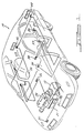
- Figure 1 is a conceptual drawing of the present invention as intended for a typical installation in an automotive vehicle.
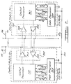
- Figure 2 is a more detailed diagram of a pair of accessory control modules connected to the data bus shown in Figure 1.
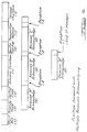
- Figure 3 illustrates the basic message format.
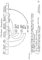
- Figure 4 illustrates the function command message format with multiple receivers acknowledging as employed in the present invention.
- Figure 5 illustrates a function data transfer message format, as employed in the present invention.
- Figure 6 illustrates a node-to-node data transfer message format, as employed in the present invention.
- Figure 7 exemplifies the method of providing checksum generation for each message.
- Figure 8 is a waveform diagram illustrating a "zero" bit signal.
- Figure 9 is a waveform diagram illustrating a "one" bit signal.
- Figure 10 is a waveform diagram illustrating a "start" bit signal.
- Figure 11 illustrates the bitwise message arbitration as it occurs in the present invention.
- Figure 12 is a flow diagram of a control processor in its power-up and idle state.
- Figure 13A- 13C provide a flow diagram of a control processor receive message routine.
- Figure 14 is a flow diagram of a control processor receive message lookup routine.
- Figure 15 is a flow diagram of a control processor transmit acknowledgment routine.
- Figures 16A and 16B provide a flow diagram of a control processor message transmit routine.
- Figure 17 is a flow diagram of a control processor receive message acknowledgment routine.
- Figure 18 is a flow diagram of a control processor node communication routine.
- The present invention is viewed as being ideally suited for installation in an automotive vehicle, such as that shown in Figure 1. In the
vehicle 10, anengine 12 is shown in order to give perspective to the overall layout of the vehicle with h respect to t he present invention. The data communication system is shown as utilizing a single databus communication link 20 that is routed to various control modules around the vehicle. In this instance, a twisted wire medium is used as thedata bus 20. However, it is foreseen that other transmission mediums such as fiber optics, acoustical carriers or coaxial cables may be substituted. - In Figure 1, a
control module 30 is illustrated as being located at the forward right corner of the vehicle. Thecontrol module 30 is intended to receive functional commands and control the operation of head- lamps, parking lamps, highbeams, turn signals, warning flasher lamps and a horn located in that general area of the vehicle. Correspondingly, acontrol module 32 in the forward left portion of the vehicle functions in a manner similar to controlmodule 30 to provide control of the various lamps at that location. Control module 34 resides on or close to theengine 12 so as to provide information from such engine mounted sensors as oil level, water temperature and engine speed to the data bus for transmission to other control modules connected theretoControl module 36 is located in the area of the instrument panel of thevehicle 10 in order to control instrument lighting and provide appropriate information to instruments thereon regarding the various sensed operational parameters within the vehicle.Control module 38 is shown connected to the steering column of thevehicle 10 and is intended to have inputs from various associated switches to control many of the functions which take place in the vehicle. For instance, headlights, parking lights, turn signals and horn actuation would most likely be controlled by switches connected to thecontrol module 38. A brake pedal sensor switch may be connected to eithercontrol module Control modules 40, 42, 50 and 52 are shown as located in the doors of thevehicle 10 to provide interconnection to the various window raising and lowering motors, the door lock actuators, door open/close sensor switches, convenience lighting and in the case of the control modules 40 and 52 on the front doors, power seat control switches. Thecontrol module 54 is shown as being located central to the vehicle, preferably under the front seats of the vehicle in order to supply control information to the seat adjustment motors and seat-belt connection sensors.Control modules 46 and 48 are shown as located in opposite corners at the rear ofvehicle 10 in order to control the functional operation of the various lamps located at the rear of the vehicle including stop lights, back up lights, running lights, turn signals, emergency flashers and to provide fuel level sensor information to the data bus. - While the above described functions are exemplary of those capable of being handled by the communication system of the present invention, it should be seen that the system is flexible enough to accommodate additional control modules or added functions to present modules, including diagnostic capabilities without reprogramming the unaffected control modules.
- The following discussion concerns the protocol employed by the present invention and illustrates the unique flexibility to accommodate such modifications.
- Figure 2 is an example of a relationship of two
control modules data bus 20. In addition, each control module is connected to a power bus 22. (Although the power bus 22 is not shown in Figure 1, it is understood that the power bits 22 would run throughout the vehicle to supply the necessary electrical power to the various accessories that are controlled by the control modules.) - In this embodiment, each wire of the
data bus 20 is biased to separate passive levels. A first wire is biased through a resister R1 to a regulated voltage supply of approximately 5 volts. The other wire of thedata bus 20 is biased through a resister R2 to ground. Therefore, in the passive state, one wire is at approximately 5 volts DC and the other wire at ground potential. Accordingly, when a logic bit signal is placed on the data bus, and the data bus is energized to its dominate state for period of time, the normally 5 volt biased line will be driven to approximately ground potential and the normally zero biased line will be driven to approximately a 5 volt level. This technique allows for increased reliability of signal transmission and reception via differential drivers and receivers. - In the configuration shown in Figure 2, each control module contains an interface circuit 321 (381) which includes a differential driver 320 (38D) and a differential receiver 32B (38B). Each control module includes a control processor 32C (38C) and node processor.
- The present embodiment of the invention utilizes Intel 8751 microcomputers for respective control and node processors. Of course the control processor, as described above, controls the network communication tasks while the node processor controls the local tasks orfunctions. While the control microprocessors on the network all utilize identical programming to accomplish the network control task, each contains a unique address to identify that particular control module and unique function codes stored in its memory that correspond to the particular functions handled by its associated node processor. The control processor, besides communicating with the network through the interface circuit, also communicates through a parallel interface with the node processor.
- The node processor interfaces with various devices in an area of its physical location through its various I/O ports to provide appropriate inter-connection to the power bus 22. Resident software in each node processor gives the particular processor a specific "personality" since each node processor controls or responds to different elements in the vehicle.
- Architecturally, the control processor appears to the node processor as a series of read/write registers which contain various status and data information. The node processor initializes and performs network transmissions by writing information to those registers and receives messages by reading other registers. All register read/write operations take place over a parallel data bus interconnecting the two processors. The process for reading and writing those registers is coordinated by the four control lines designated as "data/pointer", "read/write", "strobe" and "busy". All but the busy line are inputs to the control processor. The busy line is used to indicate that the control processor is occupied performing some task relative to the node processor interface. In order to achieve a message transmission between the control and node processors, the control processor receives through the parallel interface to the node processor, information, in byte form, to be formed into the protocol for transmission on the
data bus 20. The control processor is also responsible for recognition and decoding of formatted messages from the bus. - The basic unit of communication in the network protocol of the present invention is the message format. Each message is intended to be from 40 to 121 bits long, depending on the message type. For a five kilohertz bit clock rate, the message period requires from 8 milliseconds to 24.2 milliseconds, depending upon the message length. Typical message periods are approximately 10 milliseconds long, resulting in a 100 message per second network capacity. Of course, utilizing a higher bit clock rate would increase the message capacity of the network.
- The present invention uses two general types of messages. First, a node-to-node type message is designated with a specific transmitter and receiver address contained in the message. A second general type of message is a functional message which is intended for global broadcast distribution on the network. A first type of functional message is termed herein as a "functional command" message, where the entire message is transmitted and acknowledged as received by one or more othercontrol modules programmed to receive the particular function command contained in the message. Asecond type offunctional message is termed herein as a "functional data transfer" message which is an expansion of the functional command message to include informational data following the receiver acknowledgment portion for global distribution on the network.
- Figure 3 illustrates the basic message format as employed in the present invention. The basic format contains a message descriptor segment and a receiver acknowledgment segment. A data segment may also be provided in certain types of messages (node-to-node and functional data transfer). In the message descriptor segment, a unique start bit is first provied followed by a priority code. The priority code is utilized for message arbitration on a bitwise basis and will be discussed below with respect to Figure 11. Following the priority code, is a type control code that indicates which of the two general types of messages is being transmitted. The following field contains either function address as is employed in the broadcast functional messages or a specific receiver address in the event the message is a type intended for node-to-node communication. The following field contains the transmitter address followed by a message checksum field.
- The receiver acknowledgment segment of t he basic message format shown in Figure 3 is either variable in length, when the message type is a broadcast functional type message so as to accommodate any number of receivers attempting to acknowledge receipt of the message, or of a fixed length, if the transmitted message is a node-to-node type message to accommodate the acknowledgment by one particular receiver of its unique address.
- The data segment follows the receiver acknowledgment segment in the event the message is a node-to-node type or a functional information type and includes a string of data up to a predetermined limit.
- The present invention has the advantage of providing global network messages that can replace several node-to-node messages. On the other hand, where node-to-node messages need to carry sensor information such as engine speed, vehicle speed or temperature to a specific control module, such messages are also accommodated. In the case of a message for turning on or off emergency flashers on a vehicle, it is seen as most efficient to provide a functional command that is broadcast to all of the control modules. Only those control modules connected to the lamps which serve as emergency flashers will, of course, respond to the functional command message on a single transmission of the message. Such an accommodation eliminates the necessity to broadcast four separate node-to-node messages to control the four separately located and controlled flasher lamps.
- In order to provide a secure system, acknowledgment must be accommodated. Since there is an unspecified number of receivers that will receive and respond to a particular functional type message, the present system provides for a variable period in the receiver acknowledgment segment of each message.
- The function command message format is shown in Figure 4 as including the unique start signal occupying a two bit field. Athree bit field for the priority signal follows the start signal and a two bit field for the control signal follows the priority signal. The control signal will indicate a function command type message being transmitted. The following eleven bit field contains a generic function address in the first seven bits and a specific function address in the remaining four bits. A generic function might appear as "head-lamps" while the specific function may appear as "on" or "off'. Another generic function command may appear as "door locks" while the associated specific function may appear as "lock" or "unlock". Following the function command, a seven bit field conveys the transmitting control module's unique address while the immediately succeeding seven bit field includes the message checksum of the message. Following the end of the message checksum, the transmitting control module reverts to its receiver mode of operation to await acknowledgments by receiving control modules that are programmed to respond to the function command contained in the message. A receiver having the highest priority unique address will prevail as the first to acknowledge and, following the appropriate protocol, any other receiver that lost out in accessing the bus to transmit its acknowledgment address will change the exception bit from a passive state to a dominant state and contend for the bus to transmit its unique address as an acknowledgment. Such acknowledgment continues until all receivers of the function command have acknowledged receipt and the exception bit is left at its passive state for one bit length. At the end of the exception bit being left in a passive state for one bit length, any other control module having a message to be sent may attempt to access the bus by providing a start bit and contending for the transmission of its complete message.
- The function data transfer type message shown in Figure 5 is very similar to the function command message format shown in Figure 4 except that after the receiver acknowledgment segment of the message period is utilized, the transmitting control module reverts back to its transmitting mode of operation and transmits data in eight bit bytes. An end of data signal is followed by a data checksum signal occupying eight bits.
- The node-to-node data transfer message format is shown in Figure 6 and differs from the function data transfer message shown in Figure 5 by providing a different type signal code in the two bit control field and a specific receiver address in the seven bit field following the control field. The node-to-node data transfer message provides for a single receiver acknowledge field in the acknowledge segment followed by a number of data byte fields of eight bits each in the data segment.
- A typical need for a node-to-node type message may occur where a control module 52 is connected through its associated node processor to a set of power window control switches and the switch assigned to command the movement of the right front window is actuated. In such a case the message would be sent specifically to control module 40 which is associated with the right front window motor. In that instance, the control field would indicate a node-to-node type message is being sent, the unique address of the control module 40 would occupy the receiver field and the data field would contain instructions to move the specific window up or down. The checksum generation method is shown in Figure 7 wherein the binary values of the priority field, the control field, the function fields and the transmitter address fields are summed to provide a unique binary number which is included by the transmitting control module in the message checksum field. Accordingly, a receiving control module can compare the transmitted message checksum received with the binary signals it has accumulated to determine whether or not the received message corresponds to the message transmitted.
- The signals transmitted on the data bus utilize a pulse width modulation technique to represent binary logic states as well as a unique start signal. The bit cell time period is subdivided into three subbit-time periods. As shown in Figure 8, a "zero" (0) bit binary logic state is represented when the
data bus 20 is placed in its dominant state for the first two subbit-time periods and in its passive state for the last subbit-time period. - In Figure 9, a "one" (1) bit binary logic state is illustrated, whereby the data bus is energized to its dominant state for the first one-third of the bit cell time period and allowed to resume its passive state for the remaining two subbit-time periods.
- In this embodiment, the 0 logic bit transmission is dominant over the 1 logic bit transmission on the bus due to the fact the second subbit-time period is energized during a 0 logic bit transmission while that same second subbit-time period of a 1 logic bit transmission should have allowed the bus to return to its passive state.
- Figure 10 illustrates the unique start signal that occupies two bit cells represented by the bus being energized to its dominant state for the first four subbit-time periods while the remaining two subbit-time periods allow the bus to return to its passive state. An alternative method of providing a start signal would be to energize the bus to its dominant state for the first five subbit-time periods followed by one subbit-time period with the bus in its passive state.
- Utilizing the pulse width modulation technique of conveying binary bit signals on the data bus, the bit- wise message arbitration technique that occurs in the present invention is shown in Figure 11. In that Figure 11, a transmitter "A" and a transmitter "B" have attempted to transmit respective messages at approximately the same time on the data bus following a period of at least one bit cell of no bus activity. In Figure 11, it is assumed the transmitter A is the first to apply a start bit to the data bus. However, since transmitter B synchronizes to the leading edge of each signal placed in the data bus, its start bit will occuratapprox- imately the same time and its synchronization will cause the rest of the B start bit and subsequent 10 bits to coincide with those transmitted by transmitter A. The resulting signal on the bus appears as a valid start bit and all other control modules connected to the data bus recognize the start bit and are automatically synchronized to the leading edge.
- In the example shown in Figure 11, the most significant bit in the three bit priority field of the messages transmitted by both transmitterAand transmitter B are each at a 1 logic state and therefore, the resulting logic bit signal on the bus is a 1. The second bit within the priority field is at a 0 logic state in the case of both transmitterAand transmitter B. The resulting logic bit signal on the bus is a 0. However, in the least significant bit portion of the priority field, the transmitter A attempts to provide a 1 logic state signal to the data bus while the transmitter B provides a 0 logic state signal thereto. Since the 0 logic state signal in this embodiment dominates the 1 logic state signal, the resulting logic bit signal on the data bus will appear as a 0. Accordingly, since the transmitter A detects a bit signal which is different than that it formatted for transmission, transmitter A inhibits further transmission of its signal and transmitter B continues to transmit its message on the data bus.
- With respect to the issue of priority, a predetermined hierarchy must be established so that messages formatted for transmission will have a known priority. For instance, on a scale of 0 to 7, brake light commands would have the highest priority. Safety related signals, such as trunk ajar or door ajar signals, have the next level of priority. Subsequent order of priority in decreasing value would be the human initiated control signals, such as headlamp control, door lock controls, followed by sensor data information including fuel tank levels, ambient air temperature, speed, etc.
- In the event two transmitters provide the same priority message at the same time to the data bus, the bitwise arbitration method employed herein, will continue arbitration through the entire message field and will be resolved as soon as one of the transmitters provides a dominant signal different than the other. In the case of duplicate priority transmissions with duplicate functions, the arbitration will have occurred in the transmitter address portion since each transmitter has a different unique address.
- The flow diagram illustrating the operation of the control processors used to receive and transmit information throughout the network is provided in Figures 12 - 18. In Figure 12, the power up and idle flow diagram is presented. Upon power up, the internal registers of the random access memories (rams) are cleared and all timers and message registers are initialized. The processor then waits for either a communication from its associated node processor to begin formatting and transmitting a message onto the
data bus 20 or waits for a recognizable start bit to be provided from thedata bus 20. If a start bit is received on thedata bus 20, the control processor enters its receive routine as is described in Figures 13A - 13C. If the control processor receives a transmit request from its local node processor, it enters its transmit routine which is described in Figures 16A and 16B. On the other hand, if the control processor receives a request for communication with its associated node processor, it enters the node communication routine shown in Figure 18. - In the receive message routine, a receive message look up subroutine is entered after the generic function field is received and stored in an appropriate register location. The receive message look up routine is shown in Figure 14 wherein the control field identifies either a function command (FCMD) type signal, a function data transfer (FDATA) type signal or a node-to-node (NTN) type signal is stored in the next field and compares the contents of that field received with the appropriate message type register in order to determine if the message being received is one which the corresponding control module should receive. If the message is deemed as not appropriate, the module returns to its idle state. On the other hand, if the message is found in the appropriate register and the checksum field is verified, an acknowledgment is made and the routine then notifies the associated node processor it has received a message and will transfer the same. In the transmit acknowledgment routine shown in Figure 15, the receiving control module provides its own unique "node" address in the appropriate acknowledgment field. However, if arbitration is lost it will continue to attempt access and transmit its node address for a predetermined number of times before giving up.
- In the transmit routine shown in
Figures 16Aand 16B, the control module waits for a inactive bus for at least one bit cell period in order to transmit its start bit signal or the occurrence of a start bit signal from another source. In the event a start bit is detected, the control module synchronizes its current start bit and gets set to send its priority signal in the field following the start bit. If arbitration is lost during the priority field, the losing transmitter inhibits further transmission of its message and switches to a receive mode in order to receive the priority message being sent by another control module. If arbitration is not lost, the control module sends the control field followed by the generic function field, the specific function field and the unique address of the specific transmitting control module followed by a cumulative checksum field signal. In each case of sending the particular fields, the arbitration protocol if followed so that if a transmitting control module detects the bus being at a different logic state than that transmitted, an arbitration loss is indicated. In the event messages are not transmitted due to arbitration loss or transmitted messages are not acknowledged, the transmit mode of the control module is reset and the message is again transmitted.
Claims (5)
Applications Claiming Priority (2)
| Application Number | Priority Date | Filing Date | Title |
|---|---|---|---|
| US06/779,200 US4715031A (en) | 1985-09-23 | 1985-09-23 | Vehicular data transfer communication system |
| US779200 | 1985-09-23 |
Publications (4)
| Publication Number | Publication Date |
|---|---|
| EP0217571A2 EP0217571A2 (en) | 1987-04-08 |
| EP0217571A3 EP0217571A3 (en) | 1988-06-01 |
| EP0217571B1 EP0217571B1 (en) | 1989-12-27 |
| EP0217571B2 true EP0217571B2 (en) | 1993-05-05 |
Family
ID=25115646
Family Applications (1)
| Application Number | Title | Priority Date | Filing Date |
|---|---|---|---|
| EP86306980A Expired - Lifetime EP0217571B2 (en) | 1985-09-23 | 1986-09-10 | Data transfer communication system |
Country Status (5)
| Country | Link |
|---|---|
| US (1) | US4715031A (en) |
| EP (1) | EP0217571B2 (en) |
| JP (1) | JPH0626335B2 (en) |
| CA (1) | CA1261935A (en) |
| DE (1) | DE3667891D1 (en) |
Families Citing this family (102)
| Publication number | Priority date | Publication date | Assignee | Title |
|---|---|---|---|---|
| DE3546664C3 (en) * | 1985-02-22 | 1995-10-26 | Bosch Gmbh Robert | Method for operating a data processing system |
| DE3534216A1 (en) * | 1985-09-25 | 1987-04-02 | Bayerische Motoren Werke Ag | DATA BUS SYSTEM FOR VEHICLES |
| US4896261A (en) * | 1986-11-24 | 1990-01-23 | Motorola Inc. | System for scheduling serial message transmission on a bus which is adoptable for rescheduling prioritized messages using a doubly-linked list |
| NL8700736A (en) * | 1987-03-30 | 1988-10-17 | Philips Nv | ONE-CHANNEL BUS SYSTEM FOR MASTER MASTER USE, WITH BIT CELL SYNCHRONIZATION, AND MASTER STATION FITTED WITH A BIT CELL SYNCHRONIZATION ELEMENT. |
| JPH0771088B2 (en) * | 1987-04-06 | 1995-07-31 | 古河電気工業株式会社 | Multiplex transmission system |
| JP2502310B2 (en) * | 1987-05-21 | 1996-05-29 | 日本電装株式会社 | Control device having communication function |
| US4768189A (en) * | 1987-06-17 | 1988-08-30 | Bell Communications Research, Inc. | High capacity communication utilizing static, OR-type channels |
| DE3730468A1 (en) * | 1987-09-08 | 1989-03-16 | Bergmann Kabelwerke Ag | ON-BOARD NETWORK FOR MOTOR VEHICLES AND METHOD FOR OPERATING THE ON-BOARD NETWORK |
| US5107256A (en) * | 1987-11-02 | 1992-04-21 | Matsushita Electric Industrial Co., Ltd. | Method and apparatus for controlling terminals on communication network |
| US4951281A (en) * | 1987-11-30 | 1990-08-21 | Furukawa Electric Co., Ltd. | Multiplex transmission system |
| US4939725A (en) * | 1987-11-30 | 1990-07-03 | Furukawa Electric Co., Ltd. | Multiplex transmission system |
| NL8800639A (en) * | 1988-03-16 | 1989-10-16 | Philips Nv | ONE-CHANNEL COMMUNICATION BUS SYSTEM AND STATION FOR USE IN SUCH A COMMUNICATION BUS SYSTEM. |
| US5249182A (en) * | 1988-03-16 | 1993-09-28 | U.S. Philips Corporation | Communication bus system with lock/unlock capability |
| FI81225C (en) * | 1988-09-30 | 1990-09-10 | Kone Oy | FOERFARANDE OCH ANORDNING FOER ATT SAENDA MEDDELANDE I BINAERFORM I EN SERIETRAFIKBUSS. |
| JP2771556B2 (en) * | 1988-10-31 | 1998-07-02 | 古河電気工業株式会社 | Multiplex transmission equipment for vehicles |
| US4907223A (en) * | 1988-12-07 | 1990-03-06 | Chrysler Motors Corporation | Electrical devices command system, single wire bus and smart quad controller arrangement therefor |
| US4920532A (en) * | 1988-12-07 | 1990-04-24 | Chrysler Corporation | Electrical device command system, single wire bus and smart single controller arrangement therefor |
| US4908822A (en) * | 1988-12-07 | 1990-03-13 | Chrysler Motors Corporation | Electrical devices command system, single wire bus and smart dual controller arrangement therefor |
| FR2642244B1 (en) * | 1989-01-24 | 1991-05-03 | Peugeot | METHOD AND DEVICE FOR HIERARCHISED ACCESS TO AN INFORMATION TRANSMISSION NETWORK |
| JP2771662B2 (en) * | 1989-02-21 | 1998-07-02 | キヤノン株式会社 | Image recording device |
| IT1232090B (en) * | 1989-05-04 | 1992-01-23 | Sgs Thomson Microelectronics | CONNECTION SYSTEM BETWEEN A MAIN PROCESSING UNIT AND THE PERIPHERAL UNITS |
| IT1232089B (en) * | 1989-05-04 | 1992-01-23 | Sgs Thomson Microelectronics | COMMUNICATION SYSTEM BETWEEN A MAIN PROCESSING UNIT AND PERIPHERAL UNITS |
| US5027349A (en) * | 1989-05-10 | 1991-06-25 | Alcatel Na | Embedded control technique for distributed control systems |
| AU626198B2 (en) * | 1989-05-10 | 1992-07-23 | Alcatel N.V. | Embedded control technique for distributed control systems |
| JP2904298B2 (en) * | 1990-03-30 | 1999-06-14 | マツダ株式会社 | Multiplex transmission equipment for vehicles |
| JP3082282B2 (en) * | 1990-05-21 | 2000-08-28 | 株式会社デンソー | In-vehicle communication device |
| EP0475406B1 (en) * | 1990-09-13 | 1997-04-23 | Mazda Motor Corporation | Multiplex transmission system for vehicles |
| JP3100975B2 (en) * | 1990-10-25 | 2000-10-23 | パイオニア株式会社 | Data communication system |
| DE59009700D1 (en) * | 1990-12-08 | 1995-10-26 | Itt Ind Gmbh Deutsche | Master-slave data transmission method with flexible single-wire bus. |
| DE69125924T2 (en) * | 1991-01-14 | 1997-11-20 | Philips Electronics Nv | Local communication system and frame pictures including a programmable address generator |
| JP2857501B2 (en) * | 1991-02-18 | 1999-02-17 | マツダ株式会社 | Multiplex transmission equipment |
| JP3011521B2 (en) * | 1991-03-28 | 2000-02-21 | 矢崎総業株式会社 | Electric wiring structure for vehicles |
| JPH04305754A (en) * | 1991-04-02 | 1992-10-28 | Furukawa Electric Co Ltd:The | Multiplex transmission method |
| KR100201580B1 (en) * | 1991-04-02 | 1999-06-15 | 후루까와 준노스께 | Multi Transmission System |
| FR2678085B1 (en) * | 1991-06-24 | 1995-04-14 | Sgs Thomson Microelectronics | METHOD FOR MANAGING TRANSMISSION OF INFORMATION ON AN ELECTRICAL DISTRIBUTION CIRCUIT, DEVICE FOR ITS IMPLEMENTATION AND APPLICATION OF THE PROCESS TO COMMUNICATIONS IN A HOME AUTOMATION SYSTEM. |
| US5379292A (en) * | 1991-07-08 | 1995-01-03 | Naldec Corporation | Apparatus having priority order storages for recovery from failure of multiplex data transmission |
| JP2753915B2 (en) * | 1992-03-25 | 1998-05-20 | 三菱電機株式会社 | Communication control device |
| US5274636A (en) * | 1992-04-20 | 1993-12-28 | Chrysler Corporation | Automatic multiplex data link system, symbol encoder decoder therefor |
| WO1993022857A1 (en) * | 1992-05-04 | 1993-11-11 | Ford Motor Company Limited | Slave bus controller circuit for class a motor vehicle data communications |
| JPH0685874A (en) * | 1992-09-02 | 1994-03-25 | Honda Motor Co Ltd | Data communication system |
| JP3266331B2 (en) * | 1992-10-09 | 2002-03-18 | 富士通株式会社 | Output circuit |
| JP2844036B2 (en) * | 1992-10-20 | 1999-01-06 | 三菱電機株式会社 | Communication control device |
| US5507002A (en) * | 1992-12-24 | 1996-04-09 | At&T Global Information Solutions Company | Peripheral component interconnect special cycle protocol using soft message IDS |
| DE69428930T2 (en) * | 1993-02-15 | 2002-06-27 | Honda Giken Kogyo K.K., Tokio/Tokyo | Method and device for transmitting data |
| US5406091A (en) * | 1993-05-27 | 1995-04-11 | Ford Motor Company | Communication network optical isolation circuit |
| JP3402498B2 (en) * | 1993-12-24 | 2003-05-06 | パイオニア株式会社 | Automotive electronics |
| JPH07193879A (en) * | 1993-12-27 | 1995-07-28 | Alpine Electron Inc | Survival method of same address unit |
| US5625350A (en) * | 1993-12-27 | 1997-04-29 | Alpine Electronics, Inc. | Audio/video communication system and method |
| DE19514696B4 (en) * | 1994-04-18 | 2006-03-09 | Kvaser Consultant Ab | A system for eliminating interference or for enabling high-speed transmission in a serial bus circuit and transceivers connected to the latter |
| DE4429953B4 (en) * | 1994-08-24 | 2012-06-06 | Wabco Gmbh | Serial bus system |
| US5579299A (en) * | 1994-12-16 | 1996-11-26 | Chrysler Corporation | Communications network, a dual mode data transfer system therefor |
| JPH08204784A (en) * | 1995-01-31 | 1996-08-09 | Mitsubishi Denki Semiconductor Software Kk | Microcomputer with built-in serial input / output circuit |
| KR19980082163A (en) * | 1995-07-25 | 1998-12-05 | 조진영 | Multidrop Communication Network and Control Method with Dynamic Communication Speed |
| US5848277A (en) * | 1996-02-12 | 1998-12-08 | Ford Motor Company | Method for providing both level-sensitive and edge-sensitive interrupt signals on a serial interface between a peripheral and host |
| US5881063A (en) * | 1996-04-08 | 1999-03-09 | Ford Motor Company | Half-message based multiplex communication interface circuit which uses a main microcontroller to detect a match in addresses and generate a qualified signal |
| DE19634567B4 (en) * | 1996-08-27 | 2007-11-29 | Robert Bosch Gmbh | Electric brake system |
| DE19720400B4 (en) * | 1996-09-07 | 2009-09-17 | Bayerische Motoren Werke Aktiengesellschaft | Data bus for vehicles with several occupant safety devices |
| JP3117000B2 (en) * | 1997-02-21 | 2000-12-11 | 株式会社デンソー | Communication system and electronic control device used therein |
| US6324592B1 (en) | 1997-02-25 | 2001-11-27 | Keystone Aerospace | Apparatus and method for a mobile computer architecture and input/output management system |
| ES2147495B1 (en) * | 1997-07-30 | 2001-04-01 | Mecanismos Aux Es Ind S L | METHOD FOR IMPROVING THE CHARACTERISTICS OF ELECTROMAGNETIC COMPATIBILITY IN DIFFERENTIAL COMMUNICATION SYSTEMS. |
| RU2124811C1 (en) * | 1997-08-19 | 1999-01-10 | Савченков Юрий Петрович | Device for multiplex information exchange in industrial communication network |
| US6385210B1 (en) | 1998-04-17 | 2002-05-07 | Ford Global Technologies, Inc. | Method for detecting and resolving data corruption in a UART based communication network |
| JPH11341020A (en) * | 1998-05-22 | 1999-12-10 | Yazaki Corp | Multiplex communication system |
| US6275167B1 (en) | 1998-06-08 | 2001-08-14 | Visteon Global Technologies, Inc. | Method and system for communicating between remote-controlled modules in automotive vehicles |
| US6731020B2 (en) * | 2000-02-28 | 2004-05-04 | Delphi Technologies, Inc. | Column electronics control assembly |
| US6484082B1 (en) * | 2000-05-24 | 2002-11-19 | General Motors Corporation | In-vehicle network management using virtual networks |
| DE10034693A1 (en) * | 2000-07-17 | 2002-02-07 | Siemens Ag | Data transmission procedures |
| US20020065973A1 (en) * | 2000-11-30 | 2002-05-30 | Holfelner Brian K. | Method and a apparatus for transmitting data on a can data link |
| EP1396771B1 (en) * | 2001-05-31 | 2016-02-17 | Omron Corporation | Slave units and network system as well as slave unit processing method and device information collecting method |
| US7162311B2 (en) * | 2001-05-31 | 2007-01-09 | Omron Corporation | Safety network system, safety slaves unit, safety controller and communication method and information collecting method and monitoring method for the safety network system |
| US7430451B2 (en) * | 2001-05-31 | 2008-09-30 | Omron Corporation | Safety unit, controller system, connection method of controllers, control method of the controller system and monitor method of the controller system |
| WO2003001749A1 (en) * | 2001-06-22 | 2003-01-03 | Omron Corporation | Safety network system and safety slave |
| US7050860B2 (en) * | 2001-06-22 | 2006-05-23 | Omron Corporation | Safety network system, safety slave, and communication method |
| EP1406134B1 (en) * | 2001-06-22 | 2010-10-06 | Omron Corporation | Safety network system, safety slave and safety controller |
| DE10148069A1 (en) * | 2001-09-28 | 2003-04-10 | Ibeo Automobile Sensor Gmbh | Object detection and tracking procedures |
| JP3988559B2 (en) * | 2002-07-18 | 2007-10-10 | オムロン株式会社 | COMMUNICATION SYSTEM, COMMUNICATION DEVICE, AND COMMUNICATION CONTROL METHOD |
| DE10258469B4 (en) * | 2002-12-09 | 2013-10-02 | Volkswagen Ag | Method and device for data transmission in a distributed system |
| US7231467B2 (en) * | 2003-11-17 | 2007-06-12 | Agere Systems Inc. | Method and apparatus for providing an inter integrated circuit interface with an expanded address range and efficient priority-based data throughput |
| DE102004013629B4 (en) * | 2004-03-19 | 2023-06-01 | Volkswagen Ag | Communication system for a motor vehicle |
| US7882424B2 (en) * | 2005-07-29 | 2011-02-01 | GM Global Technology Operations LLC | Serial data communication—CAN memory error detection methods |
| US20070050095A1 (en) * | 2005-09-01 | 2007-03-01 | Polaris Industries Inc. | Controller area network based self-configuring vehicle management system and method |
| EP1881409A1 (en) * | 2006-07-18 | 2008-01-23 | Siemens Aktiengesellschaft | Rapid Prototyping Unit |
| US7669682B2 (en) * | 2007-01-17 | 2010-03-02 | Polaris Industries Inc. | Rear suspension for a two wheeled vehicle |
| USD567715S1 (en) | 2007-01-17 | 2008-04-29 | Polaris Industries Inc. | Motorcycle |
| US7748746B2 (en) | 2007-01-17 | 2010-07-06 | Polaris Industries Inc. | Fuel tank arrangement for a vehicle |
| US20100087981A1 (en) * | 2008-10-02 | 2010-04-08 | Daniel Guadalupe Orozco-Perez | Versatile vehicular care assistant system and method |
| US8994494B2 (en) * | 2008-10-10 | 2015-03-31 | Polaris Industries Inc. | Vehicle security system |
| US20110055292A1 (en) * | 2009-09-03 | 2011-03-03 | Dinu Petre Madau | System and method for standardizing vehicle network data across vehicle product lines |
| DE102010023569A1 (en) * | 2010-06-08 | 2011-12-08 | Siemens Aktiengesellschaft | Distributed communication system for power switch, has transmitting controllers for outputting addresses of receiving controllers to bus, where arbitration of controllers takes place over priority of data transmission |
| JP5922350B2 (en) * | 2011-08-03 | 2016-05-24 | 株式会社デンソー | Communication system, transceiver |
| US10345108B2 (en) | 2012-05-16 | 2019-07-09 | Polaris Industries Inc. | System and method for multi-plane routing |
| CN105074385B (en) | 2013-02-26 | 2019-09-10 | 北极星工业有限公司 | Lie fallow the telemetering of vehicle interactive mode, mapping and schedule planning system |
| US9324195B2 (en) | 2013-02-26 | 2016-04-26 | Polaris Industries Inc. | Recreational vehicle interactive, telemetry, mapping, and trip planning system |
| US11209286B2 (en) | 2013-02-26 | 2021-12-28 | Polaris Industies Inc. | Recreational vehicle interactive telemetry, mapping and trip planning system |
| WO2014149089A1 (en) * | 2013-03-18 | 2014-09-25 | Rolls-Royce Corporation | Deterministic ethernet for an aerospace distributed control system |
| JP6027046B2 (en) * | 2014-04-14 | 2016-11-16 | 株式会社日本自動車部品総合研究所 | Communications system |
| US10305671B2 (en) * | 2015-05-21 | 2019-05-28 | Cirrus Logic, Inc. | Synchronous differential signaling protocol |
| US10038977B2 (en) | 2016-02-10 | 2018-07-31 | Polaris Industries Inc. | Recreational vehicle group management system |
| US11400997B2 (en) | 2016-05-23 | 2022-08-02 | Indian Motorcycle International, LLC | Display systems and methods for a recreational vehicle |
| US10274331B2 (en) | 2016-09-16 | 2019-04-30 | Polaris Industries Inc. | Device and method for improving route planning computing devices |
| US10783026B2 (en) * | 2018-02-15 | 2020-09-22 | Honeywell International Inc. | Apparatus and method for detecting network problems on redundant token bus control network using traffic sensor |
| US11531333B2 (en) | 2020-04-14 | 2022-12-20 | Polaris Industries Inc. | Communication and relay systems for vehicles |
Citations (2)
| Publication number | Priority date | Publication date | Assignee | Title |
|---|---|---|---|---|
| WO1984003020A1 (en) † | 1983-01-26 | 1984-08-02 | Trw Inc | Communication bus interface unit |
| US4516205A (en) † | 1982-11-09 | 1985-05-07 | Eing A Hubert I | Access control of data transmission network |
Family Cites Families (21)
| Publication number | Priority date | Publication date | Assignee | Title |
|---|---|---|---|---|
| US3363059A (en) * | 1963-09-20 | 1968-01-09 | William L Paddison | Start-stop communication system for use in space reservation and the like |
| CH527547A (en) * | 1971-08-13 | 1972-08-31 | Ibm | Method for information transmission with a priority scheme in a time division multiplex message transmission system with a ring line |
| GB1365838A (en) * | 1972-04-21 | 1974-09-04 | Ibm | Data handling system |
| US4063220A (en) * | 1975-03-31 | 1977-12-13 | Xerox Corporation | Multipoint data communication system with collision detection |
| CA1086397A (en) * | 1976-09-14 | 1980-09-23 | Charles G. Diefenderfer | Polling an data communication system having a pulse position to binary address conversion circuit |
| FR2390854A1 (en) * | 1977-05-13 | 1978-12-08 | Cometa Sa | Binary coded data transmission system - uses electronic or optical pulses and time duration modulation of serial data |
| US4161786A (en) * | 1978-02-27 | 1979-07-17 | The Mitre Corporation | Digital bus communications system |
| US4271507A (en) * | 1979-06-07 | 1981-06-02 | Ford Motor Company | Communication broadcast channel interface |
| US4234952A (en) * | 1979-06-07 | 1980-11-18 | Ford Motor Company | Conflict resolution by retransmission delay on shared communication medium |
| JPS6041372B2 (en) * | 1979-07-19 | 1985-09-17 | 株式会社明電舎 | Connection method for multiple data processing devices |
| DE3009308A1 (en) * | 1980-03-11 | 1981-10-01 | Siemens AG, 1000 Berlin und 8000 München | METHOD AND ARRANGEMENT FOR TRANSMITTING DATA SIGNALS |
| DE3269432D1 (en) * | 1981-10-15 | 1986-04-03 | Nat Res Dev | Data-packet driven digital computer |
| US4425564A (en) * | 1981-11-04 | 1984-01-10 | General Motors Corporation | Multiplex wiring system for motor vehicles |
| US4482951A (en) * | 1981-11-12 | 1984-11-13 | Hughes Aircraft Company | Direct memory access method for use with a multiplexed data bus |
| US4439856A (en) * | 1982-02-24 | 1984-03-27 | General Electric Company | Bimodal bus accessing system |
| US4506360A (en) * | 1982-03-29 | 1985-03-19 | Gould Inc. | Multi-station token pass communication system and method |
| JPS58195350A (en) * | 1982-05-10 | 1983-11-14 | Fuji Electric Co Ltd | Data transmission system |
| JPS59132037A (en) * | 1983-01-14 | 1984-07-30 | Hitachi Ltd | Initial setting method of terminal device |
| DE3335932A1 (en) * | 1983-10-04 | 1985-04-18 | Wabco Westinghouse Fahrzeugbremsen GmbH, 3000 Hannover | DEVICE FOR INQUIRING AND CONTROLLING SEVERAL COMPONENTS OF A VEHICLE |
| GB8331974D0 (en) * | 1983-11-30 | 1984-01-04 | Lucas Elect Electron Syst | Vehicle multiplex system |
| US4570257A (en) * | 1984-02-14 | 1986-02-11 | Rosemount Inc. | Communication system with slot time error detection |
-
1985
- 1985-09-23 US US06/779,200 patent/US4715031A/en not_active Expired - Lifetime
-
1986
- 1986-07-03 CA CA000513031A patent/CA1261935A/en not_active Expired
- 1986-08-05 JP JP61184119A patent/JPH0626335B2/en not_active Expired - Lifetime
- 1986-09-10 EP EP86306980A patent/EP0217571B2/en not_active Expired - Lifetime
- 1986-09-10 DE DE8686306980T patent/DE3667891D1/en not_active Expired - Fee Related
Patent Citations (2)
| Publication number | Priority date | Publication date | Assignee | Title |
|---|---|---|---|---|
| US4516205A (en) † | 1982-11-09 | 1985-05-07 | Eing A Hubert I | Access control of data transmission network |
| WO1984003020A1 (en) † | 1983-01-26 | 1984-08-02 | Trw Inc | Communication bus interface unit |
Non-Patent Citations (1)
| Title |
|---|
| R. L. MITCHELL: 'A Small Area Network for Cars' SAE TECHNICAL PAPER SERIES no. 840317, February 1984, † |
Also Published As
| Publication number | Publication date |
|---|---|
| CA1261935A (en) | 1989-09-26 |
| EP0217571B1 (en) | 1989-12-27 |
| US4715031A (en) | 1987-12-22 |
| EP0217571A2 (en) | 1987-04-08 |
| JPS6268337A (en) | 1987-03-28 |
| EP0217571A3 (en) | 1988-06-01 |
| DE3667891D1 (en) | 1990-02-01 |
| JPH0626335B2 (en) | 1994-04-06 |
Similar Documents
| Publication | Publication Date | Title |
|---|---|---|
| EP0217571B2 (en) | Data transfer communication system | |
| CN114666183B (en) | Communication method and corresponding system and device | |
| EP3913864B1 (en) | A method of operating a communication bus, corresponding system, devices and vehicle | |
| US4914654A (en) | Multiplex transmission system | |
| KR100201580B1 (en) | Multi Transmission System | |
| EP0396090B1 (en) | System for communication between a master and slave processing units | |
| US5343475A (en) | Multiplex transmission system | |
| US6777825B1 (en) | Data transmission method and system in a motor vehicle occupant protection system | |
| JPH03283844A (en) | Multiplex transmission equipment for vehicle | |
| US5065153A (en) | Contention control system | |
| JP2638009B2 (en) | Multiplex transmission method | |
| JPH0828725B2 (en) | Multiplex transmission system | |
| JP2781397B2 (en) | Multiplex transmission equipment | |
| JP3133514B2 (en) | Multiplex transmission method | |
| JPH01233134A (en) | Breakage detection device for vehicles | |
| JP3281734B2 (en) | Multiplex communication system | |
| JPH01143535A (en) | Multiplex transmission system | |
| JP2926934B2 (en) | Communication device | |
| Pattantyus | Multiplexed data link with token passing | |
| JPH04227352A (en) | Multiplex transmission system | |
| JPH05207033A (en) | Multiplexer |
Legal Events
| Date | Code | Title | Description |
|---|---|---|---|
| PUAI | Public reference made under article 153(3) epc to a published international application that has entered the european phase |
Free format text: ORIGINAL CODE: 0009012 |
|
| AK | Designated contracting states |
Kind code of ref document: A2 Designated state(s): DE FR GB |
|
| PUAL | Search report despatched |
Free format text: ORIGINAL CODE: 0009013 |
|
| AK | Designated contracting states |
Kind code of ref document: A3 Designated state(s): DE FR GB |
|
| 17P | Request for examination filed |
Effective date: 19880623 |
|
| 17Q | First examination report despatched |
Effective date: 19880913 |
|
| GRAA | (expected) grant |
Free format text: ORIGINAL CODE: 0009210 |
|
| AK | Designated contracting states |
Kind code of ref document: B1 Designated state(s): DE FR GB |
|
| REF | Corresponds to: |
Ref document number: 3667891 Country of ref document: DE Date of ref document: 19900201 |
|
| ET | Fr: translation filed | ||
| REG | Reference to a national code |
Ref country code: GB Ref legal event code: 746 |
|
| PLBE | No opposition filed within time limit |
Free format text: ORIGINAL CODE: 0009261 |
|
| PLAA | Information modified related to event that no opposition was filed |
Free format text: ORIGINAL CODE: 0009299DELT |
|
| PLBE | No opposition filed within time limit |
Free format text: ORIGINAL CODE: 0009261 |
|
| PLBI | Opposition filed |
Free format text: ORIGINAL CODE: 0009260 |
|
| PLAA | Information modified related to event that no opposition was filed |
Free format text: ORIGINAL CODE: 0009299DELT |
|
| 26N | No opposition filed | ||
| 26 | Opposition filed |
Opponent name: N.V. PHILIPS' GLOEILAMPENFABRIEKEN Effective date: 19900927 |
|
| 26N | No opposition filed | ||
| REG | Reference to a national code |
Ref country code: FR Ref legal event code: DL |
|
| PUAH | Patent maintained in amended form |
Free format text: ORIGINAL CODE: 0009272 |
|
| STAA | Information on the status of an ep patent application or granted ep patent |
Free format text: STATUS: PATENT MAINTAINED AS AMENDED |
|
| 27A | Patent maintained in amended form |
Effective date: 19930505 |
|
| AK | Designated contracting states |
Kind code of ref document: B2 Designated state(s): DE FR GB |
|
| EN3 | Fr: translation not filed ** decision concerning opposition | ||
| REG | Reference to a national code |
Ref country code: FR Ref legal event code: R1 |
|
| ET3 | Fr: translation filed ** decision concerning opposition | ||
| REG | Reference to a national code |
Ref country code: FR Ref legal event code: DS |
|
| REG | Reference to a national code |
Ref country code: FR Ref legal event code: TP Ref country code: FR Ref legal event code: CD |
|
| PGFP | Annual fee paid to national office [announced via postgrant information from national office to epo] |
Ref country code: GB Payment date: 20010814 Year of fee payment: 16 |
|
| PGFP | Annual fee paid to national office [announced via postgrant information from national office to epo] |
Ref country code: DE Payment date: 20010903 Year of fee payment: 16 |
|
| PGFP | Annual fee paid to national office [announced via postgrant information from national office to epo] |
Ref country code: FR Payment date: 20010904 Year of fee payment: 16 |
|
| REG | Reference to a national code |
Ref country code: GB Ref legal event code: IF02 |
|
| PG25 | Lapsed in a contracting state [announced via postgrant information from national office to epo] |
Ref country code: GB Free format text: LAPSE BECAUSE OF NON-PAYMENT OF DUE FEES Effective date: 20020910 |
|
| PG25 | Lapsed in a contracting state [announced via postgrant information from national office to epo] |
Ref country code: DE Free format text: LAPSE BECAUSE OF NON-PAYMENT OF DUE FEES Effective date: 20030401 |
|
| GBPC | Gb: european patent ceased through non-payment of renewal fee |
Effective date: 20020910 |
|
| PG25 | Lapsed in a contracting state [announced via postgrant information from national office to epo] |
Ref country code: FR Free format text: LAPSE BECAUSE OF NON-PAYMENT OF DUE FEES Effective date: 20030603 |
|
| REG | Reference to a national code |
Ref country code: FR Ref legal event code: ST |