EP0217550A1 - Galvanic cell - Google Patents
Galvanic cell Download PDFInfo
- Publication number
- EP0217550A1 EP0217550A1 EP86306756A EP86306756A EP0217550A1 EP 0217550 A1 EP0217550 A1 EP 0217550A1 EP 86306756 A EP86306756 A EP 86306756A EP 86306756 A EP86306756 A EP 86306756A EP 0217550 A1 EP0217550 A1 EP 0217550A1
- Authority
- EP
- European Patent Office
- Prior art keywords
- lugs
- strip
- stack
- plates
- aligned
- Prior art date
- Legal status (The legal status is an assumption and is not a legal conclusion. Google has not performed a legal analysis and makes no representation as to the accuracy of the status listed.)
- Withdrawn
Links
- 238000011065 in-situ storage Methods 0.000 claims abstract description 4
- 230000008878 coupling Effects 0.000 abstract 1
- 238000010168 coupling process Methods 0.000 abstract 1
- 238000005859 coupling reaction Methods 0.000 abstract 1
- 239000000463 material Substances 0.000 description 6
- 238000005192 partition Methods 0.000 description 6
- 238000004519 manufacturing process Methods 0.000 description 5
- 229920003002 synthetic resin Polymers 0.000 description 5
- 239000000057 synthetic resin Substances 0.000 description 5
- 239000011810 insulating material Substances 0.000 description 4
- 238000000034 method Methods 0.000 description 4
- 238000000465 moulding Methods 0.000 description 4
- 239000002253 acid Substances 0.000 description 3
- YADSGOSSYOOKMP-UHFFFAOYSA-N dioxolead Chemical compound O=[Pb]=O YADSGOSSYOOKMP-UHFFFAOYSA-N 0.000 description 3
- 239000012212 insulator Substances 0.000 description 3
- 238000003860 storage Methods 0.000 description 3
- 229920001187 thermosetting polymer Polymers 0.000 description 3
- 238000004873 anchoring Methods 0.000 description 2
- 239000003292 glue Substances 0.000 description 2
- 239000002184 metal Substances 0.000 description 2
- 229920005989 resin Polymers 0.000 description 2
- 239000011347 resin Substances 0.000 description 2
- 238000007493 shaping process Methods 0.000 description 2
- 230000035939 shock Effects 0.000 description 2
- 229920001169 thermoplastic Polymers 0.000 description 2
- 239000004416 thermosoftening plastic Substances 0.000 description 2
- 238000003466 welding Methods 0.000 description 2
- 239000004734 Polyphenylene sulfide Substances 0.000 description 1
- 239000004743 Polypropylene Substances 0.000 description 1
- 239000011149 active material Substances 0.000 description 1
- 239000000956 alloy Substances 0.000 description 1
- 229910045601 alloy Inorganic materials 0.000 description 1
- 239000011324 bead Substances 0.000 description 1
- 238000005452 bending Methods 0.000 description 1
- 238000005266 casting Methods 0.000 description 1
- 238000001816 cooling Methods 0.000 description 1
- 230000000694 effects Effects 0.000 description 1
- 239000003792 electrolyte Substances 0.000 description 1
- 239000007788 liquid Substances 0.000 description 1
- 229920000642 polymer Polymers 0.000 description 1
- 229920000069 polyphenylene sulfide Polymers 0.000 description 1
- -1 polypropylene Polymers 0.000 description 1
- 229920001155 polypropylene Polymers 0.000 description 1
- 230000003019 stabilising effect Effects 0.000 description 1
- 238000005728 strengthening Methods 0.000 description 1
Images

Classifications
-
- H—ELECTRICITY
- H01—ELECTRIC ELEMENTS
- H01M—PROCESSES OR MEANS, e.g. BATTERIES, FOR THE DIRECT CONVERSION OF CHEMICAL ENERGY INTO ELECTRICAL ENERGY
- H01M10/00—Secondary cells; Manufacture thereof
- H01M10/06—Lead-acid accumulators
- H01M10/12—Construction or manufacture
- H01M10/16—Suspending or supporting electrodes or groups of electrodes in the case
-
- H—ELECTRICITY
- H01—ELECTRIC ELEMENTS
- H01M—PROCESSES OR MEANS, e.g. BATTERIES, FOR THE DIRECT CONVERSION OF CHEMICAL ENERGY INTO ELECTRICAL ENERGY
- H01M50/00—Constructional details or processes of manufacture of the non-active parts of electrochemical cells other than fuel cells, e.g. hybrid cells
- H01M50/50—Current conducting connections for cells or batteries
- H01M50/531—Electrode connections inside a battery casing
- H01M50/54—Connection of several leads or tabs of plate-like electrode stacks, e.g. electrode pole straps or bridges
-
- H—ELECTRICITY
- H01—ELECTRIC ELEMENTS
- H01M—PROCESSES OR MEANS, e.g. BATTERIES, FOR THE DIRECT CONVERSION OF CHEMICAL ENERGY INTO ELECTRICAL ENERGY
- H01M50/00—Constructional details or processes of manufacture of the non-active parts of electrochemical cells other than fuel cells, e.g. hybrid cells
- H01M50/50—Current conducting connections for cells or batteries
- H01M50/528—Fixed electrical connections, i.e. not intended for disconnection
- H01M50/529—Intercell connections through partitions, e.g. in a battery casing
-
- Y—GENERAL TAGGING OF NEW TECHNOLOGICAL DEVELOPMENTS; GENERAL TAGGING OF CROSS-SECTIONAL TECHNOLOGIES SPANNING OVER SEVERAL SECTIONS OF THE IPC; TECHNICAL SUBJECTS COVERED BY FORMER USPC CROSS-REFERENCE ART COLLECTIONS [XRACs] AND DIGESTS
- Y02—TECHNOLOGIES OR APPLICATIONS FOR MITIGATION OR ADAPTATION AGAINST CLIMATE CHANGE
- Y02E—REDUCTION OF GREENHOUSE GAS [GHG] EMISSIONS, RELATED TO ENERGY GENERATION, TRANSMISSION OR DISTRIBUTION
- Y02E60/00—Enabling technologies; Technologies with a potential or indirect contribution to GHG emissions mitigation
- Y02E60/10—Energy storage using batteries
-
- Y—GENERAL TAGGING OF NEW TECHNOLOGICAL DEVELOPMENTS; GENERAL TAGGING OF CROSS-SECTIONAL TECHNOLOGIES SPANNING OVER SEVERAL SECTIONS OF THE IPC; TECHNICAL SUBJECTS COVERED BY FORMER USPC CROSS-REFERENCE ART COLLECTIONS [XRACs] AND DIGESTS
- Y02—TECHNOLOGIES OR APPLICATIONS FOR MITIGATION OR ADAPTATION AGAINST CLIMATE CHANGE
- Y02P—CLIMATE CHANGE MITIGATION TECHNOLOGIES IN THE PRODUCTION OR PROCESSING OF GOODS
- Y02P70/00—Climate change mitigation technologies in the production process for final industrial or consumer products
- Y02P70/50—Manufacturing or production processes characterised by the final manufactured product
Definitions
- This invention relates to galvanic cells for electric storage batteries and more particularly to the electrochemically active cell elements therefore.
- Electric storage batteries e.g., lead-acid batteries for motor vehicles
- each cell element comprises a stack of alternating positive and negative polarity plates interleaved one with the other and separated one from the other by a thin microporous sheet known as a separator.
- these plates comprise a lead-containing material (i.e., lead dioxide, Pb02, for the positive plates and lead, Pb, for the negative plates) pasted onto a reticulated alloy structure called a grid.
- the grid supports the active material relative to the other plates in the cell element and serves to conduct electrical current throughout the plate.
- the grids each have a lug projecting therefrom which serves as a means to couple the plate to other plates of like polarity within the cell element and ultimately to a cell element in the adjacent cell compartment of the battery container.
- the plate lugs are simply bundled and welded together through an aperture in an internal wall of the container (e.g. see Figure 5 of US-A-4,046,062). More typically, however, the plate lugs are electrically joined one to the other by a bar of lead, known as a plate strap, which is welded to, or cast about the plate lugs, such as is depicted in Figure 2 of US-A-4,046,062.
- Consistently positioning a pre-slotted, preformed strip/trough over a plurality of lugs using automated assembly equipment is extremely difficult to do at commercially acceptable production rates.
- the slightest misalignment of even one of the lugs with respect to its corresponding slot will prevent proper placement of the strip/trough and result in an improperly assembled plate stack and ultimately a rejected battery.
- the slots must be made longer and wider then the lugs with which they mate.
- a galvanic cell element with a tightly-fitting strip of insulating material about the plate lugs. It is a further object of the present invention to provide a galvanic cell having such a strip anchored at its ends to the walls of the battery container to provide shock/vibration resistance to the cell element. It is a still further object of the present invention to provide a process for assembling battery plate stacks including pressure-moulding of a strip of insulator material in situ in and about the roots of the battery plate lugs after the plates have been interleaved one with the other.
- the present invention comprehends a strip of insulating polymeric material (e.g., thermoplastic or thermosetting synthetic resin) pressure-moulded (e.g., injection-moulded) in and about the roots of previously aligned and positioned battery plate lugs so that the strip tightly engages and firmly holds the lugs in precise alignment with, and spaced from, each other. Moulding the strip in situ about the lugs eliminates the need to attempt to automatically register a pre-slotted strip with a set of aligned plate lugs after the stack has been assembled. Process-wise, the positive and negative polarity plates are first interleaved one with the other and with intervening separators in the conventional manner of assembling such battery plate stacks.
- insulating polymeric material e.g., thermoplastic or thermosetting synthetic resin
- pressure-moulded e.g., injection-moulded
- Each plate has a lug projecting therefrom.
- Stacking of the plates is carried out so that all the positive plate lugs and negative plate lugs are aligned as separate sets along the side of the stack.
- a comb-like positioning jig or similar arrangement, interdigitates with the lugs of each positive and negative set of lugs and serves to precisely align and space them one from the other.
- a mould is positioned between and about the roots of the lugs in each positive and negative polarity set of lugs and the insulating polymeric material injected into the mould under pressure. The injected insulating material fills the mould cavity and compressively engages the roots of the lugs.
- the jig and mould are removed, leaving the lugs firmly and immovably embedded within the insulating strip.
- the roots of the lugs will preferably have a notch formed therein to receive the moulded polymer and thereby more firmly secure the strip to the lugs.
- the strip thus moulded significantly strengthens and stabilises the stack against vibration or handling damage and may itself be secured to the walls of the cell compartment for firmly anchoring the cell stack in the compartment for even more resistance to damage.
- the strip may be moulded with upstanding flanges along the longitudinal edges thereof, which flanges, acting in concert with the strip itself, form a trough into which plate strap forming metal (e.g., lead) may be cast and shaped.
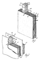
- Figure l depicts a stack 2 of positive battery plates 4 interleaved with a plurality of negative battery plates 6 and intervening microporous separator sheets 8.
- Each of the plates 4, 6 includes an integral lug l0 (only positive lugs shown) projecting therefrom and aligned with other similar plate lugs projecting from plates of like polarity.
- Each lug l0 includes a root portion l2 proximate its associated plate and a distal portion l4 more remote from the plate and serving to electrically connect its associated plate with other plates of like polarity via their respective lugs l0.
- Figures 2 and 3 illustrate one such connection (i.e., bundled and welded lugs), while Figure 7 illustrates another such connection (i.e., a plate strap cast/welded to the lugs).
- a strip of insulating material 22 is pressure-moulded directly to the roots l2 of the aligned lugs l0 as will be described in more detail hereafter.
- Figure 2 depicts cell elements 2′ and 2′′ in adjacent cell compartments of an electric storage battery and separated one from the other by an intercell partition 20.
- a positive lug set l6 of cell element 2′ is welded to a negative lug set l8 of the cell element 2′′ through an aperture in the partition 20 according to the method disclosed in US-A-4,046,062 ( Figure 5).
- the lugs l0 of each set are first bundled together adjacent the partition 20, as shown, before welding the bundles together through the aperture.
- the insulating strip 22 (which was previously moulded about the roots l2 of the lugs l0) serves as a means for controlling the bending of the lugs l0 towards the partition 20.
- the integrally-moulded strip 22 ensures that all the lugs of each set are bent in precisely the same manner and are not bent at their roots in such a manner as to contact the next adjacent plate of opposite polarity and thereby result in a short circuit between those plates.
- Beads of glue 23 may be applied to both ends of the strip 22 to securely anchor it (and hence the cell elements 2, 2′ or 2′′) to the partitions 20 for providing a significantly increased shock-resistant and vibration-resistant battery.
- Figure 3 is a side sectional view of a portion of a battery whose intracell and intercell connections are made by welding the plate lugs together through the aperture 29 substantially as depicted in Figure 2.
- the insulator strip 22′ includes tapered resilient lips 24 moulded onto each end thereof. The resilient lips 24 deflect when the plate stacks are inserted into their respective cell compartments 26 and serve not only to centre the stacks in the compartments during the assembly operation but also to tightly wedge the strip 22′ in place between partitions 28 and 30 defining the cell compartments 26 for firmly anchoring the stacks in the compartments without the need for glue or other fastening means.
- Figures 4 and 5 depict a method of assembling the plate stacks with the insulator strips of the present invention.
- the separate plates are first stacked together with their interplate separators in a conventional manner.
- the lugs l0 of each set are more precisely aligned, spaced one from the other and held in place by means of a jig 32 having comb-like jaws 33 which come together, interdigitate with the several lugs and hold them in place during the placement of a mould 34 over the tops of the lugs l0.
- the two comb-like jaws 33 reciprocate relative to each other between an open lug-release position shown in Figure 4 and a closed position for the placement of the mould 34 over the lugs.
- the lugs preferably include notches 35 on the edges thereof for receiving the pressure-moulded synthetic resin therein for better anchorage of the strip 22 to the lugs.
- the mould 34 has two comb-like portions 36 and 38 which together define a mould cavity 40 for shaping the strip 22.
- the separate fingers 37 of the mould portions 36 and 38 define slots 39 which closely receive the lugs l0 therein.
- the underside of the slots 39 are bevelled at 4l to facilitate placement of the mould 34 about the lugs l0 by guiding the tips thereof into the slots 39.
- the same polypropylene material as is used to form the battery container is preferred for simplicity and economy reasons.
- a more temperature-resistant synthetic resin e.g., polyphenylene sulfide
- thermosetting resin material will be the better choice.
- Figure 7 depicts a somewhat different use for the pressure-moulded strip of the present invention.
- a strip 44 includes upstanding flanges 46 extending along the longitudinal edges thereof. The flanges 46 and strip 44 together form a trough for receiving and shaping molten metal (e.g., lead) subsequently cast therein to form a plate strap 48 for the stack.
- molten metal e.g., lead
Landscapes
- Chemical & Material Sciences (AREA)
- Chemical Kinetics & Catalysis (AREA)
- Electrochemistry (AREA)
- General Chemical & Material Sciences (AREA)
- Engineering & Computer Science (AREA)
- Manufacturing & Machinery (AREA)
- Connection Of Batteries Or Terminals (AREA)
Abstract
A galvanic cell stack (2) includes a plurality of alternately interleaved positive (4) and negative (6) polarity plates, each including a conductive lug (l0) projecting therefrom for electrically coupling to other plates of like polarity in the cell stack (2). Each set of like polarity plate lugs (l0) includes a polymeric strip (22) pressure-moulded in situ about the roots (12) of the lugs (l0).
Description
- This invention relates to galvanic cells for electric storage batteries and more particularly to the electrochemically active cell elements therefore.
- Electric storage batteries (e.g., lead-acid batteries for motor vehicles) comprise several galvanic cells, each comprising an electrochemically active cell element immersed in electrolyte. Each cell element comprises a stack of alternating positive and negative polarity plates interleaved one with the other and separated one from the other by a thin microporous sheet known as a separator. In lead-acid batteries, these plates comprise a lead-containing material (i.e., lead dioxide, Pb0₂, for the positive plates and lead, Pb, for the negative plates) pasted onto a reticulated alloy structure called a grid. The grid supports the active material relative to the other plates in the cell element and serves to conduct electrical current throughout the plate. The grids each have a lug projecting therefrom which serves as a means to couple the plate to other plates of like polarity within the cell element and ultimately to a cell element in the adjacent cell compartment of the battery container. In some instances, the plate lugs are simply bundled and welded together through an aperture in an internal wall of the container (e.g. see Figure 5 of US-A-4,046,062). More typically, however, the plate lugs are electrically joined one to the other by a bar of lead, known as a plate strap, which is welded to, or cast about the plate lugs, such as is depicted in Figure 2 of US-A-4,046,062.
- It has heretofore been proposed to position preformed strips of insulating material over the lugs of each set of aligned positive or negative plate lugs (e.g., see US-A-2,287,802). Each preformed strip includes precut slots therein so located across the face of the strip as to register with the lugs at the time the strip is placed over the lugs. These strips have served to facilitate manufacturing (e.g., maintain alignment and spacing of the lugs), to strengthen and stabilise the stack, and to prevent accidental internal short-circuiting of the cell by keeping the plates of one polarity away from the plate strap of the opposite polarity plates as may occur, for example, where there is excessive positive plate growth in service. It has likewise been proposed to position a preformed pre-slotted trough over the plate lugs to form a mould for casting the plate strap onto the lugs during battery assembly (e.g., see US-A-3,988,l69).
- Consistently positioning a pre-slotted, preformed strip/trough over a plurality of lugs using automated assembly equipment is extremely difficult to do at commercially acceptable production rates. In this regard, it is difficult for production equipment to accurately register all the slots consistently with the various lugs and then actually to place the strip/trough over the lugs. Indeed, the slightest misalignment of even one of the lugs with respect to its corresponding slot will prevent proper placement of the strip/trough and result in an improperly assembled plate stack and ultimately a rejected battery. Accordinigly, to ensure an acceptable success rate in automatic placement of the strips/troughs onto the lug sets, the slots must be made longer and wider then the lugs with which they mate. Such oversized slots, however, result in a loose or sloppy fit of the strip/trough on the lugs which often defeats the intended purpose of the strip/trough. For example, a loose-fitting strip cannot provide precise accurate alignment or spacing of the lugs which in turn can effect subsequent manufacturing operations. Moreover, loose-fitting strips preclude the effective use thereof as a means for stabilising or strengthening the plate stack against damage during subsequent in-plant handling or in-service use of the battery. Finally, a loose-fitting trough will not provide an adequate seal for containing molten lead cast about the lugs to form a plate strap when the trough is used as a plate strap mould according to the process of US-A-3,988,l69.
- Hence, it is an object of the present invention to provide a galvanic cell element with a tightly-fitting strip of insulating material about the plate lugs. It is a further object of the present invention to provide a galvanic cell having such a strip anchored at its ends to the walls of the battery container to provide shock/vibration resistance to the cell element. It is a still further object of the present invention to provide a process for assembling battery plate stacks including pressure-moulding of a strip of insulator material in situ in and about the roots of the battery plate lugs after the plates have been interleaved one with the other. These and other objects and advantages of the present invention will become more readily apparent from the detailed description thereof which follows.
- The present invention comprehends a strip of insulating polymeric material (e.g., thermoplastic or thermosetting synthetic resin) pressure-moulded (e.g., injection-moulded) in and about the roots of previously aligned and positioned battery plate lugs so that the strip tightly engages and firmly holds the lugs in precise alignment with, and spaced from, each other. Moulding the strip in situ about the lugs eliminates the need to attempt to automatically register a pre-slotted strip with a set of aligned plate lugs after the stack has been assembled. Process-wise, the positive and negative polarity plates are first interleaved one with the other and with intervening separators in the conventional manner of assembling such battery plate stacks. Each plate has a lug projecting therefrom. Stacking of the plates is carried out so that all the positive plate lugs and negative plate lugs are aligned as separate sets along the side of the stack. A comb-like positioning jig, or similar arrangement, interdigitates with the lugs of each positive and negative set of lugs and serves to precisely align and space them one from the other. With the lugs held firmly and accurately in place by the positioning jig, a mould is positioned between and about the roots of the lugs in each positive and negative polarity set of lugs and the insulating polymeric material injected into the mould under pressure. The injected insulating material fills the mould cavity and compressively engages the roots of the lugs. After cooling, the jig and mould are removed, leaving the lugs firmly and immovably embedded within the insulating strip. The roots of the lugs will preferably have a notch formed therein to receive the moulded polymer and thereby more firmly secure the strip to the lugs. The strip thus moulded significantly strengthens and stabilises the stack against vibration or handling damage and may itself be secured to the walls of the cell compartment for firmly anchoring the cell stack in the compartment for even more resistance to damage. Finally, the strip may be moulded with upstanding flanges along the longitudinal edges thereof, which flanges, acting in concert with the strip itself, form a trough into which plate strap forming metal (e.g., lead) may be cast and shaped.
- The present invention may better be understood when considered in the light of the following detailed description of certain specific embodiments thereof which are described hereinafter with reference to the accompanying drawings, in which:
- Figure l is a perspective view of a stack of battery plates including a pressure-moulded strip made in accordance with the present invention;
- Figure 2 depicts the plate stack of Figure l joined to a similar stack in an adjacent cell compartment of a battery container;
- Figure 3 is a side-sectioned view through a battery like that depicted in Figure 2;
- Figure 4 is a perspective view depicting a mould positioned about a set of like-polarity battery plate lugs preparatory to pressure-moulding the strip of the present invention;
- Figure 5 is a side sectional view of Figure 4 taken in the direction 5-5;
- Figure 6 is a plan view of the mould and lugs shown in Figure 4, following moulding and removal of the mould; and
- Figure 7 is a perspective view of a portion of a battery plate stack depicting a trough moulded in and about the roots of the battery plate lugs.
- Figure l depicts a stack 2 of positive battery plates 4 interleaved with a plurality of negative battery plates 6 and intervening microporous separator sheets 8. Each of the plates 4, 6 includes an integral lug l0 (only positive lugs shown) projecting therefrom and aligned with other similar plate lugs projecting from plates of like polarity. Each lug l0 includes a root portion l2 proximate its associated plate and a distal portion l4 more remote from the plate and serving to electrically connect its associated plate with other plates of like polarity via their respective lugs l0. Figures 2 and 3, for example, illustrate one such connection (i.e., bundled and welded lugs), while Figure 7 illustrates another such connection (i.e., a plate strap cast/welded to the lugs). In accordance with the present invention, a strip of insulating
material 22 is pressure-moulded directly to the roots l2 of the aligned lugs l0 as will be described in more detail hereafter. - Figure 2 depicts cell elements 2′ and 2′′ in adjacent cell compartments of an electric storage battery and separated one from the other by an intercell partition 20. A positive lug set l6 of cell element 2′ is welded to a negative lug set l8 of the cell element 2′′ through an aperture in the partition 20 according to the method disclosed in US-A-4,046,062 (Figure 5). In this design, the lugs l0 of each set are first bundled together adjacent the partition 20, as shown, before welding the bundles together through the aperture. In this particular design, the insulating strip 22 (which was previously moulded about the roots l2 of the lugs l0) serves as a means for controlling the bending of the lugs l0 towards the partition 20. More particularly, the integrally-
moulded strip 22 ensures that all the lugs of each set are bent in precisely the same manner and are not bent at their roots in such a manner as to contact the next adjacent plate of opposite polarity and thereby result in a short circuit between those plates. Beads of glue 23 may be applied to both ends of thestrip 22 to securely anchor it (and hence the cell elements 2, 2′ or 2′′) to the partitions 20 for providing a significantly increased shock-resistant and vibration-resistant battery. - Figure 3 is a side sectional view of a portion of a battery whose intracell and intercell connections are made by welding the plate lugs together through the
aperture 29 substantially as depicted in Figure 2. In this embodiment, however, theinsulator strip 22′ includes taperedresilient lips 24 moulded onto each end thereof. Theresilient lips 24 deflect when the plate stacks are inserted into theirrespective cell compartments 26 and serve not only to centre the stacks in the compartments during the assembly operation but also to tightly wedge thestrip 22′ in place betweenpartitions 28 and 30 defining thecell compartments 26 for firmly anchoring the stacks in the compartments without the need for glue or other fastening means. - Figures 4 and 5 depict a method of assembling the plate stacks with the insulator strips of the present invention. In this regard, the separate plates are first stacked together with their interplate separators in a conventional manner. Thereafter, the lugs l0 of each set are more precisely aligned, spaced one from the other and held in place by means of a
jig 32 having comb-like jaws 33 which come together, interdigitate with the several lugs and hold them in place during the placement of amould 34 over the tops of the lugs l0. The two comb-like jaws 33 reciprocate relative to each other between an open lug-release position shown in Figure 4 and a closed position for the placement of themould 34 over the lugs. The lugs preferably include notches 35 on the edges thereof for receiving the pressure-moulded synthetic resin therein for better anchorage of thestrip 22 to the lugs. - The
mould 34 has two comb-like portions 36 and 38 which together define a mould cavity 40 for shaping thestrip 22. Theseparate fingers 37 of themould portions 36 and 38 defineslots 39 which closely receive the lugs l0 therein. The underside of theslots 39 are bevelled at 4l to facilitate placement of themould 34 about the lugs l0 by guiding the tips thereof into theslots 39. After themould 34 has been positioned about the roots l2 (i.e., at the notches 35 when used) of the lugs l0, liquid synthetic resin is injected into the cavity 40 (see Figure 5) through anopening 42 at one end of themould 34. Virtually any thermoplastic or thermosetting synthetic resin may be used to form thestrip 22. For Pb-acid batteries used in motor-vehicles, the same polypropylene material as is used to form the battery container is preferred for simplicity and economy reasons. However, in some applications, e.g. where thestrip 22 will be exposed to high temperatures, a more temperature-resistant synthetic resin (e.g., polyphenylene sulfide) may be used. In other situations, thermosetting resin material will be the better choice. After the resin has cooled and solidified, themould 34 is removed by separating the mould halves 36 and 38, as best shown in Figure 6. Thestrip 22 thus moulded remains in place tightly engaging the lugs l0 in what amounts to essentially a shrink fit. As a result, the lugs l0 are now firmly anchored against even minor amounts of misalignment or movement relative to one another. The relationship thus established between the lugs will remain constant throughout all further processing during manufacture of the battery and during service use of the battery. - Figure 7 depicts a somewhat different use for the pressure-moulded strip of the present invention. In this embodiment, a
strip 44 includesupstanding flanges 46 extending along the longitudinal edges thereof. Theflanges 46 andstrip 44 together form a trough for receiving and shaping molten metal (e.g., lead) subsequently cast therein to form a plate strap 48 for the stack.
Claims (5)
1. A galvanic cell including a stack (2) of positive (4) and negative (6) polarity plates alternately interleaved with one another, a conductive lug (l0) projecting from each one of said plates and being aligned with similar lugs of like polarity plates (4) along a side of said stack (2), the aligned lugs being joined electrically together in sets (l6) of like polarity, and an insulating strip (22,44) positioned around and between said aligned lugs (l0), characterised in that each lug (l0) has a root portion (l2) thereof proximate said plate and a distal portion (l4) contiguous said root portion (l2) which electrically joins said lug (l0) to adjacent aligned lugs, and said insulating strip (22,44) is a polymeric strip (22,44) pressure-moulded in-situ in and about said root portions (l2) of each set (l6) of aligned lugs (l0) so as to tightly engage said root portions (l2) of the lugs (l0) of each set (l6) and to firmly secure said aligned lugs (l0) together in fixed relationship one to the other and to insulate the set (l6) from the plates (6) of opposite polarity.
2. A galvanic cell according to claim l, characterised in that said root portion (l2) of each lug (l0) includes a notch (35) formed therein, and said strip (22) is moulded into said notch (35) so as to more firmly anchor said strip (22) to said lugs (l0).
3. A galvanic cell according to claim l, characterised in that said strip (44) includes upstanding flanges (46) extending along the longitudinal edges thereof and together therewith forms a trough containing a plate strap (48) which electrically joins the aligned lugs (l0) of said set (l6) of lugs.
4. A galvanic cell according to any one of claims l to 3, characterised in that said stack (2) is surrounded by walls (20) defining a compartment of a container of a battery containing said cell and at least one end of said strip (22) is anchored to a respective wall (20).
5. A galvanic cell according to any one of claims l to 3, characterised in that stack (2) is surrounded by walls (28,30) defining a compartment of a container of a battery containing said cell and said strip (22) includes a resilient lip (24) on each end thereof, said lips (24) being deflected into an interference fit with said walls (28,30) to firmly secure said stack (2) in said compartment.
Applications Claiming Priority (2)
| Application Number | Priority Date | Filing Date | Title |
|---|---|---|---|
| US78335985A | 1985-10-03 | 1985-10-03 | |
| US783359 | 1985-10-03 |
Publications (1)
| Publication Number | Publication Date |
|---|---|
| EP0217550A1 true EP0217550A1 (en) | 1987-04-08 |
Family
ID=25129001
Family Applications (1)
| Application Number | Title | Priority Date | Filing Date |
|---|---|---|---|
| EP86306756A Withdrawn EP0217550A1 (en) | 1985-10-03 | 1986-09-02 | Galvanic cell |
Country Status (1)
| Country | Link |
|---|---|
| EP (1) | EP0217550A1 (en) |
Cited By (2)
| Publication number | Priority date | Publication date | Assignee | Title |
|---|---|---|---|---|
| GB2245412A (en) * | 1990-06-20 | 1992-01-02 | Dowty Electronic Components | A battery |
| FR2752090A1 (en) * | 1996-08-01 | 1998-02-06 | Accumulateurs Fixes | Electrochemical generator with top of electrode plates separated by polymer stringer |
Citations (6)
| Publication number | Priority date | Publication date | Assignee | Title |
|---|---|---|---|---|
| GB817196A (en) * | 1957-04-12 | 1959-07-29 | Varley Dry Accumulators Ltd | Improvements in or relating to electric secondary batteries |
| US3396056A (en) * | 1964-06-05 | 1968-08-06 | Baroclem Sa | Electric storage batteries |
| GB1392273A (en) * | 1973-04-06 | 1975-04-30 | Yuasa Battery Co Ltd | Method of making an intercell connector type storage battery |
| US3963521A (en) * | 1969-07-17 | 1976-06-15 | Accumulatorenfabrik Sonnenschein Gmbh | Leakproof bonding of storage battery components |
| FR2308211A1 (en) * | 1975-04-16 | 1976-11-12 | Varta Batterie | ACCUMULATOR |
| US4495259A (en) * | 1983-02-11 | 1985-01-22 | The Gates Rubber Company | Vibration resistant battery |
-
1986
- 1986-09-02 EP EP86306756A patent/EP0217550A1/en not_active Withdrawn
Patent Citations (6)
| Publication number | Priority date | Publication date | Assignee | Title |
|---|---|---|---|---|
| GB817196A (en) * | 1957-04-12 | 1959-07-29 | Varley Dry Accumulators Ltd | Improvements in or relating to electric secondary batteries |
| US3396056A (en) * | 1964-06-05 | 1968-08-06 | Baroclem Sa | Electric storage batteries |
| US3963521A (en) * | 1969-07-17 | 1976-06-15 | Accumulatorenfabrik Sonnenschein Gmbh | Leakproof bonding of storage battery components |
| GB1392273A (en) * | 1973-04-06 | 1975-04-30 | Yuasa Battery Co Ltd | Method of making an intercell connector type storage battery |
| FR2308211A1 (en) * | 1975-04-16 | 1976-11-12 | Varta Batterie | ACCUMULATOR |
| US4495259A (en) * | 1983-02-11 | 1985-01-22 | The Gates Rubber Company | Vibration resistant battery |
Cited By (4)
| Publication number | Priority date | Publication date | Assignee | Title |
|---|---|---|---|---|
| GB2245412A (en) * | 1990-06-20 | 1992-01-02 | Dowty Electronic Components | A battery |
| US5230967A (en) * | 1990-06-20 | 1993-07-27 | Paul Radmall | Battery comprising interconnecting means of electrochemical cell units |
| GB2245412B (en) * | 1990-06-20 | 1995-01-25 | Dowty Electronic Components | Battery comprising interconnecting means of electrochemical cell units |
| FR2752090A1 (en) * | 1996-08-01 | 1998-02-06 | Accumulateurs Fixes | Electrochemical generator with top of electrode plates separated by polymer stringer |
Similar Documents
| Publication | Publication Date | Title |
|---|---|---|
| EP0244943B1 (en) | Electric storage battery | |
| US4800142A (en) | Electric storage battery | |
| US5256502A (en) | Modular, multicell lead-acid batteries | |
| EP0589549B1 (en) | Lead acid batteries containing center lug plates and high performance cast-on straps | |
| EP2913868A1 (en) | Secondary battery and method of manufacturing the same | |
| EP4220795A2 (en) | Cylindrical secondary battery | |
| US4209575A (en) | Multi-cell batteries | |
| US4764182A (en) | Electric storage battery | |
| KR20040092531A (en) | Electrode assembly of secondary battery | |
| US4376156A (en) | Battery intercell connector manifold | |
| CN120497595A (en) | Battery belt | |
| EP0217550A1 (en) | Galvanic cell | |
| US4675991A (en) | Method of assembling electric storage batteries | |
| US4423123A (en) | Electric storage battery and a method of making the same | |
| US3753783A (en) | Battery, components, and method of making | |
| JPH0982306A (en) | Lead acid battery and manufacturing method thereof | |
| US4233373A (en) | Cell casing and grommet therefore | |
| US4173326A (en) | Cast on mold inserts | |
| US5731103A (en) | Method and apparatus for positioning a battery terminal strap | |
| DE102021210275B4 (en) | Process for producing a battery | |
| EP0251970B1 (en) | An electric storage battery | |
| EP3595045B1 (en) | Secondary battery | |
| JPH01163962A (en) | Sealed lead-acid battery | |
| JPH0412609Y2 (en) | ||
| GB2160700A (en) | Multi-tubular battery plates |
Legal Events
| Date | Code | Title | Description |
|---|---|---|---|
| PUAI | Public reference made under article 153(3) epc to a published international application that has entered the european phase |
Free format text: ORIGINAL CODE: 0009012 |
|
| 17P | Request for examination filed |
Effective date: 19860909 |
|
| AK | Designated contracting states |
Kind code of ref document: A1 Designated state(s): DE FR GB |
|
| STAA | Information on the status of an ep patent application or granted ep patent |
Free format text: STATUS: THE APPLICATION HAS BEEN WITHDRAWN |
|
| 18W | Application withdrawn |
Withdrawal date: 19870512 |
|
| RIN1 | Information on inventor provided before grant (corrected) |
Inventor name: MCCARTNEY, CHARLES P. Inventor name: BISH, JAMES R. |