EP0217170B1 - Worm reduction gear with connections - Google Patents
Worm reduction gear with connections Download PDFInfo
- Publication number
- EP0217170B1 EP0217170B1 EP86112259A EP86112259A EP0217170B1 EP 0217170 B1 EP0217170 B1 EP 0217170B1 EP 86112259 A EP86112259 A EP 86112259A EP 86112259 A EP86112259 A EP 86112259A EP 0217170 B1 EP0217170 B1 EP 0217170B1
- Authority
- EP
- European Patent Office
- Prior art keywords
- worm
- reduction gear
- casing
- tube
- shaft
- Prior art date
- Legal status (The legal status is an assumption and is not a legal conclusion. Google has not performed a legal analysis and makes no representation as to the accuracy of the status listed.)
- Expired - Lifetime
Links
- 238000004804 winding Methods 0.000 claims description 2
- 125000006850 spacer group Chemical group 0.000 abstract description 5
- 238000004519 manufacturing process Methods 0.000 description 6
- 239000000463 material Substances 0.000 description 4
- 238000010276 construction Methods 0.000 description 2
- 238000007789 sealing Methods 0.000 description 2
- 230000006978 adaptation Effects 0.000 description 1
- 210000003608 fece Anatomy 0.000 description 1
- 238000009434 installation Methods 0.000 description 1
- 239000010871 livestock manure Substances 0.000 description 1
- 239000000725 suspension Substances 0.000 description 1
Images


Classifications
-
- F—MECHANICAL ENGINEERING; LIGHTING; HEATING; WEAPONS; BLASTING
- F16—ENGINEERING ELEMENTS AND UNITS; GENERAL MEASURES FOR PRODUCING AND MAINTAINING EFFECTIVE FUNCTIONING OF MACHINES OR INSTALLATIONS; THERMAL INSULATION IN GENERAL
- F16H—GEARING
- F16H57/00—General details of gearing
- F16H57/02—Gearboxes; Mounting gearing therein
- F16H57/039—Gearboxes for accommodating worm gears
-
- F—MECHANICAL ENGINEERING; LIGHTING; HEATING; WEAPONS; BLASTING
- F16—ENGINEERING ELEMENTS AND UNITS; GENERAL MEASURES FOR PRODUCING AND MAINTAINING EFFECTIVE FUNCTIONING OF MACHINES OR INSTALLATIONS; THERMAL INSULATION IN GENERAL
- F16H—GEARING
- F16H1/00—Toothed gearings for conveying rotary motion
- F16H1/02—Toothed gearings for conveying rotary motion without gears having orbital motion
- F16H1/04—Toothed gearings for conveying rotary motion without gears having orbital motion involving only two intermeshing members
- F16H1/12—Toothed gearings for conveying rotary motion without gears having orbital motion involving only two intermeshing members with non-parallel axes
- F16H1/16—Toothed gearings for conveying rotary motion without gears having orbital motion involving only two intermeshing members with non-parallel axes comprising worm and worm-wheel
-
- F—MECHANICAL ENGINEERING; LIGHTING; HEATING; WEAPONS; BLASTING
- F16—ENGINEERING ELEMENTS AND UNITS; GENERAL MEASURES FOR PRODUCING AND MAINTAINING EFFECTIVE FUNCTIONING OF MACHINES OR INSTALLATIONS; THERMAL INSULATION IN GENERAL
- F16H—GEARING
- F16H57/00—General details of gearing
- F16H57/02—Gearboxes; Mounting gearing therein
- F16H2057/02034—Gearboxes combined or connected with electric machines
-
- F—MECHANICAL ENGINEERING; LIGHTING; HEATING; WEAPONS; BLASTING
- F16—ENGINEERING ELEMENTS AND UNITS; GENERAL MEASURES FOR PRODUCING AND MAINTAINING EFFECTIVE FUNCTIONING OF MACHINES OR INSTALLATIONS; THERMAL INSULATION IN GENERAL
- F16H—GEARING
- F16H57/00—General details of gearing
- F16H57/02—Gearboxes; Mounting gearing therein
- F16H2057/02039—Gearboxes for particular applications
- F16H2057/02069—Gearboxes for particular applications for industrial applications
- F16H2057/02073—Reduction gearboxes for industry
-
- Y—GENERAL TAGGING OF NEW TECHNOLOGICAL DEVELOPMENTS; GENERAL TAGGING OF CROSS-SECTIONAL TECHNOLOGIES SPANNING OVER SEVERAL SECTIONS OF THE IPC; TECHNICAL SUBJECTS COVERED BY FORMER USPC CROSS-REFERENCE ART COLLECTIONS [XRACs] AND DIGESTS
- Y10—TECHNICAL SUBJECTS COVERED BY FORMER USPC
- Y10S—TECHNICAL SUBJECTS COVERED BY FORMER USPC CROSS-REFERENCE ART COLLECTIONS [XRACs] AND DIGESTS
- Y10S384/00—Bearings
- Y10S384/90—Cooling or heating
- Y10S384/903—Retaining ring
-
- Y—GENERAL TAGGING OF NEW TECHNOLOGICAL DEVELOPMENTS; GENERAL TAGGING OF CROSS-SECTIONAL TECHNOLOGIES SPANNING OVER SEVERAL SECTIONS OF THE IPC; TECHNICAL SUBJECTS COVERED BY FORMER USPC CROSS-REFERENCE ART COLLECTIONS [XRACs] AND DIGESTS
- Y10—TECHNICAL SUBJECTS COVERED BY FORMER USPC
- Y10T—TECHNICAL SUBJECTS COVERED BY FORMER US CLASSIFICATION
- Y10T74/00—Machine element or mechanism
- Y10T74/19—Gearing
- Y10T74/19642—Directly cooperating gears
- Y10T74/19698—Spiral
- Y10T74/19828—Worm
-
- Y—GENERAL TAGGING OF NEW TECHNOLOGICAL DEVELOPMENTS; GENERAL TAGGING OF CROSS-SECTIONAL TECHNOLOGIES SPANNING OVER SEVERAL SECTIONS OF THE IPC; TECHNICAL SUBJECTS COVERED BY FORMER USPC CROSS-REFERENCE ART COLLECTIONS [XRACs] AND DIGESTS
- Y10—TECHNICAL SUBJECTS COVERED BY FORMER USPC
- Y10T—TECHNICAL SUBJECTS COVERED BY FORMER US CLASSIFICATION
- Y10T74/00—Machine element or mechanism
- Y10T74/21—Elements
- Y10T74/2186—Gear casings
Definitions
- the invention relates to a worm reduction gear having a casing and an embedded and driven worm which adheres snugly to a worm wheel embedded on a worm wheel shaft; said worm wheel is inserted in the worm between bearings; the bearings are seated in centering bushes extending to one seal each, inserted in the casing.
- the engineering problem to be solved by the invention is a multiple one: to simplify the product, to make it easy to manufacture, to make it widely applicable, and to make it cheaper, especially in terms of materials and energy. It is the object of the invention to achieve a pure structure capable of enduring higher loads on a lesser weight of the reducing gear, on less material used and on less space.
- the worm reducing gear is to be designed so that manual work will no more be necessary, that it will be manufactured by machine, preferably automatic, in mass production.
- a reducing gear according to the invention should have only the parts which are absolutely necessary, these being as simple as possible, and the structure should be stronger, i.e. strong enough to make it possible to build in, in the same casing, weaker or stronger driving components like a worm, worm-wheel, a shaft, bearings, etc., in order to make the product less expensive.
- the reducing gear should be capable of bearing driven structures and of steering, by turning in the center of the driving shaft, the wheels which should be fastened on the shaft either both on the same side of the shaft or one on each side of the shaft. These wheels should turn about the vertical and the horizontal axes.
- the control of the reduction gear on a mobile machine may be designed in three ways: with another reduction gear, with a cogwheel and a toothed rack, or manually with a lever.
- Worm reduction gears are made of a standard box-like casing to which a cover is screwed on either side in which a bearing and a seal are placed and which extend in a base in which two bores are cut through the fastening the worm reduction gear. On its ends the worm reduction gear has covers screwed to the casing.
- a worm reduction gear is disclosed in US-A-4 261 218.
- worm reduction gears are not suitable for the manufacture on automatic machines and by robots-as a result, they are too expensive and not available enough. They are not suitable for simultaneous bearing and driving of the same loads. Sealing and centering are imperfect and unreliable.
- the existing reduction gear types are complicated to assemble; the worm and the worm wheel are not always fixed within the tolerances required because the assembly depends more or less on the human factor-the mechanic who has to hold the sides of the worm reducing gear casing in his hands while trying to adjust them with gaskets and bolts during his assembly work.
- worm reduction gears do not allow optignal installation, suspension, carrying, and driving of the same loads, they do not allow optional location and adaptation to suit any user. For the same connect load and actual load, the existing worm reduction gears are much larger and heavier. In addition, in case of known, well established worm reduction gears a great variety of gears are to be made, varying in volume, weight and power.
- the worm reducing gear of the invention is intended to eliminate the need for manual work, and can be manufactured by machine, preferably automatically, in mass production.
- the reducing gear should be capable of bearing driven structures and of steering, by turning in the center of the driving shaft, the wheels which should be fastened on the shaft either both on the same side of the shaft or one on each side of the shaft. These wheels should turn about the vertical and the horizontal axes.
- the control of the reduction gear on a mobile machine may be supplied by another reduction gear, by a cogwheel and a toothed rack, or manually by a lever.
- a worm reduction gear according to the invention is characterized in that the casing is formed by a first cylindrical tube and a second cylindrical tube having an axis perpendicular to the axis of the first cylindrical tube, that the worm wheel shaft extends along the axis of the first tube, the seals being rings situated on the inner cylindrical mantle of the cylindrical tube at a distance from the lateral side of the latter and that retaining rings for holding said centering bushes are situated in grooves in said tube.
- the worm reduction gear according to this invention is designed that it does not need any bolts or screws.
- the product can be manufactured completely by machine, preferably on a lathe.
- the reduction gear consists of less components, the remaining ones being incomparably simpler, cheaper, and more reliable.
- a reduction gear can be made by machine, completely automatically, in mass production.
- sealing is cheaper, simpler, and more reliable, it does not depend on the quality of the surfaces and on the accuracy of placing the gaskets as much as it did before.
- the reduction gear can be applied provided that the gear is borne directly by the electromotor standing on its standard legs.
- flat lateral gaskets are to be replaced by round flange gaskets.
- the reduction gear is equipped for bearing and driving a machine and for steering, by turning in the centre of the driving shaft, the wheels which should be fastened on the shaft either both on the same side of the shaft or one on each side of it. These wheels turn about the vertical and horizontal axes.
- the control of the reduction gear on a mobile machine may be designed in three ways: with another reduction gear, with a cogwheel and a toothed rack, or manually with a lever.
- a worm reduction gear according to the invention is suitable for a variety of applications.
- the reduction gear has several connections and supports for bearing attached driving structures and loads at the same time; in case of a fork-lift, this is a connection for a workshop lift and for a construction trade bracket lift, further a connection for vineyard and garden ploughing, for transporting manure to a vineyard; a reduction gear designed for conveyor worms and transporters in the processing industry and construction industry. All the needs have been met by worm reduction gears in three casing sizes only.
- a worm reduction gear according to this invention has a casing 1 and consists of a tube 2 and a tube 3, a flange 4 welded together from three pieces or cast from one piece, including supporting connections 5 for a steering wheel 6, a connection 8 for a hoist 9, and a connection 10 for, e.g., a worm conveyer 11.
- the other end of the worm 29 is fixed in an axial bearing 34 located between the seating 35 and the Seeger ring 36 and fastened by two bearing nuts 37, all covered by a cover 38 and sealed by a round gasket 39 limited by a seating 40 and a Seeger ring 41.
- the cover incorporates a bolt 42 with a point where the reduction gear is filled with oil.
- the bolt 42 also serves as cover remover.
- the casing 43 incorporates the bearings 44 and 45 which are fixed through a spacer 46 on which another casing 1 is located designed for left and right steering of a vehicle or a machine standing on wheels 47 and 48.
- a worm reduction gear When a worm reduction gear is suspended on a guiding and supporting section 49 it has two supports with plugs and bearings 50 and, in addition if necessary, another support 51 with a bearing 52 which are fastened by two spacing screws 53 between which on the shaft 13 a winding drum 54 with a string is located.
- the reduction gear can also be designed for other applications like the already shown worm conveyer with worm reduction gear 11-a casing 55, fastened to a flange 10 by a bolt, with a labyrinth flange 56 and a labyrinth cover 57 in which there is a bearing 58 supporting a worm 59 with counter-labyrinth 60, while the other leg of the labyrinth hub 61 is fixed on a shaft 14 by a peg 62, between which there is, preferably, a tubular shaft 63.
- the worm conveyer has an inlet opening 64 and an outlet opening 65.
- a worm reduction gear according to the invention with connections works as follows:
- An electromotor 32 drives preferably through a peg 31 and carries a worm 29 which is guided and axially held in position by a bearing 34 and which is tightly enclosed by a worm wheel 25 which drives a shaft 12 through pegs 28, and when two wheels 47 and a supporting base 5 are fastened to the shaft and when another worm reduction gear for left and right turning is applied here, then the worm reduction gear carries, steers, and drives the machine simultaneously.
- a worm reduction gear used as a hoist however, carries and drives the load. And further, a worm reduction gear can be applied only as the driving part of a machine.
Landscapes
- Engineering & Computer Science (AREA)
- General Engineering & Computer Science (AREA)
- Mechanical Engineering (AREA)
- Gear Transmission (AREA)
- General Details Of Gearings (AREA)
- Power Steering Mechanism (AREA)
- Dry Shavers And Clippers (AREA)
Abstract
Description
- The invention relates to a worm reduction gear having a casing and an embedded and driven worm which adheres snugly to a worm wheel embedded on a worm wheel shaft; said worm wheel is inserted in the worm between bearings; the bearings are seated in centering bushes extending to one seal each, inserted in the casing.
- The engineering problem to be solved by the invention is a multiple one: to simplify the product, to make it easy to manufacture, to make it widely applicable, and to make it cheaper, especially in terms of materials and energy. It is the object of the invention to achieve a pure structure capable of enduring higher loads on a lesser weight of the reducing gear, on less material used and on less space. The worm reducing gear is to be designed so that manual work will no more be necessary, that it will be manufactured by machine, preferably automatic, in mass production. A reducing gear according to the invention should have only the parts which are absolutely necessary, these being as simple as possible, and the structure should be stronger, i.e. strong enough to make it possible to build in, in the same casing, weaker or stronger driving components like a worm, worm-wheel, a shaft, bearings, etc., in order to make the product less expensive.
- In addition to its driving ability, the reducing gear should be capable of bearing driven structures and of steering, by turning in the center of the driving shaft, the wheels which should be fastened on the shaft either both on the same side of the shaft or one on each side of the shaft. These wheels should turn about the vertical and the horizontal axes. The control of the reduction gear on a mobile machine may be designed in three ways: with another reduction gear, with a cogwheel and a toothed rack, or manually with a lever.
- The state of the art has long been almost unchanged. Worm reduction gears are made of a standard box-like casing to which a cover is screwed on either side in which a bearing and a seal are placed and which extend in a base in which two bores are cut through the fastening the worm reduction gear. On its ends the worm reduction gear has covers screwed to the casing. Such a worm reduction gear is disclosed in US-A-4 261 218.
- As they are, worm reduction gears are not suitable for the manufacture on automatic machines and by robots-as a result, they are too expensive and not available enough. They are not suitable for simultaneous bearing and driving of the same loads. Sealing and centering are imperfect and unreliable. The existing reduction gear types are complicated to assemble; the worm and the worm wheel are not always fixed within the tolerances required because the assembly depends more or less on the human factor-the mechanic who has to hold the sides of the worm reducing gear casing in his hands while trying to adjust them with gaskets and bolts during his assembly work.
- As they are, worm reduction gears do not allow optignal installation, suspension, carrying, and driving of the same loads, they do not allow optional location and adaptation to suit any user. For the same connect load and actual load, the existing worm reduction gears are much larger and heavier. In addition, in case of known, well established worm reduction gears a great variety of gears are to be made, varying in volume, weight and power.
- It is the object of the invention to simplify a worm reduction gear, to make it easy to manufacture, to make it widely applicable, and to make it less costly, especially in terms of materials and energy.
- It is another object of the invention to achieve a structure capable of enduring higher loads with a reducing gear of less weight, using less material and occupying less space.
- The worm reducing gear of the invention is intended to eliminate the need for manual work, and can be manufactured by machine, preferably automatically, in mass production.
- It is another object of the invention to provide a reducing gear which has only the parts which are absolutely necessary, these being as simple as possible, and a structure which is stronger, i.e. strong enough to make it possible to build in, in the same casing, weaker or stronger driving components via a worm, worm-wheel, a shaft, bearings, etc., in order to make the product less expensive.
- Advantageously the reducing gear should be capable of bearing driven structures and of steering, by turning in the center of the driving shaft, the wheels which should be fastened on the shaft either both on the same side of the shaft or one on each side of the shaft. These wheels should turn about the vertical and the horizontal axes. The control of the reduction gear on a mobile machine may be supplied by another reduction gear, by a cogwheel and a toothed rack, or manually by a lever.
- A worm reduction gear according to the invention is characterized in that the casing is formed by a first cylindrical tube and a second cylindrical tube having an axis perpendicular to the axis of the first cylindrical tube, that the worm wheel shaft extends along the axis of the first tube, the seals being rings situated on the inner cylindrical mantle of the cylindrical tube at a distance from the lateral side of the latter and that retaining rings for holding said centering bushes are situated in grooves in said tube.
- The worm reduction gear according to this invention is designed that it does not need any bolts or screws. Thus, the product can be manufactured completely by machine, preferably on a lathe. The reduction gear consists of less components, the remaining ones being incomparably simpler, cheaper, and more reliable. Now, a reduction gear can be made by machine, completely automatically, in mass production.
- In addition, sealing is cheaper, simpler, and more reliable, it does not depend on the quality of the surfaces and on the accuracy of placing the gaskets as much as it did before. On an electromotor, the reduction gear can be applied provided that the gear is borne directly by the electromotor standing on its standard legs. According to the invention, flat lateral gaskets are to be replaced by round flange gaskets.
- Further, the reduction gear is equipped for bearing and driving a machine and for steering, by turning in the centre of the driving shaft, the wheels which should be fastened on the shaft either both on the same side of the shaft or one on each side of it. These wheels turn about the vertical and horizontal axes. The control of the reduction gear on a mobile machine may be designed in three ways: with another reduction gear, with a cogwheel and a toothed rack, or manually with a lever.
- A worm reduction gear according to the invention is suitable for a variety of applications. For this purpose, the reduction gear has several connections and supports for bearing attached driving structures and loads at the same time; in case of a fork-lift, this is a connection for a workshop lift and for a construction trade bracket lift, further a connection for vineyard and garden ploughing, for transporting manure to a vineyard; a reduction gear designed for conveyor worms and transporters in the processing industry and construction industry. All the needs have been met by worm reduction gears in three casing sizes only.
- In details, the invention is shown on the following drawings:
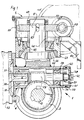
- Fig. 1 is an elevational view of a worm reduction gear according to the invention, with a connection for a steering wheel;
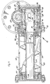
- Fig. 2 is a side-elevational view of a worm reduction gear according to the invention;
- Fig. 3 is an elevational view of a worm reduction gear according to the invention, with a mobile hoist fixed to it;
- Fig. 4 is a side-elevational view of a worm reduction gear according to the invention, with a mobile hoist fixed to it;
- Fig. 5 is a cross-sectional view of a worm reduction gear according to the invention, applied in a worm-conveyer.
- A worm reduction gear according to this invention has a
casing 1 and consists of atube 2 and atube 3, a flange 4 welded together from three pieces or cast from one piece, including supportingconnections 5 for asteering wheel 6, a connection 8 for ahoist 9, and aconnection 10 for, e.g., aworm conveyer 11. - Inserted in the
casing 1 is ashaft bearings centering cover 18 withround flange gaskets seals 21 and 22 which are limited and fixed by two Seegerrings bearings worm wheel 25 withspacers peg 28, while theworm wheel 25 fits snugly against theworm 29 which is inserted in thetube 3 and fixed on theshaft 30 by apeg 31 of anelectromotor 32 and sealed by aseal 33. - The other end of the
worm 29 is fixed in an axial bearing 34 located between theseating 35 and the Seeger ring 36 and fastened by twobearing nuts 37, all covered by acover 38 and sealed by around gasket 39 limited by a seating 40 and a Seegerring 41. The cover incorporates abolt 42 with a point where the reduction gear is filled with oil. Thebolt 42 also serves as cover remover. - If and when the supporting
connection 5 for thesteering wheel 6 is placed on thetube 3 thecasing 43 incorporates thebearings spacer 46 on which anothercasing 1 is located designed for left and right steering of a vehicle or a machine standing onwheels - Between the
second casing 1 and thesteering wheel 6 there is anassembly console 66 supporting (onbearings casing 1 and thesteering wheel 6. Between thebearing 45 and the worm wheel 25-which is on the supportingconnection 5 with a wedge 67-there is aspacer 46 fixed with two bearingnuts 69. - When a worm reduction gear is suspended on a guiding and supporting
section 49 it has two supports with plugs andbearings 50 and, in addition if necessary, anothersupport 51 with abearing 52 which are fastened by twospacing screws 53 between which on the shaft 13 awinding drum 54 with a string is located. Further, the reduction gear can also be designed for other applications like the already shown worm conveyer with worm reduction gear 11-acasing 55, fastened to aflange 10 by a bolt, with alabyrinth flange 56 and alabyrinth cover 57 in which there is abearing 58 supporting aworm 59 withcounter-labyrinth 60, while the other leg of thelabyrinth hub 61 is fixed on ashaft 14 by apeg 62, between which there is, preferably, atubular shaft 63. The worm conveyer has an inlet opening 64 and an outlet opening 65. - A worm reduction gear according to the invention with connections works as follows:
- An
electromotor 32 drives preferably through apeg 31 and carries aworm 29 which is guided and axially held in position by abearing 34 and which is tightly enclosed by aworm wheel 25 which drives ashaft 12 throughpegs 28, and when twowheels 47 and a supportingbase 5 are fastened to the shaft and when another worm reduction gear for left and right turning is applied here, then the worm reduction gear carries, steers, and drives the machine simultaneously. A worm reduction gear used as a hoist, however, carries and drives the load. And further, a worm reduction gear can be applied only as the driving part of a machine.
Claims (7)
Priority Applications (1)
| Application Number | Priority Date | Filing Date | Title |
|---|---|---|---|
| AT86112259T ATE50334T1 (en) | 1985-09-10 | 1986-09-04 | WORM GEAR WITH CONNECTORS. |
Applications Claiming Priority (2)
| Application Number | Priority Date | Filing Date | Title |
|---|---|---|---|
| YU1418/85 | 1985-09-10 | ||
| YU01418/85A YU141885A (en) | 1985-09-10 | 1985-09-10 | Worm gear reductor with connections |
Publications (2)
| Publication Number | Publication Date |
|---|---|
| EP0217170A1 EP0217170A1 (en) | 1987-04-08 |
| EP0217170B1 true EP0217170B1 (en) | 1990-02-07 |
Family
ID=25554097
Family Applications (1)
| Application Number | Title | Priority Date | Filing Date |
|---|---|---|---|
| EP86112259A Expired - Lifetime EP0217170B1 (en) | 1985-09-10 | 1986-09-04 | Worm reduction gear with connections |
Country Status (6)
| Country | Link |
|---|---|
| US (2) | US4774848A (en) |
| EP (1) | EP0217170B1 (en) |
| AT (1) | ATE50334T1 (en) |
| CA (1) | CA1280913C (en) |
| DE (1) | DE3668969D1 (en) |
| YU (1) | YU141885A (en) |
Families Citing this family (15)
| Publication number | Priority date | Publication date | Assignee | Title |
|---|---|---|---|---|
| DE3733922A1 (en) * | 1987-10-07 | 1989-04-20 | Brose Fahrzeugteile | ELECTRIC VARIABLE MOTOR WITH GEARBOX IN A MOTOR VEHICLE |
| US4951884A (en) * | 1989-04-28 | 1990-08-28 | Koenig Larry E | Power auger machine with bearing shield |
| JP2880782B2 (en) * | 1990-09-17 | 1999-04-12 | 株式会社東京自働機械製作所 | Screw feeder |
| AT413054B (en) * | 1992-05-04 | 2005-10-15 | Joerg Helmut | GETRIEBEGEHÄUSE |
| DE9413344U1 (en) * | 1994-08-18 | 1995-12-14 | Getriebebau-Nord Schlicht + Küchenmeister GmbH & Co, 22941 Bargteheide | transmission |
| US7293362B2 (en) * | 2003-10-20 | 2007-11-13 | Ideal Industries, Inc. | Drill powered cable cutter |
| CN100478214C (en) * | 2005-04-28 | 2009-04-15 | C.劳勃汉默斯坦两合有限公司 | Actuator for a motor vehicle seat |
| DE102005046354A1 (en) * | 2005-09-28 | 2007-03-29 | Robert Bosch Gmbh | Transmission drive unit for use in e.g. motor vehicle, has drive component with axial stopper that lies at axial bearing surface of bearing bracket, which is pressed against axial stopper by material deformation of support pipe |
| DE102006062240B4 (en) * | 2006-12-22 | 2008-09-04 | PFAFF AQS GmbH automatische Qualitätskontrollsysteme | Detachable coupling |
| US7562879B1 (en) | 2008-04-30 | 2009-07-21 | Cnh America Llc | Method and apparatus for creating an auger arm and bearing seal |
| CN103527727B (en) * | 2013-10-23 | 2016-01-06 | 厦门市文忠不锈钢制品有限公司 | Speed-change gear box |
| USD749657S1 (en) * | 2014-11-19 | 2016-02-16 | American Axle & Manufacturing, Inc. | Gerotor housing |
| USD753743S1 (en) * | 2015-03-17 | 2016-04-12 | Nabtesco Corporation | Reduction gear |
| USD753744S1 (en) * | 2015-03-17 | 2016-04-12 | Nabtesco Corporation | Reduction gear |
| DE102015105527A1 (en) * | 2015-04-10 | 2016-10-13 | Cavex GmbH & Co. KG | Gear housing for a worm gear |
Family Cites Families (19)
| Publication number | Priority date | Publication date | Assignee | Title |
|---|---|---|---|---|
| GB190707054A (en) * | 1907-03-23 | 1907-10-17 | Francis Edwin Brown | An Improved Worm Drive for Mechanically Propelled Vehicles and for other Purposes. |
| US1737228A (en) * | 1927-08-25 | 1929-11-26 | Irwin Foundry And Mine Car Com | Industrial car wheel |
| US1843875A (en) * | 1928-12-03 | 1932-02-02 | Alliance Machine Co | Worm drive |
| US2108262A (en) * | 1933-11-03 | 1938-02-15 | Dain Mfg Company | Worm and worm gear assembly |
| US2225957A (en) * | 1938-08-26 | 1940-12-24 | Merkle Korff Gear Company | Reduction drive |
| US2288849A (en) * | 1940-01-12 | 1942-07-07 | Schwitzer Cummins Company | Power drive for stokers |
| US2272454A (en) * | 1940-06-11 | 1942-02-10 | Wilfley & Sons Inc A | Seal for centrifugal pumps |
| US2351060A (en) * | 1940-11-12 | 1944-06-13 | Martin B Mclauthlin | Hoisting machine |
| US2509526A (en) * | 1947-01-27 | 1950-05-30 | Fmc Corp | Transmission arrangement for closely spaced wheels |
| US2763471A (en) * | 1952-12-18 | 1956-09-18 | W M Cissell Mfg Co Inc | Driving mechanism |
| FR1276068A (en) * | 1960-10-04 | 1961-11-17 | Improvements to worm gearboxes | |
| AT271123B (en) * | 1967-06-15 | 1969-05-27 | Helmut Joerg | Gear housing |
| FR2292156A1 (en) * | 1974-11-21 | 1976-06-18 | Irrico Cie Equip Pour Irrigati | CLUTCHABLE REDUCING GEAR |
| DE2612462A1 (en) * | 1976-03-24 | 1977-10-06 | Bosch Gmbh Robert | DRIVE UNIT FOR ADJUSTING AN ELEMENT BETWEEN TWO END POSITIONS |
| US4261218A (en) * | 1978-12-26 | 1981-04-14 | Eagan Joseph A Sen | Speed reducer adjustment means |
| JPS5697082A (en) * | 1979-12-27 | 1981-08-05 | Brose Verwaltung | Electrical driving device |
| SE8205963L (en) * | 1982-10-20 | 1984-04-21 | Skf Nova Ab | KRAFTOVERFORINGSANORDNING |
| JPS61211558A (en) * | 1985-03-15 | 1986-09-19 | Shin Meiwa Ind Co Ltd | Reduction gear employing worm gear |
| FR2580759B1 (en) * | 1985-04-18 | 1990-02-23 | Marchal Equip Auto | DEVICE FOR CONTROLLING THE MOVEMENT OF AN ELEMENT, PARTICULARLY A SEAT OR PARTS OF A SEAT OF A MOTOR VEHICLE, RELATIVE TO A CONSTRUCTION |
-
1985
- 1985-09-10 YU YU01418/85A patent/YU141885A/en unknown
-
1986
- 1986-09-04 EP EP86112259A patent/EP0217170B1/en not_active Expired - Lifetime
- 1986-09-04 DE DE8686112259T patent/DE3668969D1/en not_active Expired - Lifetime
- 1986-09-04 AT AT86112259T patent/ATE50334T1/en not_active IP Right Cessation
- 1986-09-08 US US06/905,273 patent/US4774848A/en not_active Expired - Fee Related
- 1986-09-09 CA CA000517833A patent/CA1280913C/en not_active Expired - Lifetime
-
1988
- 1988-09-23 US US07/249,424 patent/US4947699A/en not_active Expired - Fee Related
Also Published As
| Publication number | Publication date |
|---|---|
| US4947699A (en) | 1990-08-14 |
| US4774848A (en) | 1988-10-04 |
| EP0217170A1 (en) | 1987-04-08 |
| YU141885A (en) | 1988-10-31 |
| ATE50334T1 (en) | 1990-02-15 |
| CA1280913C (en) | 1991-03-05 |
| DE3668969D1 (en) | 1990-03-15 |
Similar Documents
| Publication | Publication Date | Title |
|---|---|---|
| EP0217170A1 (en) | Worm reduction gear with connections | |
| US5201638A (en) | Hydraulic energy supply cart | |
| CA2127131C (en) | Arrangement for the rotary actuation of a machine and plant part with worm gear | |
| US5094542A (en) | Modular mixer system | |
| IT8422956V0 (en) | QUICK LOCKING NUT FOR THE LOCKING OF MOTOR VEHICLE WHEELS, PARTICULARLY ON THE LOCKING FLANGE OF A BALANCING MACHINE. | |
| FI88275C (en) | HJULNAVSKONSTRUKTION | |
| JPS626958B2 (en) | ||
| US4177610A (en) | Apparatus for machining large heavy workpieces in situs | |
| EP0239574B1 (en) | Differential drive assembly with two inputs | |
| US2906137A (en) | Speed reducer | |
| US2624445A (en) | Unitary power-driven roller conveyer | |
| KR930001092B1 (en) | Power Drive Screw Cutting Machine and Its Base | |
| US3690398A (en) | Hydrostatic drive | |
| US3954120A (en) | Gear box | |
| EP0202525A1 (en) | Lift driving gear and mounting method | |
| NL9200256A (en) | BEARING CHAIR FOR WIND ENERGY INSTALLATIONS. | |
| US6622853B2 (en) | Pivoting mounting block for motorized conveyor pulleys | |
| EP0386809A1 (en) | Conveyor | |
| KR0128726B1 (en) | A jig for heavy weight materials to disassemble or assemble | |
| JPS62150001A (en) | Scroll type fluid machine | |
| SE1950959A1 (en) | A drive arrangement for a floor surfacing machine and a floor surfacing machine | |
| US5992730A (en) | Method for assembling a trolley for an overhead traveling crane | |
| FI72453B (en) | ANORDINATION FOR SPEAKING BEARBETNING AV TRAE MED EN CYLINDERSAOG. | |
| KR940008329Y1 (en) | Device for adhering wheel of travel drive for over head travelling crane | |
| CN217076063U (en) | Automatic conveying and overturning device for axle |
Legal Events
| Date | Code | Title | Description |
|---|---|---|---|
| PUAI | Public reference made under article 153(3) epc to a published international application that has entered the european phase |
Free format text: ORIGINAL CODE: 0009012 |
|
| AK | Designated contracting states |
Kind code of ref document: A1 Designated state(s): AT BE CH DE FR GB IT LI NL SE |
|
| 17P | Request for examination filed |
Effective date: 19871002 |
|
| 17Q | First examination report despatched |
Effective date: 19880829 |
|
| GRAA | (expected) grant |
Free format text: ORIGINAL CODE: 0009210 |
|
| AK | Designated contracting states |
Kind code of ref document: B1 Designated state(s): AT BE CH DE FR GB IT LI NL SE |
|
| PG25 | Lapsed in a contracting state [announced via postgrant information from national office to epo] |
Ref country code: SE Effective date: 19900207 Ref country code: NL Effective date: 19900207 Ref country code: LI Effective date: 19900207 Ref country code: CH Effective date: 19900207 Ref country code: BE Effective date: 19900207 |
|
| REF | Corresponds to: |
Ref document number: 50334 Country of ref document: AT Date of ref document: 19900215 Kind code of ref document: T |
|
| REF | Corresponds to: |
Ref document number: 3668969 Country of ref document: DE Date of ref document: 19900315 |
|
| ITF | It: translation for a ep patent filed | ||
| REG | Reference to a national code |
Ref country code: CH Ref legal event code: PL |
|
| ET | Fr: translation filed | ||
| NLV1 | Nl: lapsed or annulled due to failure to fulfill the requirements of art. 29p and 29m of the patents act | ||
| PG25 | Lapsed in a contracting state [announced via postgrant information from national office to epo] |
Ref country code: GB Effective date: 19900904 |
|
| PLBE | No opposition filed within time limit |
Free format text: ORIGINAL CODE: 0009261 |
|
| STAA | Information on the status of an ep patent application or granted ep patent |
Free format text: STATUS: NO OPPOSITION FILED WITHIN TIME LIMIT |
|
| 26N | No opposition filed | ||
| GBPC | Gb: european patent ceased through non-payment of renewal fee | ||
| PGFP | Annual fee paid to national office [announced via postgrant information from national office to epo] |
Ref country code: FR Payment date: 19910828 Year of fee payment: 6 |
|
| PGFP | Annual fee paid to national office [announced via postgrant information from national office to epo] |
Ref country code: DE Payment date: 19910912 Year of fee payment: 6 |
|
| PGFP | Annual fee paid to national office [announced via postgrant information from national office to epo] |
Ref country code: AT Payment date: 19910913 Year of fee payment: 6 |
|
| ITTA | It: last paid annual fee | ||
| PG25 | Lapsed in a contracting state [announced via postgrant information from national office to epo] |
Ref country code: AT Effective date: 19920904 |
|
| PG25 | Lapsed in a contracting state [announced via postgrant information from national office to epo] |
Ref country code: FR Effective date: 19930528 |
|
| PG25 | Lapsed in a contracting state [announced via postgrant information from national office to epo] |
Ref country code: DE Effective date: 19930602 |
|
| REG | Reference to a national code |
Ref country code: FR Ref legal event code: ST |
|
| PG25 | Lapsed in a contracting state [announced via postgrant information from national office to epo] |
Ref country code: IT Free format text: LAPSE BECAUSE OF NON-PAYMENT OF DUE FEES Effective date: 20050904 |