EP0216059A2 - Apparatus for crushing and washing ballast, sand and the like - Google Patents
Apparatus for crushing and washing ballast, sand and the like Download PDFInfo
- Publication number
- EP0216059A2 EP0216059A2 EP86109978A EP86109978A EP0216059A2 EP 0216059 A2 EP0216059 A2 EP 0216059A2 EP 86109978 A EP86109978 A EP 86109978A EP 86109978 A EP86109978 A EP 86109978A EP 0216059 A2 EP0216059 A2 EP 0216059A2
- Authority
- EP
- European Patent Office
- Prior art keywords
- base
- slide table
- cylindrical body
- crush
- shaft
- Prior art date
- Legal status (The legal status is an assumption and is not a legal conclusion. Google has not performed a legal analysis and makes no representation as to the accuracy of the status listed.)
- Granted
Links
Images
Classifications
-
- B—PERFORMING OPERATIONS; TRANSPORTING
- B02—CRUSHING, PULVERISING, OR DISINTEGRATING; PREPARATORY TREATMENT OF GRAIN FOR MILLING
- B02C—CRUSHING, PULVERISING, OR DISINTEGRATING IN GENERAL; MILLING GRAIN
- B02C2/00—Crushing or disintegrating by gyratory or cone crushers
- B02C2/10—Crushing or disintegrating by gyratory or cone crushers concentrically moved; Bell crushers
-
- B—PERFORMING OPERATIONS; TRANSPORTING
- B02—CRUSHING, PULVERISING, OR DISINTEGRATING; PREPARATORY TREATMENT OF GRAIN FOR MILLING
- B02C—CRUSHING, PULVERISING, OR DISINTEGRATING IN GENERAL; MILLING GRAIN
- B02C17/00—Disintegrating by tumbling mills, i.e. mills having a container charged with the material to be disintegrated with or without special disintegrating members such as pebbles or balls
- B02C17/16—Mills in which a fixed container houses stirring means tumbling the charge
-
- B—PERFORMING OPERATIONS; TRANSPORTING
- B02—CRUSHING, PULVERISING, OR DISINTEGRATING; PREPARATORY TREATMENT OF GRAIN FOR MILLING
- B02C—CRUSHING, PULVERISING, OR DISINTEGRATING IN GENERAL; MILLING GRAIN
- B02C19/00—Other disintegrating devices or methods
-
- B—PERFORMING OPERATIONS; TRANSPORTING
- B03—SEPARATION OF SOLID MATERIALS USING LIQUIDS OR USING PNEUMATIC TABLES OR JIGS; MAGNETIC OR ELECTROSTATIC SEPARATION OF SOLID MATERIALS FROM SOLID MATERIALS OR FLUIDS; SEPARATION BY HIGH-VOLTAGE ELECTRIC FIELDS
- B03B—SEPARATING SOLID MATERIALS USING LIQUIDS OR USING PNEUMATIC TABLES OR JIGS
- B03B5/00—Washing granular, powdered or lumpy materials; Wet separating
- B03B5/02—Washing granular, powdered or lumpy materials; Wet separating using shaken, pulsated or stirred beds as the principal means of separation
Definitions
- This invention relates to apparatus for crushing and washing ballast, sand and the like and in particular, though not exclusively to apparatus for crushing and washing ballast and sand collected at mountains, lands, etc. in order to obtain good ballast and sands for concrete aggregate for use in construction.
- the conventional apparatus for crushing and washing ballast and sand includes a slidable and rotatable shaft provided thereon with a crush bowl, and pressure applied to the crush bowl is adjusted by advancing and retracting the rotatable shaft forwardly and backwardly.
- this type of conventional apparatus since the pressure applied to the crush bowl is directly transmitted to the rotatable shaft, this type of conventional apparatus has the disadvantage that the rotatable shaft carried on a bearing is worn in a short time and the push pressure is not sufficiently controlled.
- the object of the present invention is to provide apparatus for crushing and washing ballast, sand and the like which remedies the disadvantage of the known apparatus above-described.
- apparatus for crushing and washing ballast, sand and the like is characterised by a base, a cylindrical body mounted on the base, a rotatable main shaft having at least one crush blade disposed within the cylindrical body, a slide table slidably mounted on the base, a rotatable jack shaft mounted on the slide table on a coaxis with the cylindrical body and having a crush bowl adapted to co-operate with a discharge port in the cylindrical body, and spring means acting between the slide table and the base for biassing the crush bowl towards the discharge port.
- the main advantage of the invention is that pressure applied to the crush bowl during operation is absorbed by the spring means thereby reducing mechanical wear of the jack shaft.
- the biassing force exerted by the spring means is preferably adjustable thereby enabling the push pressure to be accurately controlled to wash effectively ballast, sand and the like depending on the quality thereof.
- the slide table is engageable with a stop to limit the degree of engagement between the crush bowl and the discharge port and the stop is preferably adjustable enabling the degree of engagement to be accurately controlled.
- apparatus for crushing and washing ballast, sand and the like is characterised by a base, a cylindrical body mounted on the base, a rotatable main shaft having a crush blade disposed within the cylindrical body, a slide table slidably mounted on the base in front of the cylindrical body, a rotatable jack shaft mounted on the slide table on a coaxis with the cylindrical body, a cone-shaped crush bowl mounted on the jack shaft and adapted to engage with a discharge port formed in the cylindrical body, a threaded sleeve interposed between the slide table and the base, a threaded shaft attached at one end thereof with an operation handle supported by the base and threadedly engaged with the threaded sleeve, a coil spring disposed between the threaded sleeve and the front end of the slide table, and a stop disposed at a pre-determined location on the base and adapted to stop the movement of the slide table towards the cylindrical body.
- reference numeral 1 denotes a base.
- a two-layer structure comprising a lateral cylindrical body 2 having detachably attached to the internal surface thereof a lining (not shown).
- a rotatable main shaft 4 Disposed on the central longitudinal axis of the cylindrical body 2 is a rotatable main shaft 4 having attached at the periphery thereof a plurality of crush blades 3 disposed within the cylindrical body 2.
- the main shaft 4 extends from near the front end of the cylindrical body 2 outwardly from the rear end of the cylindrical body 2 and is supported on the base 1 in cantilever fashion by spaced apart bearings 32.
- a drive motor 5 is connected to the main shaft 4 through a chain (not shown).
- the base 1 is provided thereon with a plurality of rollers 8 arranged in two rows and engaged in respective guide grooves 7 formed in opposed sides of a substantially reversed U-shaped slide table 6 to support slidably the table 6 on the base 1.
- the engagement of the rollers 8 in the guide grooves 7 is concealed by respective cover frames 9.
- a rotatable jack shaft 10 carried by spaced apart bearings 11 on the slide table 6 is disposed on the coaxis of the cylindrical body 2 in alignment with the main shaft 4.
- One end of the jack shaft 10 is attached with a cone-shaped crush bowl 13 having a collar 12 for co-operating with a discharge port 29 at the front end of the cylindrical body 2.
- the other end of the jack shaft 10 is engaged with a pressure member 14.
- the jack shaft 10 is provided with a sprocket 16 between the bearings 11.
- the sprocket 16 is connected to a sprocket 17 mounted on a drive motor 15 on the slide table 6 through a chain 18.
- the chain 18 is covered with a chain cover 19.
- a threaded sleeve 21 is engaged with a threaded shaft 25 carried at one end on a bearing on the base 1 and engaged at the other end with an operation handle 27 through a bevel gear meachanism 26.
- One end of a spring 22 is secured to spring bearing 23 integral with the sleeve 21 and the other end thereof is carried by a bearing sleeve 24 secured to the under surface of the slide table 6 at that end near to the cylindrical body 2. Due to this arrangement the slide table 6 is movable towards the cylindrical body 2 on actuation of the handle 27 to move the sleeve 21 and spring bearing 23 towards the body 2 thereby pressurising the spring 22.
- an adjustable stop Disposed on the upper surface of the base 1 is an adjustable stop provided by threaded shaft 28 carried by a bearing.
- the shaft 28 is engageable with the slide table 6 to limit movement of the slide table 6 towards the cylindrical body 2. Due to the foregoing arrangement, the degree of engagement between the crush bowl 13 and the discharge port 29 at the front end of the cylindrical body is adjustable. In addition, the biassing effect of the spring 22 on the table 6 and the crush bowl 13 carried thereby is also adjustable at the limit position of the table 6.
- the cylindrical body 2 is provided at the front end with a feed water port 30 near to the discharge port 29 and at the rear end with a ballast feed port 31 on the upper portion thereof.
- the operation handle 27 is rotated to move the slide table 6 towards the cylindrical body 2 as far as the limit position set by the engagement of the slide table 6 with the shaft 28 to provide the required degree of engagement between the crush bowl 13 and discharge port 29.
- the biassing force of the coil spring 22 acting on the slide table 6 and the hence the crush bowl 13 may be set to any required level by further rotation of the control handle 27 to compress the spring 22.
- the drive motors 5,15 are actuated causing the main shaft 4 and the jack shaft 10 to rotate in opposite directions and the collected ballast is fed into the cylindrical body 2 through the ballast feed port 31 while feeding water therein through the water feed port 30.
- the ballast is transferred toward the discharge port 29 while being agitated by the crush blades 3 spirally disposed on the rotary main shaft 4 where it is strongly rubbed against the crush bowl 13 rotating in the opposite direction by pressure of the succeeding ballast.
- the ballast pushes back the crush bowl 13 together with the slide table 6 away from the discharge port 29 against the force of the spring 22 creating a space between the crush bowl 13 and the discharge port 29 through which the ballast is discharged.
- the ballast is discharged after soft stones, lumps of tough loam, lumps of clay, etc. mixed in the ballast are completely crushed and angular corners of the crushed stones and dusts attached to the ballast are completely removed due to the crushing effect of the crush blades 3, the crush bowl 13 rotating within the cylindrical body 2 and the rubbing effect among the ballast and the like.
- a mass production of high quality ballast washed by water fed through the feed water port 30 can be obtained in an efficient manner.
- the degree of engagement between the crush bowl 13 and the discharge port 29 at the front end of the cylindrical body 2 and the biassing force of the coil spring 22 are adjustable by operating the operation handle 27 and the stop shaft 28, when in use, the degree of engagement of the crush bowl 13 and the biassing force of the coil spring 22 can be properly adjusted depending on quality of the ballast.
- the apparatus is used for crushing and washing ballast and sand, it will be understood that the apparatus may be used for crushing and washing other materials, for example concrete structures or glass products.
Abstract
Description
- This invention relates to apparatus for crushing and washing ballast, sand and the like and in particular, though not exclusively to apparatus for crushing and washing ballast and sand collected at mountains, lands, etc. in order to obtain good ballast and sands for concrete aggregate for use in construction.
- The conventional apparatus for crushing and washing ballast and sand includes a slidable and rotatable shaft provided thereon with a crush bowl, and pressure applied to the crush bowl is adjusted by advancing and retracting the rotatable shaft forwardly and backwardly. However, since the pressure applied to the crush bowl is directly transmitted to the rotatable shaft, this type of conventional apparatus has the disadvantage that the rotatable shaft carried on a bearing is worn in a short time and the push pressure is not sufficiently controlled.
- The object of the present invention is to provide apparatus for crushing and washing ballast, sand and the like which remedies the disadvantage of the known apparatus above-described.
- According to the broadest aspect of the present invention apparatus for crushing and washing ballast, sand and the like is characterised by a base, a cylindrical body mounted on the base, a rotatable main shaft having at least one crush blade disposed within the cylindrical body, a slide table slidably mounted on the base, a rotatable jack shaft mounted on the slide table on a coaxis with the cylindrical body and having a crush bowl adapted to co-operate with a discharge port in the cylindrical body, and spring means acting between the slide table and the base for biassing the crush bowl towards the discharge port.
- The main advantage of the invention is that pressure applied to the crush bowl during operation is absorbed by the spring means thereby reducing mechanical wear of the jack shaft.
- The biassing force exerted by the spring means is preferably adjustable thereby enabling the push pressure to be accurately controlled to wash effectively ballast, sand and the like depending on the quality thereof.
- Advantageously the slide table is engageable with a stop to limit the degree of engagement between the crush bowl and the discharge port and the stop is preferably adjustable enabling the degree of engagement to be accurately controlled.
- In a preferred embodiment of the present invention apparatus for crushing and washing ballast, sand and the like is characterised by a base, a cylindrical body mounted on the base, a rotatable main shaft having a crush blade disposed within the cylindrical body, a slide table slidably mounted on the base in front of the cylindrical body, a rotatable jack shaft mounted on the slide table on a coaxis with the cylindrical body, a cone-shaped crush bowl mounted on the jack shaft and adapted to engage with a discharge port formed in the cylindrical body, a threaded sleeve interposed between the slide table and the base, a threaded shaft attached at one end thereof with an operation handle supported by the base and threadedly engaged with the threaded sleeve, a coil spring disposed between the threaded sleeve and the front end of the slide table, and a stop disposed at a pre-determined location on the base and adapted to stop the movement of the slide table towards the cylindrical body.
- One exemplary embodiment of the present invention will now be described in more detail with reference to the accompanying drawings, wherein:
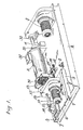
- Fig. 1 is a perspective view of apparatus for crushing and washing ballast and sand according to the present invention; and
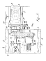
- Fig. 2 is a plan view of part of the apparatus shown in Fig. 1.
- In the drawings, reference numeral 1 denotes a base. Mounted on the upper surface of the base 1 is a two-layer structure comprising a lateral cylindrical body 2 having detachably attached to the internal surface thereof a lining (not shown).
- Disposed on the central longitudinal axis of the cylindrical body 2 is a rotatable
main shaft 4 having attached at the periphery thereof a plurality of crush blades 3 disposed within the cylindrical body 2. Themain shaft 4 extends from near the front end of the cylindrical body 2 outwardly from the rear end of the cylindrical body 2 and is supported on the base 1 in cantilever fashion by spaced apartbearings 32. A drive motor 5 is connected to themain shaft 4 through a chain (not shown). - The base 1 is provided thereon with a plurality of rollers 8 arranged in two rows and engaged in
respective guide grooves 7 formed in opposed sides of a substantially reversed U-shaped slide table 6 to support slidably the table 6 on the base 1. The engagement of the rollers 8 in theguide grooves 7 is concealed byrespective cover frames 9. - A
rotatable jack shaft 10 carried by spaced apartbearings 11 on the slide table 6 is disposed on the coaxis of the cylindrical body 2 in alignment with themain shaft 4. One end of thejack shaft 10 is attached with a cone-shaped crush bowl 13 having acollar 12 for co-operating with adischarge port 29 at the front end of the cylindrical body 2. The other end of thejack shaft 10 is engaged with apressure member 14. - The
jack shaft 10 is provided with asprocket 16 between thebearings 11. Thesprocket 16 is connected to asprocket 17 mounted on adrive motor 15 on the slide table 6 through achain 18. Thechain 18 is covered with achain cover 19. - Between the under surface of the slide table 6 and the upper surface of the base 1, a threaded
sleeve 21 is engaged with a threadedshaft 25 carried at one end on a bearing on the base 1 and engaged at the other end with anoperation handle 27 through abevel gear meachanism 26. One end of aspring 22 is secured to spring bearing 23 integral with thesleeve 21 and the other end thereof is carried by abearing sleeve 24 secured to the under surface of the slide table 6 at that end near to the cylindrical body 2. Due to this arrangement the slide table 6 is movable towards the cylindrical body 2 on actuation of thehandle 27 to move thesleeve 21 and spring bearing 23 towards the body 2 thereby pressurising thespring 22. - Disposed on the upper surface of the base 1 is an adjustable stop provided by threaded
shaft 28 carried by a bearing. Theshaft 28 is engageable with the slide table 6 to limit movement of the slide table 6 towards the cylindrical body 2. Due to the foregoing arrangement, the degree of engagement between thecrush bowl 13 and thedischarge port 29 at the front end of the cylindrical body is adjustable. In addition, the biassing effect of thespring 22 on the table 6 and thecrush bowl 13 carried thereby is also adjustable at the limit position of the table 6. - The cylindrical body 2 is provided at the front end with a
feed water port 30 near to thedischarge port 29 and at the rear end with aballast feed port 31 on the upper portion thereof. - When ballast and sand are crushed and washed by using the apparatus according to the present invention, the
operation handle 27 is rotated to move the slide table 6 towards the cylindrical body 2 as far as the limit position set by the engagement of the slide table 6 with theshaft 28 to provide the required degree of engagement between thecrush bowl 13 anddischarge port 29. - In the limit position, the biassing force of the
coil spring 22 acting on the slide table 6 and the hence thecrush bowl 13 may be set to any required level by further rotation of thecontrol handle 27 to compress thespring 22. - Next the
drive motors 5,15 are actuated causing themain shaft 4 and thejack shaft 10 to rotate in opposite directions and the collected ballast is fed into the cylindrical body 2 through theballast feed port 31 while feeding water therein through thewater feed port 30. - The ballast is transferred toward the
discharge port 29 while being agitated by the crush blades 3 spirally disposed on the rotarymain shaft 4 where it is strongly rubbed against thecrush bowl 13 rotating in the opposite direction by pressure of the succeeding ballast. - As a result, the ballast pushes back the
crush bowl 13 together with the slide table 6 away from thedischarge port 29 against the force of thespring 22 creating a space between thecrush bowl 13 and thedischarge port 29 through which the ballast is discharged. - The ballast is discharged after soft stones, lumps of tough loam, lumps of clay, etc. mixed in the ballast are completely crushed and angular corners of the crushed stones and dusts attached to the ballast are completely removed due to the crushing effect of the crush blades 3, the
crush bowl 13 rotating within the cylindrical body 2 and the rubbing effect among the ballast and the like. As a result, a mass production of high quality ballast washed by water fed through thefeed water port 30 can be obtained in an efficient manner. - Further, since the pressure applied by the ballast to the
crush bowl 13 is dumped through thecoil spring 22 disposed on the slide table 6, mechanical wear is extremely small and the apparatus can operate for a long time without problems. In addition maintenance is easy. - Moreover, since the degree of engagement between the
crush bowl 13 and thedischarge port 29 at the front end of the cylindrical body 2 and the biassing force of thecoil spring 22 are adjustable by operating theoperation handle 27 and thestop shaft 28, when in use, the degree of engagement of thecrush bowl 13 and the biassing force of thecoil spring 22 can be properly adjusted depending on quality of the ballast. - Although in the exemplary embodiment above-described the apparatus is used for crushing and washing ballast and sand, it will be understood that the apparatus may be used for crushing and washing other materials, for example concrete structures or glass products.
Claims (10)
Priority Applications (1)
| Application Number | Priority Date | Filing Date | Title |
|---|---|---|---|
| AT86109978T ATE52202T1 (en) | 1985-09-25 | 1986-07-21 | APPARATUS FOR CRUSHING AND WASHING GRAVEL, SAND AND THE LIKE. |
Applications Claiming Priority (2)
| Application Number | Priority Date | Filing Date | Title |
|---|---|---|---|
| JP146474/85U | 1985-09-25 | ||
| JP1985146474U JPS6246438Y2 (en) | 1985-09-25 | 1985-09-25 |
Publications (3)
| Publication Number | Publication Date |
|---|---|
| EP0216059A2 true EP0216059A2 (en) | 1987-04-01 |
| EP0216059A3 EP0216059A3 (en) | 1988-06-08 |
| EP0216059B1 EP0216059B1 (en) | 1990-04-25 |
Family
ID=15408456
Family Applications (1)
| Application Number | Title | Priority Date | Filing Date |
|---|---|---|---|
| EP86109978A Expired - Lifetime EP0216059B1 (en) | 1985-09-25 | 1986-07-21 | Apparatus for crushing and washing ballast, sand and the like |
Country Status (4)
| Country | Link |
|---|---|
| EP (1) | EP0216059B1 (en) |
| JP (1) | JPS6246438Y2 (en) |
| AT (1) | ATE52202T1 (en) |
| DE (1) | DE3670581D1 (en) |
Cited By (2)
| Publication number | Priority date | Publication date | Assignee | Title |
|---|---|---|---|---|
| CN108393184A (en) * | 2018-01-25 | 2018-08-14 | 谢燕玲 | A kind of build concrete processing flour mill |
| CN114571621A (en) * | 2021-12-29 | 2022-06-03 | 江苏德力化纤有限公司 | Preparation device and use method of hydrophilic polyester fiber with light absorption and heating functions |
Citations (8)
| Publication number | Priority date | Publication date | Assignee | Title |
|---|---|---|---|---|
| DE200322C (en) * | ||||
| NL23730C (en) * | ||||
| DE531681C (en) * | 1930-05-20 | 1931-09-01 | Gewerk Eisenhuette Westfalia | Cleaning trolley for old track beds |
| GB477776A (en) * | 1936-07-03 | 1938-01-03 | Carolus Maria Joseph Antonius | Improved process and apparatus for breaking up mineral-containing clay, loam or the like masses by washing |
| GB1145605A (en) * | 1966-04-04 | 1969-03-19 | Viktor Seidl | Machine for cleaning railbed ballast |
| SU810300A2 (en) * | 1979-04-06 | 1981-03-07 | Сибирский Государственный Проектныйи Научно-Исследовательскийинститут Цветной Металлургии | Apparatus for wet screening and cleaning of gravel and crushed stone |
| EP0079867A1 (en) * | 1981-11-12 | 1983-05-25 | Palmiero Capannoli | Washing apparatus for inert materials such as sand, gravel and the like |
| JPH0634750A (en) * | 1992-07-22 | 1994-02-10 | Mitsubishi Heavy Ind Ltd | Ground relief state analyzing device |
-
1985
- 1985-09-25 JP JP1985146474U patent/JPS6246438Y2/ja not_active Expired
-
1986
- 1986-07-21 EP EP86109978A patent/EP0216059B1/en not_active Expired - Lifetime
- 1986-07-21 DE DE8686109978T patent/DE3670581D1/en not_active Expired - Fee Related
- 1986-07-21 AT AT86109978T patent/ATE52202T1/en not_active IP Right Cessation
Patent Citations (8)
| Publication number | Priority date | Publication date | Assignee | Title |
|---|---|---|---|---|
| DE200322C (en) * | ||||
| NL23730C (en) * | ||||
| DE531681C (en) * | 1930-05-20 | 1931-09-01 | Gewerk Eisenhuette Westfalia | Cleaning trolley for old track beds |
| GB477776A (en) * | 1936-07-03 | 1938-01-03 | Carolus Maria Joseph Antonius | Improved process and apparatus for breaking up mineral-containing clay, loam or the like masses by washing |
| GB1145605A (en) * | 1966-04-04 | 1969-03-19 | Viktor Seidl | Machine for cleaning railbed ballast |
| SU810300A2 (en) * | 1979-04-06 | 1981-03-07 | Сибирский Государственный Проектныйи Научно-Исследовательскийинститут Цветной Металлургии | Apparatus for wet screening and cleaning of gravel and crushed stone |
| EP0079867A1 (en) * | 1981-11-12 | 1983-05-25 | Palmiero Capannoli | Washing apparatus for inert materials such as sand, gravel and the like |
| JPH0634750A (en) * | 1992-07-22 | 1994-02-10 | Mitsubishi Heavy Ind Ltd | Ground relief state analyzing device |
Non-Patent Citations (1)
| Title |
|---|
| SOVIET INVENTIONS ILLUSTRATED, week D49, 20th January 1982, class P41,P43, Derwent Publications Ltd, London, GB; & SU-A-810 300 (FERR METAL RES.) 09-04-1981 * |
Cited By (3)
| Publication number | Priority date | Publication date | Assignee | Title |
|---|---|---|---|---|
| CN108393184A (en) * | 2018-01-25 | 2018-08-14 | 谢燕玲 | A kind of build concrete processing flour mill |
| CN108393184B (en) * | 2018-01-25 | 2019-09-10 | 无锡市新兴建筑工程有限公司 | A kind of build concrete processing flour mill |
| CN114571621A (en) * | 2021-12-29 | 2022-06-03 | 江苏德力化纤有限公司 | Preparation device and use method of hydrophilic polyester fiber with light absorption and heating functions |
Also Published As
| Publication number | Publication date |
|---|---|
| DE3670581D1 (en) | 1990-05-31 |
| EP0216059A3 (en) | 1988-06-08 |
| ATE52202T1 (en) | 1990-05-15 |
| JPS6256140U (en) | 1987-04-07 |
| EP0216059B1 (en) | 1990-04-25 |
| JPS6246438Y2 (en) | 1987-12-15 |
Similar Documents
| Publication | Publication Date | Title |
|---|---|---|
| US7581689B2 (en) | Device for processing excavated material | |
| US4624605A (en) | Shield tunneling apparatus | |
| CN210303830U (en) | Raw stone crushing device for mine | |
| CN112473799B (en) | Medicine production and processing is with smashing grinder | |
| EP0216059B1 (en) | Apparatus for crushing and washing ballast, sand and the like | |
| US3734148A (en) | Grinder | |
| US2235446A (en) | Surfacing means | |
| CN213826875U (en) | Sand mixer for producing refractory material | |
| US3633833A (en) | Machine with self-sharpening means for cutting scrap materials into chips | |
| CN213825242U (en) | Waste material breaker for civil engineering | |
| ES420388A1 (en) | Jaw crusher | |
| US2058731A (en) | Granite cutting machine | |
| CN209061273U (en) | The vertical type Chinese medicinal material crushing and processing cylinder of function is chosen with varus | |
| CN208466052U (en) | Device is stirred in a kind of band fish meal environmental protection rotation | |
| JP3131873B2 (en) | Coarse crusher | |
| EP0232453B1 (en) | Apparatus for crushing and washing ballast and the like | |
| NO850770L (en) | CRUSHING AND GRINDING MACHINE WITH TWO CONS | |
| JPH0615188A (en) | Crushing device | |
| CN220460532U (en) | Apparatus for producing of preparation alkali-free liquid accelerator | |
| CN117443524B (en) | Vertical pulverizer for pharmaceutical processing | |
| CN210850438U (en) | Double-screw granulator blank device | |
| JPH0248040Y2 (en) | ||
| CN214557355U (en) | Double-component full-automatic casting machine with sand adding mechanism | |
| JPH0765288B2 (en) | Wet concrete cutter device | |
| EP0214419A2 (en) | Apparatus for washing sand and the like |
Legal Events
| Date | Code | Title | Description |
|---|---|---|---|
| PUAI | Public reference made under article 153(3) epc to a published international application that has entered the european phase |
Free format text: ORIGINAL CODE: 0009012 |
|
| AK | Designated contracting states |
Kind code of ref document: A2 Designated state(s): AT BE CH DE FR GB IT LI LU NL SE |
|
| PUAL | Search report despatched |
Free format text: ORIGINAL CODE: 0009013 |
|
| AK | Designated contracting states |
Kind code of ref document: A3 Designated state(s): AT BE CH DE FR GB IT LI LU NL SE |
|
| 17P | Request for examination filed |
Effective date: 19880711 |
|
| 17Q | First examination report despatched |
Effective date: 19880906 |
|
| GRAA | (expected) grant |
Free format text: ORIGINAL CODE: 0009210 |
|
| AK | Designated contracting states |
Kind code of ref document: B1 Designated state(s): AT BE CH DE FR GB IT LI LU NL SE |
|
| REF | Corresponds to: |
Ref document number: 52202 Country of ref document: AT Date of ref document: 19900515 Kind code of ref document: T |
|
| REF | Corresponds to: |
Ref document number: 3670581 Country of ref document: DE Date of ref document: 19900531 |
|
| ET | Fr: translation filed | ||
| ITF | It: translation for a ep patent filed |
Owner name: STUDIO MASSARI S.R.L. |
|
| PLBE | No opposition filed within time limit |
Free format text: ORIGINAL CODE: 0009261 |
|
| STAA | Information on the status of an ep patent application or granted ep patent |
Free format text: STATUS: NO OPPOSITION FILED WITHIN TIME LIMIT |
|
| 26N | No opposition filed | ||
| PGFP | Annual fee paid to national office [announced via postgrant information from national office to epo] |
Ref country code: GB Payment date: 19930707 Year of fee payment: 8 |
|
| PGFP | Annual fee paid to national office [announced via postgrant information from national office to epo] |
Ref country code: FR Payment date: 19930709 Year of fee payment: 8 |
|
| PGFP | Annual fee paid to national office [announced via postgrant information from national office to epo] |
Ref country code: SE Payment date: 19930719 Year of fee payment: 8 Ref country code: BE Payment date: 19930719 Year of fee payment: 8 |
|
| PGFP | Annual fee paid to national office [announced via postgrant information from national office to epo] |
Ref country code: LU Payment date: 19930730 Year of fee payment: 8 Ref country code: AT Payment date: 19930730 Year of fee payment: 8 |
|
| ITTA | It: last paid annual fee | ||
| PGFP | Annual fee paid to national office [announced via postgrant information from national office to epo] |
Ref country code: NL Payment date: 19930731 Year of fee payment: 8 |
|
| PGFP | Annual fee paid to national office [announced via postgrant information from national office to epo] |
Ref country code: CH Payment date: 19930805 Year of fee payment: 8 |
|
| PGFP | Annual fee paid to national office [announced via postgrant information from national office to epo] |
Ref country code: DE Payment date: 19930929 Year of fee payment: 8 |
|
| EPTA | Lu: last paid annual fee | ||
| PG25 | Lapsed in a contracting state [announced via postgrant information from national office to epo] |
Ref country code: LU Free format text: LAPSE BECAUSE OF NON-PAYMENT OF DUE FEES Effective date: 19940721 Ref country code: GB Effective date: 19940721 Ref country code: AT Effective date: 19940721 |
|
| PG25 | Lapsed in a contracting state [announced via postgrant information from national office to epo] |
Ref country code: SE Effective date: 19940722 |
|
| PG25 | Lapsed in a contracting state [announced via postgrant information from national office to epo] |
Ref country code: LI Effective date: 19940731 Ref country code: CH Effective date: 19940731 Ref country code: BE Effective date: 19940731 |
|
| BERE | Be: lapsed |
Owner name: MARUKO JARI HAMBAI CO. LTD Effective date: 19940731 |
|
| EUG | Se: european patent has lapsed |
Ref document number: 86109978.6 Effective date: 19950210 |
|
| PG25 | Lapsed in a contracting state [announced via postgrant information from national office to epo] |
Ref country code: NL Effective date: 19950201 |
|
| NLV4 | Nl: lapsed or anulled due to non-payment of the annual fee | ||
| GBPC | Gb: european patent ceased through non-payment of renewal fee |
Effective date: 19940721 |
|
| PG25 | Lapsed in a contracting state [announced via postgrant information from national office to epo] |
Ref country code: FR Effective date: 19950331 |
|
| REG | Reference to a national code |
Ref country code: CH Ref legal event code: PL |
|
| PG25 | Lapsed in a contracting state [announced via postgrant information from national office to epo] |
Ref country code: DE Effective date: 19950401 |
|
| EUG | Se: european patent has lapsed |
Ref document number: 86109978.6 |
|
| REG | Reference to a national code |
Ref country code: FR Ref legal event code: ST |
|
| PG25 | Lapsed in a contracting state [announced via postgrant information from national office to epo] |
Ref country code: IT Free format text: LAPSE BECAUSE OF NON-PAYMENT OF DUE FEES;WARNING: LAPSES OF ITALIAN PATENTS WITH EFFECTIVE DATE BEFORE 2007 MAY HAVE OCCURRED AT ANY TIME BEFORE 2007. THE CORRECT EFFECTIVE DATE MAY BE DIFFERENT FROM THE ONE RECORDED. Effective date: 20050721 |