EP0216048A2 - Regulation method for a direct current high-voltage power transmission between two three-phase networks - Google Patents
Regulation method for a direct current high-voltage power transmission between two three-phase networks Download PDFInfo
- Publication number
- EP0216048A2 EP0216048A2 EP86109776A EP86109776A EP0216048A2 EP 0216048 A2 EP0216048 A2 EP 0216048A2 EP 86109776 A EP86109776 A EP 86109776A EP 86109776 A EP86109776 A EP 86109776A EP 0216048 A2 EP0216048 A2 EP 0216048A2
- Authority
- EP
- European Patent Office
- Prior art keywords
- control
- voltage
- network
- mvar
- networks
- Prior art date
- Legal status (The legal status is an assumption and is not a legal conclusion. Google has not performed a legal analysis and makes no representation as to the accuracy of the status listed.)
- Granted
Links
Images
Classifications
-
- H—ELECTRICITY
- H02—GENERATION; CONVERSION OR DISTRIBUTION OF ELECTRIC POWER
- H02J—CIRCUIT ARRANGEMENTS OR SYSTEMS FOR SUPPLYING OR DISTRIBUTING ELECTRIC POWER; SYSTEMS FOR STORING ELECTRIC ENERGY
- H02J3/00—Circuit arrangements for ac mains or ac distribution networks
- H02J3/36—Arrangements for transfer of electric power between ac networks via a high-tension dc link
-
- Y—GENERAL TAGGING OF NEW TECHNOLOGICAL DEVELOPMENTS; GENERAL TAGGING OF CROSS-SECTIONAL TECHNOLOGIES SPANNING OVER SEVERAL SECTIONS OF THE IPC; TECHNICAL SUBJECTS COVERED BY FORMER USPC CROSS-REFERENCE ART COLLECTIONS [XRACs] AND DIGESTS
- Y02—TECHNOLOGIES OR APPLICATIONS FOR MITIGATION OR ADAPTATION AGAINST CLIMATE CHANGE
- Y02E—REDUCTION OF GREENHOUSE GAS [GHG] EMISSIONS, RELATED TO ENERGY GENERATION, TRANSMISSION OR DISTRIBUTION
- Y02E60/00—Enabling technologies; Technologies with a potential or indirect contribution to GHG emissions mitigation
- Y02E60/60—Arrangements for transfer of electric power between AC networks or generators via a high voltage DC link [HVCD]
Definitions
- the invention relates to a control method for an HGU connecting two three-phase networks according to the preamble of patent claim 1.
- the active power of the HGU is regulated and the reactive power is adapted to the reactive power requirement of the respective three-phase network using switchable chokes or capacitors, static compensators (e.g. thyristor-controlled chokes or capacitors) and / or drive-less rotating synchronous machines.
- switchable chokes or capacitors static compensators (e.g. thyristor-controlled chokes or capacitors) and / or drive-less rotating synchronous machines.
- static compensators e.g. thyristor-controlled chokes or capacitors
- / or drive-less rotating synchronous machines e.g. thyristor-controlled chokes or capacitors
- a considerable effort is required for a necessary fine-level or infinitely variable voltage adaptation to the active power to be transmitted.
- the invention has for its object to provide a much faster control for both sides of the HGU and to determine an operating point that allows compliance with the specified network conditions for both three-phase networks and that allows rapid determination of a new operating point in both dynamic processes due to change
- switchable simple L or C compensation means are sufficient in addition to fixed compensation means.
- the control method according to the invention is based on the reactive power requirement to be specified by the network operator in both three-phase networks, the function of the respectively required network voltage and the required transmission power of the HGU, these values being adapted to the actual network conditions when the HGU is started up.
- the permissible voltage range and the provided fixed and switchable compensation means as well as the transformer switching stages and the voltage-dependent reactive power requirement of each three-phase network result in a range in a reactive power-active power diagram for the converters, within which operating points are determined during stationary operation that meet all network conditions.
- Capacitive or inductive compensation means are switched on or off when the above range is undershot or undershot. In the case of dynamic processes, the operating point may also lie outside the range mentioned.
- the direct current determined for the side of the HGU assigned to this three-phase network can be set as a transmission current.
- the reactive power of the other three-phase network then deviates more from the setpoint.
- switching capacitors or chokes changes the reactive power of one or both inverters so that the position of the transformer tap changer assigned to them is one when determining the operating data for the two inverters has the smallest possible difference.
- the switching stages for each converter and the direct currents of the converters are determined using the specified network data and the operating data, and the lowest possible common direct current that is sufficient to meet all conditions of both networks is preferably determined from these.
- the optimum operating point is advantageously determined by controlling the tap changer combination determined according to the method according to the invention, so that fine tuning by means of a static compensator or a reactive power machine is unnecessary.
- the operating data associated with the three-phase networks 1 and 2 are designated with corresponding indices and also with further indices N and n, of which the index N indicates network sizes and the index n denotes nominal values.
- an operating range between 90 and 155 MVAr is determined for full and partial loads with the available compensating means (filter circuits and switchable compensating means), the manufacturer's information for the step transformers and the voltage-dependent reactive power requirements of the three-phase networks, which ensures safe operation for all operational requirements and which has sufficient control reserves in both directions in dynamic processes.
- the tap changer setting for each HGU converter can be
- the transmission ratio ü of the network 2 N 2 associated load tap is 0.9 times as large as the ratio u 1 of the network N 1 associated transformer tap changer and there are thus defined the possible combinations of stages.
- both stage transformers are the same and each have 35 switching stages.
- I dmin the lowest permissible direct current I dmin
- one of the two step transformers is always at the highest permissible step for this mains voltage, in this case step 35 of the step transformer of the network N1, since ü 2 ⁇ ü 1 .
- step number ratios such as 3 4/27, 33/26 or 32/25 can also be used, with I dmin having an increasingly larger amount. It should be noted that the current I dmin increasing with decreasing steps may only increase so permissively by reducing the steps that it does not exceed the specified nominal value I dn or the control angles ⁇ , the deletion angles ⁇ and the overlap angles u their permissible limits adhere to.
- I dmin can flow in conjunction with the permissible switching stage ratio , whereby minor deviations in the setpoints for the active and reactive power can be corrected with the control or extinction angle if necessary.
- control method according to the invention can run both analog and digital and, as explained, allows the determination of the optimal operating point for stationary operating cases and the operating point with the slightest deviation from the target values for both networks during dynamic processes in the networks.
- An application of the invention is possible in the manner described below not only for two predetermined networks coupled by the HGU N1 and N2 according to FIG. 1, but also for the cooperation of networks, of which at least one network can receive different expansion levels and thereby Requirement should be met that the step transformers for the converters, the reactive power control for the HGU and the determined compensation means in the form of chokes and capacitors are sufficient for all network configurations.
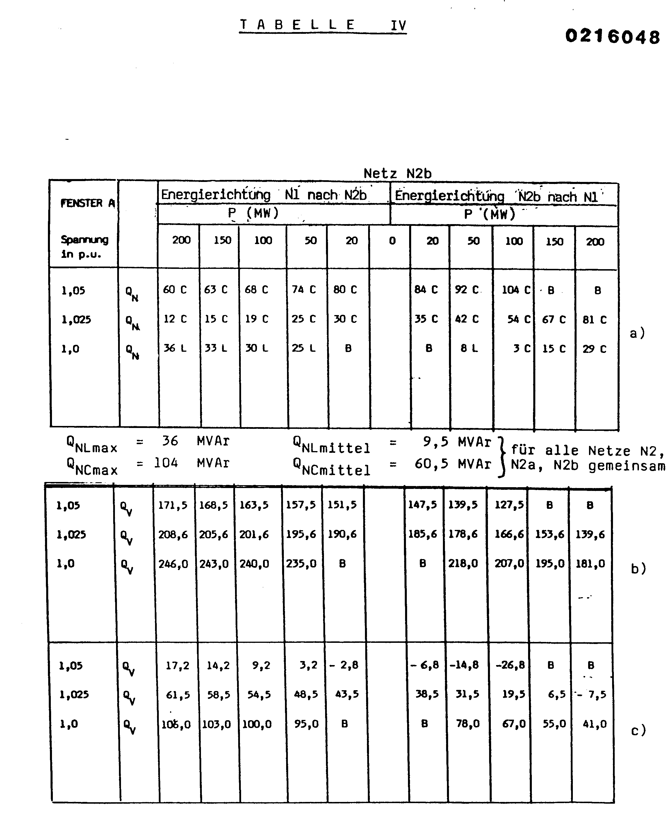
- the network N1 should remain unchanged and the network N2 should be gradually expanded to the network N2a and finally in a further stage to the network N2b.
- each network is permanently connected to a constant filter circuit FK1 and FK2 for eliminating harmonics.
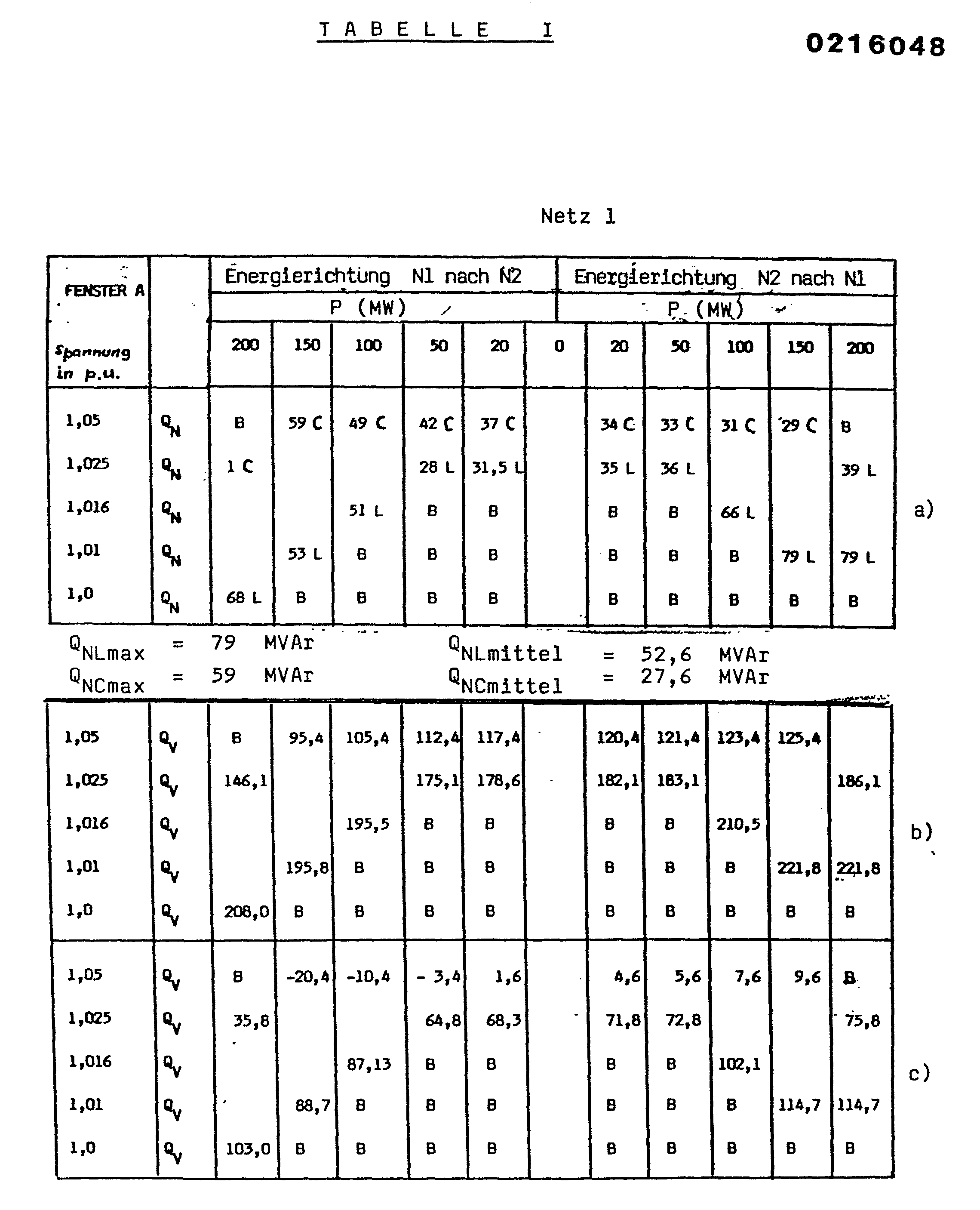
- the operator accepts network voltage limits as voltage windows A and only areas B permitted for dynamic processes in accordance with FIG. 4 and the associated network reactive powers Q N given according to Tables Ia to IVa. From tables Ia to IVa, maximum and minimum, inductive or capacitive grid reactive power values can be found for favorable and unfavorable grid conditions.
- the mean values for inductive or capacitive Netzblindlei power can be calculated and summed for the networks N2, N2a, N 2 b and divided by three.
- the respective values for Q NLmax , Q NCmax ; Q NLmitttel and Q NCstoff are entered in Tables Ia to IVa.
- Tables Ib, c to IVb, c each show the largest and smallest values of the converter reactive powers Q V for the various networks and energy directions in the HGU under favorable and unfavorable network conditions, which are calculated in the manner specified below.
- the minimum values Q V should be the maximum permitted busbar voltage for the respective active power P, calculated to the g ehö- ring network reactive power demand Q N and all inductive compensation means L. In this case, the effect of the chokes is supported by the respective network.
- the maximum values Q v are determined using the minimum permissible busbar voltage for the active power in question P Soll (P n ), the associated grid reactive power requirement Q N and all capacitive compensation means.
- the inner upper limit of Q vtop each network is intended with the maximum permissible voltage busbar with a corresponding active power P, calculates the associated Q N and all associated capacitive compensation means.
- the inner lower limit Q vbottom of each network is to the minimum permissible each busbar voltage (window A) for the corresponding active power P, calculated to the associated Q N and all known inductive compensation means.
- the reactive power requirement QN must be covered by the capacitors and the filter circuits FK to such an extent that Q v is within the operating range.
- the required converter reactive power can be derived from this and from the difference determine the reactive power swing ⁇ Q V of the step transformers.
- the N etzblindieres the respectively cooperating two networks must be compensated for so far that the Umrichterblindminister are within the operating range, that is, that their difference is smaller than ⁇ Q V.
- the converter reactive powers can then be brought closer to one another.
- the transmission of the smallest converter direct currents I d and thus the minimization of the transmission losses of the HGU is achieved when the converter reactive powers of both converters UR1, UR2 are at the lower limit of the respective operating range.
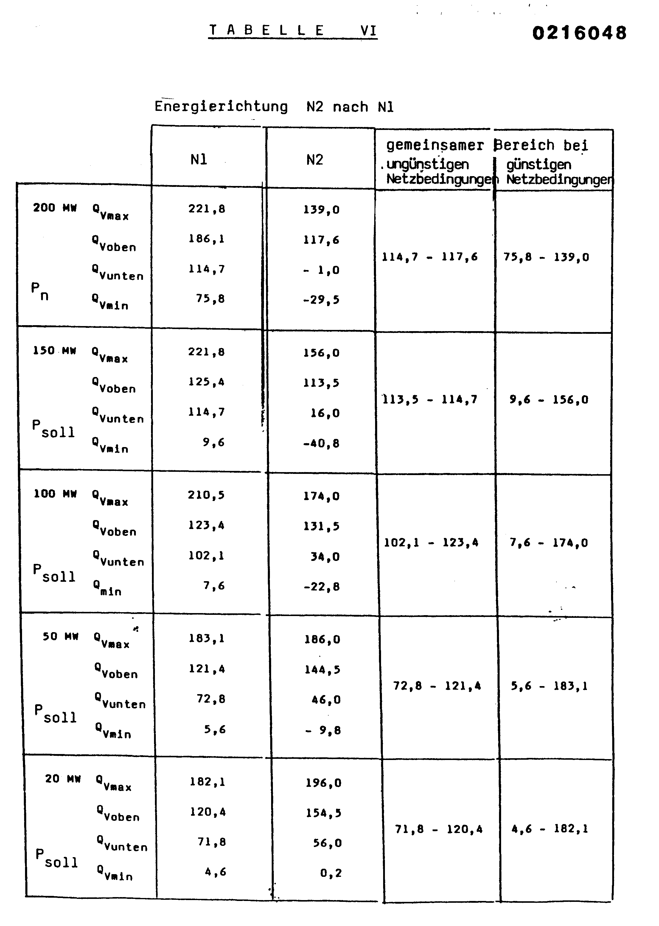
- Tables Ib, c to IVb, c are shown in Tables V to X in such a way that the individual networks N1, N2; N2a, N2b result in common areas from which, according to Table XI, common valid operating areas are taken for all networks, which show that a common operating area determined according to the invention for the HGU with reactive power control while maintaining a sufficient control reserve in the event of network faults, dynamic processes in the network and rapid changes in performance of the generators in the networks (power ramps) is guaranteed with the step transformers used and the selected compensation means.
Landscapes
- Engineering & Computer Science (AREA)
- Power Engineering (AREA)
- Control Of Electrical Variables (AREA)
- Ac-Ac Conversion (AREA)
- Supply And Distribution Of Alternating Current (AREA)
- Emergency Protection Circuit Devices (AREA)
Abstract
Description
Die Erfindung betrifft ein Regelverfahren für eine zwei Drehstromnetze verbindende HGU nach dem Oberbegriff des Patentanspruchs 1.The invention relates to a control method for an HGU connecting two three-phase networks according to the preamble of
Bei bekannten Regelverfahren für eine HGU wird eine Regelung der Wirkleistung der HGU vorgenommen und die Blindleistung an den Blindleistungsbedarf des jeweiligen Drehstromnetzes mit Hilfe von schaltbaren Drosseln oder Kondensatoren, statischen Kompensatoren (z.B. thyristorgesteuerte Drosseln oder Kondensatoren) und/oder antriebslosen rotierenden Synchronmaschinen angepaßt. Für die besagten steuerbaren Kompensationseinrichtungen ist für eine notwendige feinstufige oder stufenlose Spannungsanpassung an die zu übertragende Wirkleistung ein erheblicher Aufwand erforderlich. Außerdem ist ein Schalten des dem jeweiligen Umrichter zugeordneten Transformator-Stufenschalters der HGU in die falsche Richtung möglich, ehe die Regelanordnung feststellen kann, daß Kompensationseinrichtungen geschaltet werden müssen, so daß der Stufenschalter nach dem von ihm unabhängig erfolgten Schalten der betreffenden Kompensationseinrichtung wieder in Richtung seiner Ausgangsstellung zurückgeschaltet werden muß, wobei sogar ein Schalten über seine Ausgangsposition notwendig werden kann. Der Regelvorgang mit nacheinander ablaufenden Schaltbetätigungen der betreffenden Stufenschalter erlaubt nur eine langsame Regelung, wobei während der relativ lang dauernden Schaltvorgänge die geforderte Wirk- und Blindleistung nicht eingehalten werden kann.In known control methods for an HGU, the active power of the HGU is regulated and the reactive power is adapted to the reactive power requirement of the respective three-phase network using switchable chokes or capacitors, static compensators (e.g. thyristor-controlled chokes or capacitors) and / or drive-less rotating synchronous machines. For said controllable compensation devices, a considerable effort is required for a necessary fine-level or infinitely variable voltage adaptation to the active power to be transmitted. In addition, it is possible to switch the transformer tap changer of the HGU assigned to the respective converter in the wrong direction before the control arrangement can determine that compensation devices have to be switched, so that the tap changer returns to its direction after switching the relevant compensation device independently of it Starting position must be switched back, and switching to its starting position may even be necessary. The control process with sequential switching operations of the relevant tap changer allows only slow control, and the required active and reactive power cannot be maintained during the relatively long switching processes.
Überdies wird der betreffende Stufenschalter durch das Hin- und Herschalten unnötig beansprucht.In addition, the relevant tap changer is unnecessarily stressed by switching back and forth.
Um die Regelzeit nicht weiter zu verlängern, wird vielfach nur die mit dem schwächeren Drehstromnetz verbundene Seite der HGU im Sinne einer Einhaltung der vorgegebenen Bedingungen dieses Netzes geregelt und die dem stärkeren Drehstromnetz zugeordnete andere Seite der HGU wird blindleistungsmäßig nur über die schaltbaren Kompensationsmittel an den Bedarf angenähert, so daß im zweiten Drehstromnetz die dort geforderte Blindleistung nicht eingehalten werden kann, was beim ebenfalls relativ schwachen zweiten Drehstromnetz zu Ausfällen führen kann. Weiterhin kann dieses Verfahren ein Regeln in unerwünschte Grenzbereiche nicht erkennen, so daß bei Änderungen in der Soll-Leistung oder bei Spannungsänderungen in den Netzen keine ausreichende Regelreserve vorhanden ist. Eine bei zwei schwachen Netzen erforderliche gleiche langsame Regelung auch auf der Seite des zweiten Drehstromnetzes ergibt eine weitere Verlangsamung der Regelung.In order not to prolong the control time, in many cases only the side of the HGU connected to the weaker three-phase network is regulated in the sense of compliance with the specified conditions of this network and the other side of the HGU assigned to the stronger three-phase network is only required in terms of reactive power via the switchable compensation means approximated so that the reactive power required there cannot be maintained in the second three-phase network, which can lead to failures in the likewise relatively weak second three-phase network. Furthermore, this method cannot detect regulation in undesired limit ranges, so that there is insufficient control reserve in the event of changes in the nominal power or in the event of voltage changes in the networks. The same slow regulation required on two weak networks also on the side of the second three-phase network results in a further slowdown of the regulation.
Der Erfindung liegt die Aufgabe zugrunde, eine wesentlich schnellere Regelung für beide Seiten der HGU zu schaffen und einen Betriebspunkt zu ermitteln, der für beide Drehstromnetze die vorgegebenen Netzbedingungen einzuhalten ermöglicht und der bei änderungsbedingten dynamischen Vorgängen die schnelle Ermittlung eines neuen Betriebspunktes gestattet, der auf beiden Seiten der HGU die kleinstmöglichen Abweichungen von den jeweiligen Sollwerten von Netzspannung und Blindleistung des Netzes ergibt, wobei neben festen Kompensationsmitteln schaltbare einfache L bzw. C- Kompensationsmittel genügen.The invention has for its object to provide a much faster control for both sides of the HGU and to determine an operating point that allows compliance with the specified network conditions for both three-phase networks and that allows rapid determination of a new operating point in both dynamic processes due to change On the part of the HGU, the smallest possible deviations from the respective nominal values of the mains voltage and reactive power of the network result, whereby switchable simple L or C compensation means are sufficient in addition to fixed compensation means.
Die Lösung der gestellten Aufgabe gelingt durch die kennzeichnenden Merkmale des Anspruches 1.The problem is solved by the characterizing features of
Das Regelverfahren nach der Erfindung geht von den vom Netzbetreiber anzugebenden Blindleistungsbedarf in beiden Drehstromnetzen, der in Abhängigkeit von der jeweils geforderten Netzspannung sowie von der geforderten Ubertragungsleistung der HGU aus, wobei bei der Inbetriebnahme der HGU diese Werte den tatsächlichen Netzverhältnissen angepaßt werden. Aus dem zulässigen Spannungsbereich und den vorgesehenen festen und schaltbaren Kompensationsmitteln sowie den Transformatorsschaltstufen und dem spannungsabhängigen Blindleistungsbedarf jedes Drehstromnetzes ergibt sich ein Bereich in einem Blindleistungs- Wirkleistungs-Diagramm für die Umrichter, innerhalb dessen bei stationärem Betrieb Betriebspunkte ermittelt werden, die alle Netzbedingungen erfüllen. Das Zu- oder Abschalten von kapazitiven oder induktiven Kompensationsmitteln erfolgt bei Uber- bzw. Unterschreiten des besagten Bereiches. Bei dynamischen Vorgängen darf der Betriebspunkt auch außerhalb des genannten Bereiches liegen.The control method according to the invention is based on the reactive power requirement to be specified by the network operator in both three-phase networks, the function of the respectively required network voltage and the required transmission power of the HGU, these values being adapted to the actual network conditions when the HGU is started up. The permissible voltage range and the provided fixed and switchable compensation means as well as the transformer switching stages and the voltage-dependent reactive power requirement of each three-phase network result in a range in a reactive power-active power diagram for the converters, within which operating points are determined during stationary operation that meet all network conditions. Capacitive or inductive compensation means are switched on or off when the above range is undershot or undershot. In the case of dynamic processes, the operating point may also lie outside the range mentioned.
Zur Stützung eines Drehstromnetzes kann der für die diesem Drehstromnetz zugeordneten Seite der HGU ermit telte Gleichstrom als Ubertragungsstrom eingestellt werden. Die Blindleistung des anderen Drehstromnetzes weicht dann entsprechend mehr vom Sollwert ab.To support a three-phase network, the direct current determined for the side of the HGU assigned to this three-phase network can be set as a transmission current. The reactive power of the other three-phase network then deviates more from the setpoint.
Bei ausreichend bemessenen Kompensationsmitteln wird durch Schalten von Kondensatoren oder Drosseln die Blindleistung eines oder beider Umrichter im Sinne einer Annäherung verändert, damit bei der Festlegung der Betriebsdaten für die beiden Umrichter die Stellung der ihnen zugeordneten Transformatorstufenschalter eine möglichst geringe Differenz aufweist. Schließlich werden mit den vorgegebenen Netzdaten und den Betriebsdaten die Schaltstufen für jeden Umrichter sowie die Gleichströme der Umrichter ermittelt und aus diesen vorzugsweise der kleinstmögliche gemeinsame Gleichstrom bestimmt, der zur Einhaltung aller Bedingungen beider Netze ausreicht.If the compensating means are adequately dimensioned, switching capacitors or chokes changes the reactive power of one or both inverters so that the position of the transformer tap changer assigned to them is one when determining the operating data for the two inverters has the smallest possible difference. Finally, the switching stages for each converter and the direct currents of the converters are determined using the specified network data and the operating data, and the lowest possible common direct current that is sufficient to meet all conditions of both networks is preferably determined from these.
Nach Grobeinstellung durch die Kompensationsmittel wird vorteilhafterweise der optimale Betriebspunkt durch Ansteuern der nach den erfindungsgemäßen Verfahren bestimmten Stufenschalterkombination ermittelt, so daß eine Feinabstimmung durch einen statischen Kompensator oder eine Blindleistungsmaschine überflüssig ist.After rough adjustment by the compensation means, the optimum operating point is advantageously determined by controlling the tap changer combination determined according to the method according to the invention, so that fine tuning by means of a static compensator or a reactive power machine is unnecessary.
Das Verfahren der Erfindung ermöglicht:
- a) ein gezieltes Ansteuern eines eindeutigen Betriebspunktes, der alle Netzbedingungen erfüllt,
- b) die Angabe von fehlenden oder von nicht benötigten Kompensationsmitteln bei baulichen Veränderungen der Drehstromnetze mit Änderungen deren Blindleistungsbedarfs,
- c) die Ermittlung eines anderen günstigen Betriebspunktes bei Ausfall oder Abschalten zu Wartungszwecken von Kompensatinonsmitteln sowie
- d) das Einstellen des günstigsten Betriebspunktes während auftretender Leistungs- oder Spannungsänderungen (dynamische Vorgänge) in der Zeitspanne, in der noch kein Kompensationsmittel und kein Stufenschalter schalten kann.
- a) targeted control of a clear operating point that meets all network conditions,
- b) the specification of missing or unnecessary compensation means in the event of structural changes to the three-phase networks with changes in their reactive power requirements,
- c) the determination of another favorable operating point in the event of failure or shutdown for maintenance purposes of compensating means and
- d) the setting of the most favorable operating point during occurring power or voltage changes (dynamic processes) in the period in which no compensation means and no step switch can switch.
Weitere Einzelheiten sind anhand eines Rechenbeispiels für eine nach den Regelverfahren der Erfindung betriebene HGU näher erläutert.
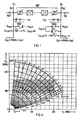
- In Fig. 1 ist schematisch eine zwei Drehstromnetze verbindende HGU-Kurzkupplung gezeigt mit festen Filterkreisen und schaltbaren Kompensationsmitteln.
- In Fig. 2 ist ein Wirk-Blindleistungsdiagramm für die HGU mit einem Wertepaarbereich gezeigt, in dem die HGU zur Erfüllung aller Betriebsbedingungen arbeitet und zwar in Abhängigkeit von Steuer- bzw. Löschwinkel und von übertragenen Gleichstrom bei Transformatorstufe 28 und einer Nenn-Netzspannung von 230 kV.
- Strength in F. 1 schematically shows an HGU close coupling connecting two three-phase networks with fixed filter circuits and switchable compensation means.
- 2 shows an active reactive power diagram for the H G U with a range of values in which the HGU works to meet all operating conditions, depending on the control or extinction angle and on the transmitted direct current at transformer stage 28 and a nominal mains voltage of 230 kV.
Die den Drehstromnetzen 1 und 2 zugehörigen Betriebsdaten sind mit entsprechenden Indizes bezeichnet und außerdem mit weiteren Indizes N und n, von denen der Index N auf Netzgrößen hinweist und der Index n Nennwerte bezeichnet.The operating data associated with the three-
Es bedeuten in den folgenden Angaben:
- Pn = Nennwirkleistung
- Psoll = Sollwirkleistung
- UN = Netzspannung (UN1, U N2' U Nn)
- UKn = Kurzschlußspannung des betreffenden Stufentransformators
- Id = Umrichtergleichstrom (Id1, Id2)
- Idmin = kleinster Ubertragungsgleichstrom der HGU, der die Netzbedingungen beider
Netze 1 und 2 sowie die Wirk- und Blindleistungsbedingungen in beiden Umrichtern erfüllt. - QN = Blindleistungsbedarf des Netzes (QN1, QN2)
- QV = erforderliche Blindleistung des Umrichters (QV1' Q V2)
- Qkap
- Qind = Kompensationsblindleistung
- = Kompensationsmittel schaltbar

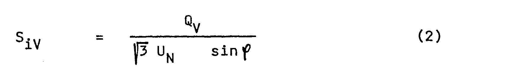
- SiV= Primärstrom des Stufentransformators
- FK = Filterkreis
- ü = Stufentransformator-Ubersetzungsverhältnis
- α = Steuerwinkel der Gleichrichterseite
- y = Löschwinkel der Wechselrichterseite
- u = Überlappungswinkel u = arc cos (cos α - uKn)- α


- P n = nominal active power
- P nominal = nominal active power
- UN = mains voltage (U N1 , U N2 ' U N n)
- U Kn = short-circuit voltage of the relevant step transformer
- I d = U mrichtergleichstrom (I d1, I d2)
- I dmin = smallest DC transmission current of the HGU that meets the network conditions of both
networks - QN = Bl indleistungsbedarf of the net (Q N1, N2 Q)
- Q V = required reactive power of the converter (Q V1 ' Q V 2)
- Qcap
- Q ind = compensation reactive power
- = Compensation means switchable
- S iV = primary current of the step transformer
- FK = filter circuit
- ü = step transformer ratio
- α = control angle of the rectifier side
- y = extinguishing angle on the inverter side
- u = overlap angle u = arc cos (cos α - u Kn ) - α
Für das nachstehend gezeigte Beispiel einer Anlage für eine Nennwirkleistung Pn = 200 MW, Psoll= 20 MW und einer Netznennspannung UNn = 230 kV sind die betreiberseitig angegebenen Forderungen für die Netze N1 und N2, nämlich
- QN1 = 33 MVAr (kapazitiv)
- QN2 = 40 MVAr (kapazitiv)
- UN1 = 241,5 kV entspricht

- UN2 = 234.6 kV entspricht

- Q N1 = 33 MVAr (capacitive)
- Q N2 = 40 MVAr (capacitive)
- U N1 = 241.5 kV
- U corresponds to N2 = 234.6 kV
Daraus lassen sich in bekannter Weise die notwendigen Kompensationsanordnungen in Form von nichtschaltbaren Filterkreisen FK sowie schaltbaren Kompensationsmittel C und L berechnen mit vorzugsweise für die Filterung von Oberschwingungen bestimmten
- FK1≡ QFK1 = 105 MVAr; zusätzlich ein schaltbarer Konden-sator C1≡ (Qkapl) = 35 MVAr
- FK2 ≡ QFK2 = 105 MVAr; zusätzlich ein schaltbarer Konden-sator C2≡ (Qkap2)= 35 MVAr
- FK 1 ≡ Q FK1 = 105 MVAr; additionally a switchable capacitor C 1 ≡ (Q ka p l ) = 35 MVAr
- FK 2 ≡ Q FK2 = 105 MVAr; additionally a switchable capacitor C 2 ≡ (Q kap2 ) = 35 MVAr
Für diese Ubertragung wird für Voll- und Teillasten mit den zur Verfügung stehenden Kompensationsmittel (Filterkreise und schaltbare Kompensationsmittel), den Herstellerangaben für die Stufentransformatoren sowie den spannungsabhängigen Blindleistungsanforderungen der Drehstromnetze ein Betriebsbereich zwischen 90 und 155 MVAr ermittelt, der für alle Betriebswünsche einen sicheren Betrieb gewährleistet und der bei dynamischen Vorgängen ausreichende Regelreserven in beiden Richtungen aufweist.For this transmission, an operating range between 90 and 155 MVAr is determined for full and partial loads with the available compensating means (filter circuits and switchable compensating means), the manufacturer's information for the step transformers and the voltage-dependent reactive power requirements of the three-phase networks, which ensures safe operation for all operational requirements and which has sufficient control reserves in both directions in dynamic processes.
Es ergibt sich folgendes für:The following results for:
Blindleistungsbedarf QN1= 33,0 MVAr (kapazitiv) bei UN1= 241,5 kV;(1,05 p.u.)Reactive power requirement Q N1 = 33.0 MVAr (capacitive) at U N1 = 241.5 kV; (1.05 pu)
Filterkreis FK1 mit QFK1 = 105 . 1,052= 115,76 MVAr C1 mit Qkap1= 35 . 1,052= 38,59 MVAr Filter circuit FK 1 with Q FK1 = 105. 1.05 2 = 115.76 MVAr C 1 with Q kap1 = 35. 1.05 2 = 38.59 MVAr
keine Drosseln erforderlich, d.h. Qind1= 0 no chokes required, ie Q ind1 = 0
Blindleistungsbedarf QN2 = 40,0 MVAr (kapazitiv bei U N2 = 234,6 kV; (1,02 p.u.)Reactive power requirement Q N2 = 40.0 MVAr (capacitive at U N2 = 234.6 kV; (1.02 p. U. )
Filterkreis FK2 mit QFK2 = 105 . 1,022= 109,24 MVAr C2 mit Qkap2 = 35 . 1,022= 36,41 MVAr Filter circuit FK 2 with Q FK2 = 105. 1.02 2 = 109.24 MVAr C 2 with Q ka p 2 = 35. 1.02 2 = 36.41 MVAr
Keine Drosseln notwendig, d.h. Qind2 = 0 Daraus ergibt sich:
- QV1 = QFK1+ QN1+ Qkap1- Qindl = 115,76 - 33,0 + 38,59 - 0 = 121,35 MVAr
- Q V2 = QFK2+ QN2+ Qkap2- Qind2= 109,24 - 40,0 + 36,41 - 0 = 105,66 MVAr
- Die errechneten Umrichterblindleistungen
- QV1= 121,35 MVAr und QV2 = 105,66 MVAr liegen im besagten Betriebsbereich zwischen 90 und 155 MVAr.
- Q V1 = Q FK1 + Q N1 + Q kap1 - Q i ndl = 115.76 - 33.0 + 38.59 - 0 = 121.35 MVAr
- Q V2 = Q FK2 + Q N2 + Q kap2 - Q ind2 = 109.24 - 40.0 + 36.41 - 0 = 105.66 MVAr
- The calculated converter reactive powers
- Q V1 = 121.35 MVAr and QV2 = 105.66 MVAr are in the said operating range between 90 and 155 MVAr.
Mit den betreiberseitig vorgegebenen Netzbedingungen, den Bereichsgrenzen, der Wirkleistung am jeweils als Wechselrichter arbeitenden Umrichter und den benötigten Kompensationsmitteln für dieses Beispiel kann die Stufenschalterstellung für jeden Umrichter der HGUWith the network conditions specified by the operator, the range limits, the active power on the converter working as an inverter and the required compensating means for this example, the tap changer setting for each HGU converter can
und der Ubertragungsstrom Idmin in folgender Weise ermittelt werden aus


Bei Einsetzen der konkreten Werte ergibt sich
- cos ℓ1 = 0,1626 und damit ℓ1 = 80,64° ℓ2 = 79,28°
- SiV1 = 0,2940 kA und SiV2 = 0,2646 kA
- u1 = 9,20° und u2 = 9,23°
- ∈1 = 0,08 und ∈2 = 0,08
- ℓ1 = 0,0835 und ℓ2 = 0,1060
- x1 = 0,9954 und x2 = 0,9933
- cos ℓ 1 = 0.1626 and thus ℓ 1 = 80.64 ° ℓ 2 = 79.28 °
- S iV1 = 0.2940 kA and S iV2 = 0.2646 kA
- u 1 = 9.20 ° and u 2 = 9.23 °
- ∈ 1 = 0.08 and ∈ 2 = 0.08
- ℓ 1 = 0.0835 and ℓ 2 = 0.1060
- x 1 = 0.9954 and x 2 = 0.9933
Aus der Beziehung gemäß den Erfindungsgedanken
- Id1- Id2 läßt sich
das Ubersetzungsverhältnis 0,9 errechnen.
- I d1 - I d2 allows the ratio
Demnach ist das Ubersetzungsverhältnis ü2 des dem Netz N2 zugeordneten Tranformatorstufenschalters 0,9mal so groß wie das Übersetzungsverhältnis ü1 des dem Netz N1 zugeordneten Transformatorstufenschalters und es sind somit die möglichen Stufenkombinationen festgelegt.Accordingly, the transmission ratio ü of the network 2 N 2 associated load tap is 0.9 times as large as the ratio u 1 of the network N 1 associated transformer tap changer and there are thus defined the possible combinations of stages.
Im Rechenbeispiel sind beide Stufentransformatoren gleich und weisen jeweils 35 Schaltstufen auf. Zur Berechnung des kleinstzulässigen Gleichstromes Idmin ist unterstellt, daß einer der beiden Stufentransformatoren stets auf der für diese Netzspannung höchsten zulässigen Stufe, in diesem Fall der Stufe 35 des Stufentransformators des Netzes N1 steht, da ü2 < ü1 ist.In the calculation example, both stage transformers are the same and each have 35 switching stages. To calculate the smallest permissible direct current I dmin, it is assumed that one of the two step transformers is always at the highest permissible step for this mains voltage, in this case step 35 of the step transformer of the network N1, since ü 2 <ü 1 .
Bei dem dem Netz N2 zugeordneten Stufentransformator wird die den gerechneten Wert ü2 = ü1(35). 0,9 am nächsten kommende Stufe eingestellt.In the step transformer assigned to the network N 2 , the calculated value ü 2 = ü 1 (35) . 0.9 next level set.
Bei einem tatsächlichen Wert ü1(35)= 0,110444 ergibt sich rechnerisch ü2 = 0,09939.With an actual value ü 1 (35) = 0.110444 arithmetically results ü 2 = 0.09939.
Dem kommt die Stufe 28 des zweiten Stufentransformators mit ü2(28) = 0,9924 am nächsten.Stage 28 of the second stage transformer comes closest to this with ü 2 (28) = 0.9924.
Der daraus erechnete Gleichstrom für die 35. bzw. 28. Stufe ergibt sich zu
Es können für minimale Abweichungen von den geforderten Daten beider Seiten auch andere Stufenzahlverhältnisse wie 34/27, 33/26 oder 32/25 benutzt werden, wobei Idmin einen zunehmend größeren Betrag aufweist. Es ist dabei zu beachten, daß der mit abnehmenden Stufen ansteigende Strom Idmin durch die Verminderung der Stufen zulässigerweise nur so ansteigen darf, daß er den vorgegebenen Nennwert Idn nicht überschreitet oder die Steuerwinkel α , die Löschwinkel γ und die Uberlappungswinkel u ihre zulässigen Grenzen einhalten.For minimal deviations from the required data on both sides, other step number ratios such as 3 4/27, 33/26 or 32/25 can also be used, with I dmin having an increasingly larger amount. It should be noted that the current I dmin increasing with decreasing steps may only increase so permissively by reducing the steps that it does not exceed the specified nominal value I dn or the control angles α, the deletion angles γ and the overlap angles u their permissible limits adhere to.
Für den einwandfreien Betrieb der HGU unter Einhaltung der gestellten Bedingungen ist vorauszusetzen, daß Idmin in Verbindung mit dem zulässigen Schaltstufenverhältnis fließen kann, wobei kleinere Abweichungen der Sollwerte für die Wirk- und Blindleistung gegebenenfalls mit dem Steuer- bzw. Löschwinkel korrigierbar sind.For the correct operation of the HGU in compliance with the set conditions, it must be assumed that I dmin can flow in conjunction with the permissible switching stage ratio , whereby minor deviations in the setpoints for the active and reactive power can be corrected with the control or extinction angle if necessary.
Das Regelverfahren nach der Erfindung kann sowohl analog als auch digital ablaufen und erlaubt wie dargelegt die Bestimmung des optimalen Betriebspunktes für stationäre Betriebsfälle sowie des Betriebspunktes mit geringster Abweichung von den Sollwerten für beide Netze bei dynamischen Vorgängen in den Netzen.The control method according to the invention can run both analog and digital and, as explained, allows the determination of the optimal operating point for stationary operating cases and the operating point with the slightest deviation from the target values for both networks during dynamic processes in the networks.
Für den Fall, daß keine Blindleistungsregelung erfolgen soll, kann die Ermittlung des Betriebspunktes mit kleinstmöglichen Strom Idmin (d.h. geringsten Verlusten) ergeben, daß dieser auch außerhalb des besagten Bereiches liegen kann.In the event that no reactive power control is to take place, the determination of the operating point with the smallest possible current I dmin (ie lowest losses) can result in that it can also lie outside said range.
Eine Anwendung der Erfindung ist auf nachfolgend beschriebene Weise nicht nur für zwei vorgegebene, durch die HGU gekuppelte Netze N1 und N2 nach Fig. 1 möglich, sondern auch für die Zusammenarbeit von Netzen, von denen zumindest das eine Netz verschiedene Ausbaustufen erhalten kann und dabei die Forderung erfüllt werden soll, daß die Stufentransformatoren für die Umrichter, die Blindleistungsregelung für die HGU und die ermittelten Kompensationsmittel in Form von Drosseln und Kondensatoren für alle Netzkonfigurationen ausreichen.An application of the invention is possible in the manner described below not only for two predetermined networks coupled by the HGU N1 and N2 according to FIG. 1, but also for the cooperation of networks, of which at least one network can receive different expansion levels and thereby Requirement should be met that the step transformers for the converters, the reactive power control for the HGU and the determined compensation means in the form of chokes and capacitors are sufficient for all network configurations.
Als Beispiel soll das Netz N1 unverändert bleiben und das Netz N2 stufenweise zum Netz N2a und endlich in einer weiteren Stufe zum Netz N2b ausgebaut werden.As an example, the network N1 should remain unchanged and the network N2 should be gradually expanded to the network N2a and finally in a further stage to the network N2b.
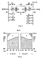
Jedes Netz ist wie in Fig. 1 gemäß Fig. 3 fest mit einem gleichbleibenden Filterkreis FK1 und FK2 für die Beseitigung von Oberschwingungen verbunden.As in FIG. 1, each network is permanently connected to a constant filter circuit FK1 and FK2 for eliminating harmonics.
Vom Betreiber werden für jedes der Netze N1, N2, N2a und N2b für die Wirkleistungen Psoll und P und die beiden Energierichtungen für stationären Betrieb zugelassene Netzspannungsgrenzen als Spannungsfenster A und nur für dynamische Vorgänge erlaubte Bereiche B entsprechend Fig. 4 sowie die zugehörigen Netzblindleistungen QN entsprechend den Tabellen Ia bis IVa vorgegeben. Aus diesen Tabellen Ia bis IVa können für günstige und ungünstige Netzbedingungen maximale und minimale, induktive bzw. kapazitive Netzblindleistungswerte entnommen werden.For each of the networks N1, N2, N2a and N2b for the active powers P soll and P and the two energy directions for steady-state operation, the operator accepts network voltage limits as voltage windows A and only areas B permitted for dynamic processes in accordance with FIG. 4 and the associated network reactive powers Q N given according to Tables Ia to IVa. From tables Ia to IVa, maximum and minimum, inductive or capacitive grid reactive power values can be found for favorable and unfavorable grid conditions.
Außerdem können aus der Summe der für die jeweils höchstzulässige Spannung des Fensters A für die einzel- nen Wirkleistungen Psoll' Pn' geteilt durch die Zahl der Wirkleistungsstufen je Energierichtung je Netz, die Mittelwerte für induktive bzw. kapazitive Netzblindleistung (unter Beachtung der Minusvorzeichen für induktive Werte) errechnet werden und für die Netze N2, N2a, N2b summiert und durch drei geteilt werden. Die jeweiligen Werte für QNLmax, Q NCmax; Q NLmittel und QNCmittel (für die Netze N2, N2a, N2b gemeinsam) sind in den Tabellen Ia bis IVa eingetragen.In addition, the sum of the ervices for each maximum permissible voltage of the window A for the individual wirkl Psoll 'P n' divided by the number of the active power levels depending energy per power direction, the mean values for inductive or capacitive Netzblindlei power (taking into account the minus sign for inductive values) can be calculated and summed for the networks N2, N2a, N 2 b and divided by three. The respective values for Q NLmax , Q NCmax ; Q NLmitttel and Q NCmittel (for networks N2, N2a, N2b together) are entered in Tables Ia to IVa.
In den Tabellen Ib,c bis IVb,c sind jeweils für die verschiedenen Netze und Energierichtungen in der HGU größte und kleinste Werte der Umrichterblindleistungen QV bei günstigen und ungünstigen Netzbedingungen eingetragen, die in weiter unten angegebener Weise berechnet werden.Tables Ib, c to IVb, c each show the largest and smallest values of the converter reactive powers Q V for the various networks and energy directions in the HGU under favorable and unfavorable network conditions, which are calculated in the manner specified below.
Bei günstigen Netzbedingungen werden die minimalen Werte QV mit der jeweils höchstzulässigen Sammelschienenspannung für die jeweilige Wirkleistung Psoll, dem zugehö- rigen Netzblindleistungsbedarf QN und allen induktiven Kompensationsmitteln L berechnet. In diesem Fall wird die Wirkung der Drosseln vom jeweiligen Netz unterstützt.Under favorable network conditions, the minimum values Q V should be the maximum permitted busbar voltage for the respective active power P, calculated to the g ehö- ring network reactive power demand Q N and all inductive compensation means L. In this case, the effect of the chokes is supported by the respective network.
Die maximalen Werte Qv werden dagegen mit der minimal zulässigen Sammelschienenspannung für die betreffende Wirkleistung PSoll (Pn), dem zugehörigen Netzblindleistungsbedarf QN und allen kapazitiven Kompensationsmitteln ermittelt.The maximum values Q v , on the other hand, are determined using the minimum permissible busbar voltage for the active power in question P Soll (P n ), the associated grid reactive power requirement Q N and all capacitive compensation means.
Bei ungüstigen Netzbedingungen wird die innere obere Grenze von QVoben jedes Netzes mit der jeweils maximal zulässigen Sammelschienenspannung bei entsprechender Wirkleistung Psoll, den zugehörigen QN und allen zugeordneten kapazitiven Kompensationsmitteln berechnet. Die innere untere Grenze QVunten jedes Netzes wird mit der jeweils minimal zulässigen Sammelschienenspannung (Fenster A) für die betreffende Wirkleistung Psoll, dem zugehörigen QN und allen vorhandenen induktiven Kompensationsmitteln berechnet.In ungüstigen network conditions, the inner upper limit of Q vtop each network is intended with the maximum permissible voltage busbar with a corresponding active power P, calculates the associated Q N and all associated capacitive compensation means. The inner lower limit Q vbottom of each network is to the minimum permissible each busbar voltage (window A) for the corresponding active power P, calculated to the associated Q N and all known inductive compensation means.
Der Netzblindleistungsbedarf QN muß von den Kondensatoren sowie den Filterkreisen FK soweit gedeckt werden, daß Qv innerhalb des Betriebsbereiches liegt.The reactive power requirement QN must be covered by the capacitors and the filter circuits FK to such an extent that Q v is within the operating range.
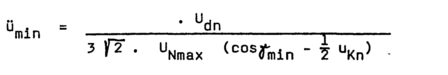
Zur Feststellung des erforderlichen minimalen und maximalen Ubersetzungsverhältnisses ü der Stufentransformatoren Tl, T2, bzw. zur Uberprüfung vorgegebener Stufentransformatoren auf ihre Anwendbarkeit (Tabelle XII) wird von der Beziehung

Die primärseitigen Ströme der Stufentransformatoren ergeben sich zu

Daraus lassen sich die erforderlichen Umrichterblindleistungen


Der Netzblindleistungsbedarf der jeweils zusammenarbeitenden beiden Netze muß soweit kompensiert werden, daß die Umrichterblindleistungen innerhalb des Betriebsbereiches liegen, d.h. daß ihre Differenz kleiner als Δ QV ist. Durch entsprechende Kombination der Stufen der beiden Stufentransformatoren kann dann ein gegenseitiges Annähern der Umrichterblindleistungen erfolgen.The N etzblindleistungsbedarf the respectively cooperating two networks must be compensated for so far that the Umrichterblindleistungen are within the operating range, that is, that their difference is smaller than Δ Q V. By appropriately combining the stages of the two stage transformers, the converter reactive powers can then be brought closer to one another.
Die Übertragung kleinster Umrichtergleichströme Id und damit die Minimierung der Ubertragungsverluste der HGU wird erreicht, wenn die Umrichterblindleistungen beider Umrichter UR1, UR2 an der unteren Grenze des jeweiligen Betriebsbereichs liegen. Die Schaltgrenzen der Kompensationsmittel sind bestimmt
Bei Stufentransformatoren mit einer
- Kurzschlußspannung UKn = 0,17
- Umrichter-Nenngleichspannung Udn = 24,4 kV
- Steuerwinkel αn = 30°
- Löschwinkel γmin = 18°
- ergeben sich QVmin =65 MVAr QVn = 115 MVAr = QVref ΔQV = 50 MVAr
- Short circuit voltage U Kn = 0.17
- Inverter -Nenn g le i chs p Annun g U dn = 24.4 kV
- Head angle α n = 30 °
- Extinguishing angle γ min = 18 °
- Q Vmin = 65 MVAr Q Vn = 115 MVAr = Q Vref ΔQ V = 50 MVAr
Aus einem Vergleich der Werte QNLmax und QNCmax sowie QNLmittel, QNCmittel für Netz N1 aus Tabelle Ia und ent-sprechende Werte für Netz N2b aus Tabelle IVa mit QV bieten sich für das Netz N1 und N2, N2a, N2b die nachfolgenden Kompensationsmitteleinheiten an.From a comparison of the values Q NLmax and Q cmax and Q NLmittel, Q NCmittel for network N1 from Table Ia and s t-speaking values for network N2b from Table IVa with Q V provide for the network N1 and N2, N2a, N2b the subsequent compensation means units.
Für Netz N1 gilt:
![]()


![]()
Eine entsprechende Überlegung für Netze N2, N2a, N2b ergeben drei Kondensatoren mit je 35 MVAr sowie eine Drossel mit 35 MVAr, d.h. für beide Netze Nl-und N2 (N2a, N2b) gilt:
C 1 = 35 MVAr, L11 und L12 je 35 MVAr;- C21' C22' C23 je 35 MVAr und L2 ebenfalls 35 MVAr.
-
C 1 = 35 MVAr, L 11 and L 12 each 35 MVAr; - C 21 ' C 22' C 23 each 35 MVAr and L 2 also 35 MVAr.
Aus den besagten Größen QFK, QN' QL' QC ergeben sich die in den Tabellen Ib,c bis IVb,c enthaltenen Werte Qv für die zugehörigen größten und kleinsten Spannungen der jeweiligen Fenster A nach der Gleichung![]()
![]()
![]()
![]()
Die errechneten Werte in Tabellen Ib,c bis IVb,c sind in den Tabellen V bis X so dargestellt, daß sich für die einzelnen Netze N1, N2; N2a, N2b gemeinsame Bereiche ergeben, aus denen gemäß Tabelle XI gemeinsame gültige Betriebsbereiche für alle Netze entnommen sind, die zeigen, daß ein erfindungsgemäß ermittelter gemeinsamer Betriebsbereich für die HGU mit Blindleistungsregelung unter Einhaltung einer ausreichenden Regelreserve bei Netzstörungen, dynamischen Vorgängen im Netz und schnellen Leistungsänderungen der Generatoren in den Netzen (Leistungsrampen) gewährleistet ist mit den verwendeten Stufentransformatoren und den gewählten Kompensationsmitteln.The calculated values in Tables Ib, c to IVb, c are shown in Tables V to X in such a way that the individual networks N1, N2; N2a, N2b result in common areas from which, according to Table XI, common valid operating areas are taken for all networks, which show that a common operating area determined according to the invention for the HGU with reactive power control while maintaining a sufficient control reserve in the event of network faults, dynamic processes in the network and rapid changes in performance of the generators in the networks (power ramps) is guaranteed with the step transformers used and the selected compensation means.
Die in der vorgenannten Tabelle XI enthaltenen Werte zeigen, daß der Betriebsbereich von 90 bis 140 MVAr mit den ermittelten Kompensationsmitteln angefahren werden kann.
- 5 Patentansprüche 4 Figuren


- 5 claims 4 figures
Claims (5)


Priority Applications (1)
| Application Number | Priority Date | Filing Date | Title |
|---|---|---|---|
| AT86109776T ATE82443T1 (en) | 1985-08-26 | 1986-07-16 | CONTROL METHOD FOR A HIGH-VOLTAGE DIRECT CURRENT TRANSMISSION CONNECTING TWO THREE-PHASE NETWORKS. |
Applications Claiming Priority (2)
| Application Number | Priority Date | Filing Date | Title |
|---|---|---|---|
| DE3530422 | 1985-08-26 | ||
| DE3530422 | 1985-08-26 |
Publications (3)
| Publication Number | Publication Date |
|---|---|
| EP0216048A2 true EP0216048A2 (en) | 1987-04-01 |
| EP0216048A3 EP0216048A3 (en) | 1989-02-22 |
| EP0216048B1 EP0216048B1 (en) | 1992-11-11 |
Family
ID=6279361
Family Applications (1)
| Application Number | Title | Priority Date | Filing Date |
|---|---|---|---|
| EP86109776A Expired - Lifetime EP0216048B1 (en) | 1985-08-26 | 1986-07-16 | Regulation method for a direct current high-voltage power transmission between two three-phase networks |
Country Status (5)
| Country | Link |
|---|---|
| US (1) | US4769751A (en) |
| EP (1) | EP0216048B1 (en) |
| AT (1) | ATE82443T1 (en) |
| CA (1) | CA1301247C (en) |
| DE (1) | DE3687104D1 (en) |
Families Citing this family (11)
| Publication number | Priority date | Publication date | Assignee | Title |
|---|---|---|---|---|
| JP3265398B2 (en) * | 1992-01-30 | 2002-03-11 | 株式会社日立製作所 | DC power transmission device control device |
| AU3944293A (en) * | 1992-04-01 | 1993-11-08 | Pennsylvania Power & Light Company | Control system and method for the parallel operation of voltage regulators |
| SE9403209L (en) * | 1994-09-23 | 1996-03-24 | Asea Brown Boveri | Series compensated inverter station |
| IT1304931B1 (en) * | 1998-12-04 | 2001-04-05 | Camillo Sansone | EQUIPMENT FOR THE CONTROL AND MANAGEMENT OF USERS POWERED BY ELECTRICITY. |
| JP4593724B2 (en) * | 2000-03-27 | 2010-12-08 | 東京エレクトロン株式会社 | Power control apparatus, power control method, and heat treatment apparatus |
| DE102005017747A1 (en) * | 2005-04-12 | 2006-10-26 | Siemens Ag | Drive for a moving along a roadway vehicle, in particular a maglev train |
| DE102008017927B4 (en) * | 2008-04-08 | 2011-12-22 | E.On Engineering Gmbh | Active star point treatment |
| WO2013178294A1 (en) | 2012-06-01 | 2013-12-05 | Abb Technology Ltd | A filter apparatus, a method for filtering harmonics in an electrical power transmission or distribution system, and such a system |
| GB2541465A (en) * | 2015-08-21 | 2017-02-22 | General Electric Technology Gmbh | Electrical assembly |
| CN110718932B (en) * | 2019-10-28 | 2022-06-10 | 东南大学 | Commutation failure prediction method considering waveform distortion and direct current change |
| CN111404188A (en) * | 2020-02-19 | 2020-07-10 | 李云亭 | Direct-current power control method for fixing transformation ratio of converter |
Citations (4)
| Publication number | Priority date | Publication date | Assignee | Title |
|---|---|---|---|---|
| DE2901263A1 (en) * | 1979-01-13 | 1980-07-24 | Bbc Brown Boveri & Cie | REGULATION OF A HGUE (HIGH VOLTAGE DIRECT CURRENT TRANSMISSION) - SHORT COUPLING |
| US4264951A (en) * | 1978-06-14 | 1981-04-28 | Hitachi, Ltd. | DC Power transmission control |
| US4330815A (en) * | 1979-05-04 | 1982-05-18 | Hitachi, Ltd. | DC Transmission control system |
| EP0067978A2 (en) * | 1981-06-10 | 1982-12-29 | Siemens Aktiengesellschaft | Method and device for regulating the network reactive power in a high voltage direct current power transmission |
Family Cites Families (5)
| Publication number | Priority date | Publication date | Assignee | Title |
|---|---|---|---|---|
| JPS54106832A (en) * | 1978-02-10 | 1979-08-22 | Hitachi Ltd | Operation control method for a/d converter |
| US4250542A (en) * | 1978-08-31 | 1981-02-10 | Bulakhov Evgeny K | Method for controlling operating conditions of D.C. transmission line and control device for effecting same |
| GB2055257A (en) * | 1979-07-27 | 1981-02-25 | Nii Postoyan Toka | Method and device for controlling a high voltage dc transmission system |
| DE3326947A1 (en) * | 1983-07-22 | 1985-02-07 | Licentia Patent-Verwaltungs-Gmbh, 6000 Frankfurt | METHOD AND CIRCUIT FOR OPERATING A HIGH VOLTAGE DC CONNECTION BETWEEN TWO AC VOLTAGE NETWORKS |
| CA1233198A (en) * | 1984-03-01 | 1988-02-23 | Helmut Neupauer | Method and apparatus to operate a high-voltage dc transmission system (hvdc) with automatic control of the converters |
-
1986
- 1986-07-16 EP EP86109776A patent/EP0216048B1/en not_active Expired - Lifetime
- 1986-07-16 AT AT86109776T patent/ATE82443T1/en not_active IP Right Cessation
- 1986-07-16 DE DE8686109776T patent/DE3687104D1/en not_active Expired - Fee Related
- 1986-08-25 CA CA000516686A patent/CA1301247C/en not_active Expired - Fee Related
- 1986-08-25 US US06/899,931 patent/US4769751A/en not_active Expired - Fee Related
Patent Citations (4)
| Publication number | Priority date | Publication date | Assignee | Title |
|---|---|---|---|---|
| US4264951A (en) * | 1978-06-14 | 1981-04-28 | Hitachi, Ltd. | DC Power transmission control |
| DE2901263A1 (en) * | 1979-01-13 | 1980-07-24 | Bbc Brown Boveri & Cie | REGULATION OF A HGUE (HIGH VOLTAGE DIRECT CURRENT TRANSMISSION) - SHORT COUPLING |
| US4330815A (en) * | 1979-05-04 | 1982-05-18 | Hitachi, Ltd. | DC Transmission control system |
| EP0067978A2 (en) * | 1981-06-10 | 1982-12-29 | Siemens Aktiengesellschaft | Method and device for regulating the network reactive power in a high voltage direct current power transmission |
Non-Patent Citations (1)
| Title |
|---|
| REVUE GENERALE DE L'ELECTRICITE vol. 42, no. 4, April 1958, PARIS FR Seite 203 - 209; S. BOICHIDZE: "Sur le réglage automatique d'une liaison à courant continu entre réseaux à courant alternatif" * |
Also Published As
| Publication number | Publication date |
|---|---|
| US4769751A (en) | 1988-09-06 |
| DE3687104D1 (en) | 1992-12-17 |
| EP0216048A3 (en) | 1989-02-22 |
| ATE82443T1 (en) | 1992-11-15 |
| CA1301247C (en) | 1992-05-19 |
| EP0216048B1 (en) | 1992-11-11 |
Similar Documents
| Publication | Publication Date | Title |
|---|---|---|
| EP0884830B1 (en) | Power supply unit with a pulse width modulated inverter, in particular for an X-ray generator | |
| DE3608704A1 (en) | VOLTAGE PEAKS OF FREE FIXED BODY SWITCH AND DEVICE FOR AUTOMATIC PERFORMANCE FACTOR CORRECTION | |
| WO2015176899A1 (en) | Power supply for a non-linear load with multilevel matrix converters | |
| EP0254911B1 (en) | Rectifier circuit and method for its controling | |
| EP0152002A1 (en) | Phase-shifter | |
| EP0216048A2 (en) | Regulation method for a direct current high-voltage power transmission between two three-phase networks | |
| EP0043146A1 (en) | Process for putting into operation one of several rectifier groups of a high-voltage direct-current transmission system connected in series | |
| DE2901263A1 (en) | REGULATION OF A HGUE (HIGH VOLTAGE DIRECT CURRENT TRANSMISSION) - SHORT COUPLING | |
| DE2605185C3 (en) | Single-phase converters | |
| EP0193039A1 (en) | Method and device for uninterrupted power supply | |
| DE102004033578A1 (en) | Device for high voltage light current transmission | |
| DE2538493C3 (en) | High-voltage direct current transmission system protected against overcurrent | |
| DE4026955C2 (en) | Converter | |
| EP0037087B1 (en) | Method and device for connecting and disconnecting without overoscillation a capacitor between two conductors of an ac network | |
| DE4036062C2 (en) | Power supply with regulated output voltage | |
| DE2433825C3 (en) | Devices for supplying energy and improving the power factor of AC networks | |
| DE2162988C3 (en) | Actuator for an AC voltage regulator | |
| EP0165898A2 (en) | Device for compensating AC network power failure | |
| DE705021C (en) | Control device for inverters working with grid-controlled steam or gas discharge paths | |
| DE19704122A1 (en) | Drive device for industrial plants, in particular for plants in the basic materials industry | |
| DE2455765B1 (en) | Torque and speed control of asynchronous machines - involves using three phase thyristor bridge network which can return power to supply when appropriate | |
| DE2418468C2 (en) | Process for controlling the converter stations of an HVDC system | |
| AT402133B (en) | Control device for supplying power to a load circuit of a DC load, and a method for operating such a control device | |
| DE733359C (en) | Arrangement for improving the operation of DC transformers consisting of an inverter and a rectifier | |
| DE2846645C2 (en) | Converter circuit |
Legal Events
| Date | Code | Title | Description |
|---|---|---|---|
| PUAI | Public reference made under article 153(3) epc to a published international application that has entered the european phase |
Free format text: ORIGINAL CODE: 0009012 |
|
| AK | Designated contracting states |
Kind code of ref document: A2 Designated state(s): AT DE FR GB IT SE |
|
| PUAL | Search report despatched |
Free format text: ORIGINAL CODE: 0009013 |
|
| AK | Designated contracting states |
Kind code of ref document: A3 Designated state(s): AT DE FR GB IT SE |
|
| 17P | Request for examination filed |
Effective date: 19890726 |
|
| 17Q | First examination report despatched |
Effective date: 19910307 |
|
| GRAA | (expected) grant |
Free format text: ORIGINAL CODE: 0009210 |
|
| AK | Designated contracting states |
Kind code of ref document: B1 Designated state(s): AT DE FR GB IT SE |
|
| PG25 | Lapsed in a contracting state [announced via postgrant information from national office to epo] |
Ref country code: IT Free format text: LAPSE BECAUSE OF FAILURE TO SUBMIT A TRANSLATION OF THE DESCRIPTION OR TO PAY THE FEE WITHIN THE PRE;WARNING: LAPSES OF ITALIAN PATENTS WITH EFFECTIVE DATE BEFORE 2007 MAY HAVE OCCURRED AT ANY TIME BEFORE 2007. THE CORRECT EFFECTIVE DATE MAY BE DIFFERENT FROM THE ONE RECORDED.SCRIBED TIME-LIMIT Effective date: 19921111 |
|
| REF | Corresponds to: |
Ref document number: 82443 Country of ref document: AT Date of ref document: 19921115 Kind code of ref document: T |
|
| REF | Corresponds to: |
Ref document number: 3687104 Country of ref document: DE Date of ref document: 19921217 |
|
| ET | Fr: translation filed | ||
| GBT | Gb: translation of ep patent filed (gb section 77(6)(a)/1977) |
Effective date: 19920205 |
|
| PLBE | No opposition filed within time limit |
Free format text: ORIGINAL CODE: 0009261 |
|
| STAA | Information on the status of an ep patent application or granted ep patent |
Free format text: STATUS: NO OPPOSITION FILED WITHIN TIME LIMIT |
|
| 26N | No opposition filed | ||
| PG25 | Lapsed in a contracting state [announced via postgrant information from national office to epo] |
Ref country code: FR Effective date: 19940331 |
|
| REG | Reference to a national code |
Ref country code: FR Ref legal event code: ST |
|
| PGFP | Annual fee paid to national office [announced via postgrant information from national office to epo] |
Ref country code: GB Payment date: 19940616 Year of fee payment: 9 |
|
| PGFP | Annual fee paid to national office [announced via postgrant information from national office to epo] |
Ref country code: AT Payment date: 19940622 Year of fee payment: 9 |
|
| PGFP | Annual fee paid to national office [announced via postgrant information from national office to epo] |
Ref country code: SE Payment date: 19940731 Year of fee payment: 9 |
|
| PGFP | Annual fee paid to national office [announced via postgrant information from national office to epo] |
Ref country code: DE Payment date: 19940915 Year of fee payment: 9 |
|
| EAL | Se: european patent in force in sweden |
Ref document number: 86109776.4 |
|
| PG25 | Lapsed in a contracting state [announced via postgrant information from national office to epo] |
Ref country code: AT Effective date: 19950716 Ref country code: GB Effective date: 19950716 |
|
| PG25 | Lapsed in a contracting state [announced via postgrant information from national office to epo] |
Ref country code: SE Effective date: 19950717 |
|
| GBPC | Gb: european patent ceased through non-payment of renewal fee |
Effective date: 19950716 |
|
| PG25 | Lapsed in a contracting state [announced via postgrant information from national office to epo] |
Ref country code: DE Effective date: 19960402 |
|
| EUG | Se: european patent has lapsed |
Ref document number: 86109776.4 |