EP0215836B1 - Automatically controlled apparatus for draining condensate from pressurized gas reservoirs - Google Patents
Automatically controlled apparatus for draining condensate from pressurized gas reservoirs Download PDFInfo
- Publication number
- EP0215836B1 EP0215836B1 EP86901479A EP86901479A EP0215836B1 EP 0215836 B1 EP0215836 B1 EP 0215836B1 EP 86901479 A EP86901479 A EP 86901479A EP 86901479 A EP86901479 A EP 86901479A EP 0215836 B1 EP0215836 B1 EP 0215836B1
- Authority
- EP
- European Patent Office
- Prior art keywords
- valve
- pipe
- chamber
- piston
- pipe fitting
- Prior art date
- Legal status (The legal status is an assumption and is not a legal conclusion. Google has not performed a legal analysis and makes no representation as to the accuracy of the status listed.)
- Expired
Links
Images


Classifications
-
- F—MECHANICAL ENGINEERING; LIGHTING; HEATING; WEAPONS; BLASTING
- F16—ENGINEERING ELEMENTS AND UNITS; GENERAL MEASURES FOR PRODUCING AND MAINTAINING EFFECTIVE FUNCTIONING OF MACHINES OR INSTALLATIONS; THERMAL INSULATION IN GENERAL
- F16T—STEAM TRAPS OR LIKE APPARATUS FOR DRAINING-OFF LIQUIDS FROM ENCLOSURES PREDOMINANTLY CONTAINING GASES OR VAPOURS
- F16T1/00—Steam traps or like apparatus for draining-off liquids from enclosures predominantly containing gases or vapours, e.g. gas lines, steam lines, containers
-
- B—PERFORMING OPERATIONS; TRANSPORTING
- B60—VEHICLES IN GENERAL
- B60T—VEHICLE BRAKE CONTROL SYSTEMS OR PARTS THEREOF; BRAKE CONTROL SYSTEMS OR PARTS THEREOF, IN GENERAL; ARRANGEMENT OF BRAKING ELEMENTS ON VEHICLES IN GENERAL; PORTABLE DEVICES FOR PREVENTING UNWANTED MOVEMENT OF VEHICLES; VEHICLE MODIFICATIONS TO FACILITATE COOLING OF BRAKES
- B60T17/00—Component parts, details, or accessories of power brake systems not covered by groups B60T8/00, B60T13/00 or B60T15/00, or presenting other characteristic features
- B60T17/002—Air treatment devices
- B60T17/004—Draining and drying devices
-
- F—MECHANICAL ENGINEERING; LIGHTING; HEATING; WEAPONS; BLASTING
- F16—ENGINEERING ELEMENTS AND UNITS; GENERAL MEASURES FOR PRODUCING AND MAINTAINING EFFECTIVE FUNCTIONING OF MACHINES OR INSTALLATIONS; THERMAL INSULATION IN GENERAL
- F16T—STEAM TRAPS OR LIKE APPARATUS FOR DRAINING-OFF LIQUIDS FROM ENCLOSURES PREDOMINANTLY CONTAINING GASES OR VAPOURS
- F16T1/00—Steam traps or like apparatus for draining-off liquids from enclosures predominantly containing gases or vapours, e.g. gas lines, steam lines, containers
- F16T1/12—Steam traps or like apparatus for draining-off liquids from enclosures predominantly containing gases or vapours, e.g. gas lines, steam lines, containers with valves controlled by excess or release of pressure
- F16T1/14—Steam traps or like apparatus for draining-off liquids from enclosures predominantly containing gases or vapours, e.g. gas lines, steam lines, containers with valves controlled by excess or release of pressure involving a piston, diaphragm, or bellows, e.g. displaceable under pressure of incoming condensate
Definitions
- This invention relates to a field of pressurized gas feeding systems, particularly compressed air feeding systems, provided with one or more air receivers and more specifically the pneumatic systems used for operating the heavy industrial vehicles.
- each air receiver of an industrial vehicle has typically more than one air receiver, e.g. there are vehicles having six or more air receivers-is provided with a manual condensate drainage apparatus, typically a snifting valve.
- the automatic condensate drainage apparatus of the present status of art available on the market are less efficient as they cause a leakage of the compressed air contained in the air receivers.
- control means operation is not automatically caused by a routine operation of the vehicle.
- GB-A-1 063 362 Another attempt is contained in GB-A-1 063 362, the subject matter of which is an automatically controlled apparatus for the condensate separation and collection, including a control means designed for being automatically operated whenever the motor of the vehicle is stopped.
- a control system is connected to said control means so as to perform at least a control stroke at any operation of the control member, a valve device being operated by said control system in order to pass from the closed to the opened position and vice versa at any stroke of said control system.
- valve members can cause only a condensate drainage for each operation, where a double drainage would be advantageous.
- this invention seeks to provide an apparatus able to cause the condensate to be drained from all air receivers of an industrial vehicle with an optimized frequency and in an automatic manner when the motor of the vehicle is stopped, which is a typical and frequency operation of the vehicle.
- Another object of the invention is to provide an apparatus causing a short opening of the valves such as to reduce the leakage of compressed air from the air receivers to that which is strictly necessary.
- Still another object of the present invention is to provide a drainage valve device particularly able to be used in the automatically controlled apparatus for the condensate drainage from the air receivers.
- the invention provides a compact, inexpensive, effective apparatus that, being connected by separate conduits to each condensate drainage outlet on the bottom of each air receiver and to an often operated member of the vehicle embodying the apparatus, causes the condensate to be drained when operating said member.
- the apparatus for the automatic condensate drainage from the air receivers essentially includes: a drainage valve device provided in each air receiver of the vehicle with the relative piping system connected to the drainage opening of the receiver a slide member operating at the same time all condensate drainage valve devices; a pneumatic double-acting cylinder and piston assembly having two chambers placed at the opposite ends of the plunger in contact with the slide member operating the drainage valve devices; a first pipe connecting a first chamber of the pneumatic assembly to a compressed air source; a second pipe connecting the second chamber of the pneumatic assembly to a compressed air source; a first two-position valve with rotatable valve member placed in the first connecting pipe; a second, two-position valve with rotatable valve member placed in the second pipe; a control means operating at the same time said first and second two-position valves and drivingly connected to the member acting on the injection pump of the motor in order to cause the latter to be stopped. It should be appreciated that the apparatus according to the invention carries out the drainage of all reservoirs wherever
- both two-position valves drivingly connected to each other are inserted in the respective pipes so that when one of them is in the position in which the compressing air flows towards the respective chamber of the pneumatic double-acting assembly, the other valve is in the opened position connected to the atmosphere, and vice versa.
- the control of the member causing the motor to be stopped allows the state of both two-position valves to be changed so as to cause a displacement of the plunger of the pneumatic double acting assembly with the consequence of a displacement of the slide member that controls, therefore, all drainage valve members to be changed from the steady closed position to the opened position, whereupon to a second transitory closed position, again to the opened position and finally to the steady closed position.
- the drainage valve device which is an object of the present application too, essentially includes: a finned cylindrical casing, a frustum-conical on-off valve member; a valve stem operating the on-off valve member and connected to the latter; a valve return spring for the valve stem; and a splined cylindrical head integral with the frustum-conical valve member.
- the splined cylindrical head integral with the frustum-conical valve member is placed in the chamber of the valve casing connected to the air receiver from which the condensate has to be drained and consequently said head is exposed to the latter.
- Such cylindrical head has a circular outer face and an inner face in form of a circular corona, the area of which is much smaller than the outer face, at the connection with the frustum-conical valve member so that, owing to the splines the air pressure acts on opposite surfaces having very different area as described into detail afterwards.
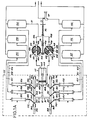
- the apparatus essentially includes: six condensate drainage valve members preferably arranged on two rows of three valve members each generally designated by 10A-10F and connected each to the drainage opening of the respective reservoir 11A-11 by means of a piping system 12A-12F, respectively; a H-shaped slide member operating at the same time the valve members 10A-10F and generally designated by 30; a pneumatic double-acting cylinder and piston assembly 40; a first pipe 50A feeding comprssed air to a first chamber of the pneumatic assembly; a second pipe 50B feeding compressed air to the second chamber of the pneumatic assembly; a first two-position valve 60A placed in the pipe 50A; a second two-position valve 60B placed in the pipe 50B; and a control member designated by 70 and operating at the same time both two-position valves.
- valve members 10A-10F, the slide member 30 and the pneumatic assembly 40 are preferably arranged in the same casing CE designated by the dashed line in the Figures 1A and 1B.
- the essential feature of the apparatus of the invention is to drain the condensate in very short time in order to avoid the loss of large amounts of compressed air from the reservoirs. That being stated, the valve member 10A-10F have been designed to accomplish this object and each of them has the embodiment illustrated in the Figures 3 and 4.
- each valve member generally designated by the numeral 10 includes: a cylindrical casing having two chambers 14A and 14B separated by a centrally opened partition 13 and closed by a cover 15A and 15B, respectively; a piston 16 provided with a collar 18 having a flattened end 19 at the outer side of the cover 15A and an inner, axially splined end 20, said piston being slideable into the bores of the cover 15A and the partition 13; a valve spring 21 arranged on the piston 16 and acting as a compression spring between the collar 18 and the partition 13; a valve seat 22 formed in the chamber 14B; a ball valve member 23 placed in the chamber 14B so as to seal the valve seat 22; a spring 24 acting as a compression spring between the ball valve member 23 and the inner face of the cover 15B; a pipe fitting 25 integral with the cover 15B and a drainage branch pipe open to the atmosphere.
- valve seat 22 divides the chamber 14B into an inner space 27A communicating with the atmosphere through the branch pipe 26 and in which the end 20 of the piston 16 is arranged, and an outer space 27B communicating with the pipe 12 through the pipe fitting 25 and then with the respective air receiver 11, in which space the ball valve member 23 and the spring 24 are arranged.
- the piston 16 can sealingly slide into the central bore of the partition 13.
- the slide member 30 operating the valve members 10A-10F is arranged between two rows of the latter and consists of a H-shaped frame having two arms 31A, 31B parallel to each other and a central traverse 32.
- the one ends 33A-33C of three link rods 34A-34C are linked with the arm 31A, while the other ends 35A-35C are linked with the ends 19A-19C of the pistons of the relative condensate drainage valve members 10A-10C, respectively.
- the three link rods 34D-34F of the arm 31B are linked with the ends 19D-19F of the pistons of the relative condensate drainage valve members 10D-10F, respectively.
- the H-shaped slide member 30 guided in two pairs of fixed guide members 36A, 36B is restrained to more only in an axial direction with respect to the casing CE since the cross movements thereof are prevented.
- the end 41 of the piston 42 of the pneumatic double-acting cylinder and piston assembly 40 is connected to the central transverse 32.
- Such pneumatic assembly 40 further includes a cylindrical casing 43 in which the plunger 44 dividing as well known in the inner cavity of the cylinder into two chambers 45A and 45B is sealingly slideable.
- the chamber 45A has a pipe fitting 46A for the supply of compressed air as well as the chamber 45B has a similar pipe fitting designated by 46B.
- the pipe fitting 46A is connected through the pipe 50A to the first two-position valve 60A and the pipe fitting 46B is connected through the pipe 50B to the second two-position valve 60B.
- the pipes 50A and 50B are supplied with compressed air from one of the air receivers 11A-11F and in the present case from the air receiver 11A through the pipe 51.
- Both valves 60A, 60B of well known type have the same structure and include each a hollow cylindrical casing 61A, 61B having first and second pipe fittings 62A, 62B and 63A, 63B, respectively connected to the outside and diametrally opposite each other, and a third pipe fitting 64A, 64B connected to the outside and arranged at an angular displacement from the first pipe fitting 62A, 62B.
- a solid cylindrical body 65A, 65B placed within the casing 61A, 61B is provided with a diametral passageway 66A, 66B at one end of which a chamber 67A, 67B is provided having an angular amplitude equal to the angle between the pipe fittings 62A, 62B and 64A, 64B, respectively.
- Each solid cylindrical body 65A, 65B can move within the respective hollow cylindrical casing 61A, 61 B by an angular displacement equal to the amplitude of the chamber 67A, 67B, respectively, this movement being controlled from the outside.
- both solid cylindrical bodies 65A, 65B of the valves 60A, 60B are driven by one shaft 68. Furthermore, the two-position valves 60A, 60B are arranged so that when the diametral passageway 66A of the solid cylindrical body 65A connects the pipe fittings 62A and 63A to each other, the diametral passageway 66B of the other solid cylindrical body 65B is turned with respect to the position of the former, and vice versa.
- the chambers 67A and 67B connect the adjacent pipe fittings 62A, 64A and 62B, 64B, respectively, when the diametral passageway 66A and 66B are turned with respect to the position in which they connect the pipe fittings 62A, 64B to the pipe fittings 63A, 63B, respectively.
- the control shaft 68 of the rotating bodies 65A, 65B is integral with a lever arm 69, at the other end of which the free end of a piston 71 operated by a member 70 controlling at the same time both valves 60A, 60B is connected.
- control member 70 is consisting of the pneumatic cylinder and piston assembly that in a well known manner controls in the most of heavy vehicles the turning off of the motor acting on the rackwork of the injection pump.
- control member can consist of any other pneumatic, electric, electromagnetic, hydraulic or mechanic control member which can perform the same function of the control member 70 described herein.
- the chamber 45B is connected to the atmosphere through the left length of the pipe 50B the pipe fitting 62B, the chamber 67B and the pipe fitting 64B.
- the plunger 44 moves rightwards in the figure trailing in the same direction the stem of the piston 42 and the slide member 30.
- each turning off of the vehicle motor will cause a double-acting drainage of the condensate from all air receivers 11A-11F.
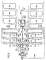
- FIG. 5 it is illustrated a second embodiment of the invention, in which the construction formed of the pneumatic double-acting cylinder and piston assembly 40 and both valves 60A, 60B is replaced by two bellow chambers 140A, 140B having control members with different diameters.
- each bellow chamber 140A, 140B includes an outer casing 143A, 143B, which is provided with a pipe fitting 146A, 146B for the supplying of the compressed air and within which a control member 144A, 144B is movable together with a bellow 148A, 148B, the latter being connected at one end to the former and at the second end to the bottom 149A, 149B of the respective chamber 140A, 140B.
- control members 144A, 144B, the slide member 130 and all the other components of the apparatus are in the positions illustrated by dashed lines, as the compressed air from the air receiver 111D through the pipe 160B acts on the inner surface of the control member 144B.
- the stop of the motor will cause the pneumatic valve VP to be operated and to convey compressed air through the pipe 160A and the pipe fitting 146A within the bellow 148A which will expand and push the control member 144A leftwards in Figure 5.
- the piston stem 142, the traverse 132 and the slide member 130 will move with the control member 144A. This displacement will cause the movement of the link rods 134A-134F as already described with the consequent on-off of the valve member 110A-110F.
- the displacement of the slide member 30 can be provided by means of different control members of electric, electromagnetic, mechanic, hydraulic type without departing from the scope of the invention.
- each cylindrical casing 210 has one side a closed chamber 214B and a cover 215B and on the other side a cylindrical cavity 214A counterbored at its end 215A; a valve stem 216 provided with a collar 218 having a flattened end 219 outside the end 215A of the casing 210 and an inner end 220 connected to a frustum-conical valve member 223, said stem 216 being slideable in the cavity 214A; a spring 221 arranged on the stem 216 and acting as a compression spring between the collar 218 and the bottom 213 of the counterbore 215A; a valve seat 222 formed in the chamber 214B; a frustum-conical valve member 223 arranged in the chamber 214B so as to seal the valve seat 222; a pipe fitting 225 integral with the cover 215B and a branch pipe 226 open to the atmosphere.
- valve seat 222 divides the chamber 214B into an inner portion 227A connected to the atmosphere through the branch pipe 226, in which the end 220 of the stem 216 is received, and an outer portion 227B connected through the pipe fitting 225 to the pipe 212 and then to the respective air receiver 11, in which portion 227B both the valve member 223 and the cylindrical head 224 are received.
- the surface of the cylindrical head 224 has splines 224B causing the air pressure from the pipe 212 to act besides on the circular head 260 also on the annular surface 261 surrounding the frustum-conical valve member 223. With such an arrangement the force on the circular head 260 is partially compensated by that on the annular surface 261.
- the slide member 230 controlling the valve members is arranged between the two rows of the latter and is formed of a frame 231 linked to one end 233 of the link rod 234, the other end 235 of which is linked to the end 219 of the stem 216 of the condensate drainage valve device 210. It is important to be noted that the link between the end 235 and the flattened end 219 is carried out by means of a pin 235C received into a slot 235D of the end 219, thus forming a clearance which will avoid the necessity of a strict tolerance of manufacturing of the single components. As all parts described and illustrated herein are of the same structure, arrangement and operation as described above, the operation of the valve device will be briefly described herebelow.
- the forward stroke (arrow F,) of the slide member 231 in the axial direction will cause through the link rod 234 moving from the oblique position A of Figure 6 to the perpendicular direction B of Figure 7, a reciprocating motion of the stem 216 so that the valve member 223 will move away from the valve seat 222, thus allowing the outlet of the condensate into the atmosphere through the branch pipe 226.
- the valve member 223 will seal then the valve seat 222 when the link rod 234 moves to the position C.
- the valve member 223 will open during the return stroke (arrow F 2 ) of the slide member 231 when the link rod 234 moves to the position B and will then close steadily (position A held up to the new operation) at the end of such a return stroke.
- valve stem 216 and then of the valve member 223, are made very smooth and are cushioned by the action of the compressed air on the annular face 261 besides being promoted by the spring 221.
- Such feature avoids any troublesome striking noise of the valve member 223 against the valve seat 222.
- an inserted valve seat could be used, as shown in the figures, for example made of either, a different metal than that of the valve casing or of a plastic material.
- the two lengths of the cylindrical valve casing separated by the branch pipe 226 are finned, as designated by 262, in order to dissipate the heat more quickly.
Abstract
Description
- This invention relates to a field of pressurized gas feeding systems, particularly compressed air feeding systems, provided with one or more air receivers and more specifically the pneumatic systems used for operating the heavy industrial vehicles.
- As well known, a considerable amount of water produced by condensation of the humidity always present in the atmospheric air deposits on the bottom of the air receivers. Such water deposit in undesirable as it may cause even very serious damages both to the containing receivers and the compressed air utilizing systems. For instance, the water on the bottom of the reservoir can cause the oxidation and then the corrosion of the reservoir walls to be initiated. Furthermore, the water can be entrained into the conduits in which it may freeze in case of a low outer temperature, thus causing the conduits to be occluded and broken with the tragic event which may result when said conduits are connected to the braking system of a heavy vehicle. It follows that the drainage of the water deposit from the air receivers, which is very expedient in case of stationary compressed air systems, becomes an absolute necessity in case of systems destined to heavy vehicles and mainly in case of braking systems. Unfortunately there is at the time being no efficient device carrying out automatically and with the desired frequency the drainage of the condensate deposits existing in the air receivers of the industrial vehicles. In most cases, however, each air receiver of an industrial vehicle-it should be noted that each heavy vehicle has typically more than one air receiver, e.g. there are vehicles having six or more air receivers-is provided with a manual condensate drainage apparatus, typically a snifting valve. This rather primitive solution, which is not able for certain by itself to assure that the necessary drainage of the condensate deposits is carried out with the due reliability, is further impaired by the placement of the various air receivers under the frame of the vehicle in hardly accessible positions. It follows that the manual condensate drainage operation is usually carried out only in case the vehicle is stopped for repair or maintenance reasons.
- Therefore, the gravity of the danger inherent to the lack of a periodic and frequent condensate drainage of the air receivers, which the heavy vehicles are equipped with, caused such vehicles to be necessarily provided with an automatic apparatus providing for such an operation. It should be noted that, since the condensate drainage causes necessarily the outlet of compressed air, the operation of such an automatic apparatus has to provide for the opening of the valve devices being limited to the time strictly necessary for the drainage of the condensate in order to avoid the total leakage of the compressed air contained in the air receiver or most of it.
- Failing this feature, i.e. the possibility of causing a very short opening of the condensate drainage valve in order to avoid the loss of compressed air from the air receiver, the automatic condensate drainage apparatus of the present status of art available on the market are less efficient as they cause a leakage of the compressed air contained in the air receivers.
- Some attempts have been made in order to solve this problem as in the closest prior art represented by DE-A-1 580 111, wherein an automatically controlled apparatus for draining the condensate from the pressurized gas reservoirs according to the first part of
Claim 1 is shown. - The drawback of this apparatus is that the control means operation is not automatically caused by a routine operation of the vehicle.
- Another attempt is contained in GB-A-1 063 362, the subject matter of which is an automatically controlled apparatus for the condensate separation and collection, including a control means designed for being automatically operated whenever the motor of the vehicle is stopped. A control system is connected to said control means so as to perform at least a control stroke at any operation of the control member, a valve device being operated by said control system in order to pass from the closed to the opened position and vice versa at any stroke of said control system.
- However the construction of the valve members can cause only a condensate drainage for each operation, where a double drainage would be advantageous.
- Therefore, this invention seeks to provide an apparatus able to cause the condensate to be drained from all air receivers of an industrial vehicle with an optimized frequency and in an automatic manner when the motor of the vehicle is stopped, which is a typical and frequency operation of the vehicle.
- Another object of the invention is to provide an apparatus causing a short opening of the valves such as to reduce the leakage of compressed air from the air receivers to that which is strictly necessary.
- Still another object of the present invention is to provide a drainage valve device particularly able to be used in the automatically controlled apparatus for the condensate drainage from the air receivers.
- To accomplish the proposed objects the invention provides a compact, inexpensive, effective apparatus that, being connected by separate conduits to each condensate drainage outlet on the bottom of each air receiver and to an often operated member of the vehicle embodying the apparatus, causes the condensate to be drained when operating said member.
- More exactly, it is described and illustrated an embodiment of the apparatus which is connected to the member that almost in the whole of the industrial vehicles controls the stop of the motor by acting on the injection pump.
- The apparatus for the automatic condensate drainage from the air receivers according to a preferred embodiment essentially includes: a drainage valve device provided in each air receiver of the vehicle with the relative piping system connected to the drainage opening of the receiver a slide member operating at the same time all condensate drainage valve devices; a pneumatic double-acting cylinder and piston assembly having two chambers placed at the opposite ends of the plunger in contact with the slide member operating the drainage valve devices; a first pipe connecting a first chamber of the pneumatic assembly to a compressed air source; a second pipe connecting the second chamber of the pneumatic assembly to a compressed air source; a first two-position valve with rotatable valve member placed in the first connecting pipe; a second, two-position valve with rotatable valve member placed in the second pipe; a control means operating at the same time said first and second two-position valves and drivingly connected to the member acting on the injection pump of the motor in order to cause the latter to be stopped. It should be appreciated that the apparatus according to the invention carries out the drainage of all reservoirs wherever the various air receivers are placed in the vehicle as it will be apparent from the following detailed description.
- Furthermore, it should be noted that both two-position valves drivingly connected to each other are inserted in the respective pipes so that when one of them is in the position in which the compressing air flows towards the respective chamber of the pneumatic double-acting assembly, the other valve is in the opened position connected to the atmosphere, and vice versa. In operation, the control of the member causing the motor to be stopped allows the state of both two-position valves to be changed so as to cause a displacement of the plunger of the pneumatic double acting assembly with the consequence of a displacement of the slide member that controls, therefore, all drainage valve members to be changed from the steady closed position to the opened position, whereupon to a second transitory closed position, again to the opened position and finally to the steady closed position.
- The drainage valve device, which is an object of the present application too, essentially includes: a finned cylindrical casing, a frustum-conical on-off valve member; a valve stem operating the on-off valve member and connected to the latter; a valve return spring for the valve stem; and a splined cylindrical head integral with the frustum-conical valve member.
- The splined cylindrical head integral with the frustum-conical valve member is placed in the chamber of the valve casing connected to the air receiver from which the condensate has to be drained and consequently said head is exposed to the latter.
- Such cylindrical head, however, has a circular outer face and an inner face in form of a circular corona, the area of which is much smaller than the outer face, at the connection with the frustum-conical valve member so that, owing to the splines the air pressure acts on opposite surfaces having very different area as described into detail afterwards.
- An embodiment and the operation of the apparatus according to the invention will be more readily apparent from the following description with reference to the accompanying drawings, in which:
- Figure 1A is a general schematic view of the apparatus placed in an industrial vehicle having six air receivers, the apparatus being in the steady closed position;
- Figure 1B is a similar view with the apparatus being in the transitory closed position;
- Figure 2 is a perspective, fragmentary view showing in enlarged scale both two-position valves and the control member;
- Figure 3 is an axial, fragmentary section showing an enlarged scale one of the condensate drainage valve members in the closed position;
- Figure 4 is a similar view with the condensate drainage valve members in the opened position; and
- Figure 5 is a view similar to the Figures 1A and 1B of a second embodiment of the apparatus;
- Figure 6 is an axial section of the condensate drainage valve device in the closed position; and
- Figure 7 is a section of the valve device in the opened position.
- Referring particularly to the Figures 1A and 1B the apparatus according to the invention essentially includes: six condensate drainage valve members preferably arranged on two rows of three valve members each generally designated by 10A-10F and connected each to the drainage opening of the respective reservoir 11A-11 by means of a
piping system 12A-12F, respectively; a H-shaped slide member operating at the same time thevalve members 10A-10F and generally designated by 30; a pneumatic double-acting cylinder andpiston assembly 40; afirst pipe 50A feeding comprssed air to a first chamber of the pneumatic assembly; asecond pipe 50B feeding compressed air to the second chamber of the pneumatic assembly; a first two-position valve 60A placed in thepipe 50A; a second two-position valve 60B placed in thepipe 50B; and a control member designated by 70 and operating at the same time both two-position valves. - It should be noted that the six
valve members 10A-10F, theslide member 30 and thepneumatic assembly 40 are preferably arranged in the same casing CE designated by the dashed line in the Figures 1A and 1B. - The essential feature of the apparatus of the invention is to drain the condensate in very short time in order to avoid the loss of large amounts of compressed air from the reservoirs. That being stated, the
valve member 10A-10F have been designed to accomplish this object and each of them has the embodiment illustrated in the Figures 3 and 4. - As a matter of fact each valve member generally designated by the
numeral 10 includes: a cylindrical casing having twochambers 14A and 14B separated by a centrally openedpartition 13 and closed by acover 15A and 15B, respectively; apiston 16 provided with acollar 18 having aflattened end 19 at the outer side of thecover 15A and an inner, axiallysplined end 20, said piston being slideable into the bores of thecover 15A and thepartition 13; avalve spring 21 arranged on thepiston 16 and acting as a compression spring between thecollar 18 and thepartition 13; avalve seat 22 formed in the chamber 14B; aball valve member 23 placed in the chamber 14B so as to seal thevalve seat 22; aspring 24 acting as a compression spring between theball valve member 23 and the inner face of the cover 15B; a pipe fitting 25 integral with the cover 15B and a drainage branch pipe open to the atmosphere. As clearly illustrated, thevalve seat 22 divides the chamber 14B into aninner space 27A communicating with the atmosphere through thebranch pipe 26 and in which theend 20 of thepiston 16 is arranged, and anouter space 27B communicating with thepipe 12 through the pipe fitting 25 and then with therespective air receiver 11, in which space theball valve member 23 and thespring 24 are arranged. - It is useful to note that the
piston 16 can sealingly slide into the central bore of thepartition 13. Turning now to the Figures 1A and1Bthe slide member 30 operating thevalve members 10A-10F is arranged between two rows of the latter and consists of a H-shaped frame having twoarms central traverse 32. - The one ends 33A-33C of three
link rods 34A-34C are linked with thearm 31A, while the other ends 35A-35C are linked with theends 19A-19C of the pistons of the relative condensatedrainage valve members 10A-10C, respectively. - Likewise, the three link rods 34D-34F of the
arm 31B are linked with theends 19D-19F of the pistons of the relative condensate drainage valve members 10D-10F, respectively. - Further, the H-
shaped slide member 30 guided in two pairs offixed guide members end 41 of thepiston 42 of the pneumatic double-acting cylinder andpiston assembly 40 is connected to the central transverse 32. - Such
pneumatic assembly 40 further includes a cylindrical casing 43 in which theplunger 44 dividing as well known in the inner cavity of the cylinder into twochambers chamber 45A has apipe fitting 46A for the supply of compressed air as well as thechamber 45B has a similar pipe fitting designated by 46B. - As mentioned above the
pipe fitting 46A is connected through thepipe 50A to the first two-position valve 60A and thepipe fitting 46B is connected through thepipe 50B to the second two-position valve 60B. As clearly illustrated in the Figures 1A and 1B thepipes pipe 51. Bothvalves cylindrical casing second pipe fittings - A solid
cylindrical body casing diametral passageway chamber 67A, 67B is provided having an angular amplitude equal to the angle between thepipe fittings - Each solid
cylindrical body cylindrical casing chamber 67A, 67B, respectively, this movement being controlled from the outside. - As better illustrated in Figure 2, both solid
cylindrical bodies valves shaft 68. Furthermore, the two-position valves diametral passageway 66A of the solidcylindrical body 65A connects thepipe fittings diametral passageway 66B of the other solidcylindrical body 65B is turned with respect to the position of the former, and vice versa. - Therefore, as clearly illustrated, the
chambers 67A and 67B, connect theadjacent pipe fittings diametral passageway pipe fittings pipe fittings - The
control shaft 68 of therotating bodies lever arm 69, at the other end of which the free end of apiston 71 operated by amember 70 controlling at the same time bothvalves - In the embodiment of the invention herein illustrated and described, the
control member 70 is consisting of the pneumatic cylinder and piston assembly that in a well known manner controls in the most of heavy vehicles the turning off of the motor acting on the rackwork of the injection pump. - It is to be intended, however, as repeated afterwards, that such control member can consist of any other pneumatic, electric, electromagnetic, hydraulic or mechanic control member which can perform the same function of the
control member 70 described herein. - The operation of the apparatus according to the invention is as follows:
- Under normal running conditions of the vehicle the
control member 70 is in the position of Figure 1A, in which it is resiliently urged, for example, by the spring ML. Consequently, all members of the apparatus are in the position illustrated in the above mentioned figure. More particularly, the compressed air of the receiver 11A, that reaches thechamber 45A of the pneumatic double-actingassembly 40 through thepipes diametral passageway 66A connecting in the through position thepipe fittings plunger 44 and the slide member as well in their shifted positions on the extreme left in Figure 1A. - It is to be noted that due to the position of the solid
cylindrical body 658 thechamber 45B is connected to the atmosphere through the left length of thepipe 50B the pipe fitting 62B, the chamber 67B and the pipe fitting 64B. - The operation of the
pneumatic assembly 70, initiated as it is known by the opening of the pneumatic valve VP through the pipe TT (Figure 2) in order to turn off the motor of the vehicle, will cause a stroke to the right of thepiston 71 of the assembly 70 (Figures 1B and 2) and then a rotation in the clockwise direction of the solidcylindrical bodies shaft 68 to the position illustrated in Figure 2. - Consequently, the compressed air of the receiver 11A raises the pressure of the
chamber 45B of theslide member 40 through thepipe 51 and the whole length of thepipe 50B owing to the position held by thediametral passageway 66B connecting now thepipe fittings - Since the
chamber 45A is at the atmospheric pressure as the compressed air is blown off in the atmosphere through the left length of thepipe 50A, the pipe fitting 62A, thechamber 67A and the pipe fitting 64A, theplunger 44 moves rightwards in the figure trailing in the same direction the stem of thepiston 42 and theslide member 30. - The rightward movement of the
slide member 30 causes the movement of thelink rods 34A-34C and 34D-34F from the position inclined with respect to the axis of therespective arms ball valve member 23 is pressed against thevalve seat 22 so as to seal the passageway between thechamber 27B and thechamber 27A, to the position of Figure 4, in which thehead 20 of the piston pushes theball 23 to move away from theseat 22 against thespring 24. Therefore, the condensate on the bottom of the air receivers 11A-11 F and in thepipes 12A-12F is quickly expelled into the atmosphere through thechamber 27B, thechamber 27A and thebranch pipe 26. It should be appreciated that the opening time of the assembly of theball valve member 23 and theseat 22 is rather short as the continuation of the stroke of theslide member 30 rightwards causes the latter (and then thelink rods 34A-34F) to move to the position illustrated with dashed lines in Figure 1B, in which theseats 22 are sealed again from theballs 23 because of the retraction of the pistons 16A―11 F. - At this moment, in the typical operation of the diesel engine the
pneumatic assembly 70 is moved again by return spring ML to the position taken during the normal running of the vehicle. This will involve a back stroke leftwards of theslide member 30 with the consequence of a transitory opening of the assembly 23-22 when thelink rods 34A-34F move to the positions of the Figures 1B and 4, and an immediate closure when they come back to the positions illustrated in the Figures 1A and 3. - Therefore, each turning off of the vehicle motor will cause a double-acting drainage of the condensate from all air receivers 11A-11F.
- In Figure 5 it is illustrated a second embodiment of the invention, in which the construction formed of the pneumatic double-acting cylinder and
piston assembly 40 and bothvalves - As well known by itself each bellow chamber 140A, 140B includes an outer casing 143A, 143B, which is provided with a pipe fitting 146A, 146B for the supplying of the compressed air and within which a
control member - For the operation of this embodiment it is sufficient to mention that under normal running conditions of the vehicle, the
control members slide member 130 and all the other components of the apparatus are in the positions illustrated by dashed lines, as the compressed air from the air receiver 111D through the pipe 160B acts on the inner surface of thecontrol member 144B. The stop of the motor will cause the pneumatic valve VP to be operated and to convey compressed air through thepipe 160A and the pipe fitting 146A within the bellow 148A which will expand and push thecontrol member 144A leftwards in Figure 5. Also thepiston stem 142, thetraverse 132 and theslide member 130 will move with thecontrol member 144A. This displacement will cause the movement of the link rods 134A-134F as already described with the consequent on-off of thevalve member 110A-110F. - As it will be apparent to the skilled in the art the displacement of the
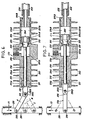
slide member 30 can be provided by means of different control members of electric, electromagnetic, mechanic, hydraulic type without departing from the scope of the invention. - In the Figures 6 and 7 parts of the valve device equal or similar to those shown in the foregoing Figures 1A to 5 are designated by the same reference numerals increased by 200.
- As clearly illustrated each
cylindrical casing 210 has one side aclosed chamber 214B and acover 215B and on the other side acylindrical cavity 214A counterbored at itsend 215A; avalve stem 216 provided with acollar 218 having a flattenedend 219 outside theend 215A of thecasing 210 and aninner end 220 connected to a frustum-conical valve member 223, saidstem 216 being slideable in thecavity 214A; aspring 221 arranged on thestem 216 and acting as a compression spring between thecollar 218 and thebottom 213 of thecounterbore 215A; avalve seat 222 formed in thechamber 214B; a frustum-conical valve member 223 arranged in thechamber 214B so as to seal thevalve seat 222; a pipe fitting 225 integral with thecover 215B and abranch pipe 226 open to the atmosphere. - As clearly illustrated, the
valve seat 222 divides thechamber 214B into aninner portion 227A connected to the atmosphere through thebranch pipe 226, in which theend 220 of thestem 216 is received, and an outer portion 227B connected through the pipe fitting 225 to thepipe 212 and then to therespective air receiver 11, in which portion 227B both thevalve member 223 and thecylindrical head 224 are received. - The surface of the
cylindrical head 224 hassplines 224B causing the air pressure from thepipe 212 to act besides on thecircular head 260 also on theannular surface 261 surrounding the frustum-conical valve member 223. With such an arrangement the force on thecircular head 260 is partially compensated by that on theannular surface 261. - Likewise to what already illustrated and described above the slide member 230 controlling the valve members is arranged between the two rows of the latter and is formed of a
frame 231 linked to oneend 233 of thelink rod 234, theother end 235 of which is linked to theend 219 of thestem 216 of the condensatedrainage valve device 210. It is important to be noted that the link between theend 235 and the flattenedend 219 is carried out by means of apin 235C received into aslot 235D of theend 219, thus forming a clearance which will avoid the necessity of a strict tolerance of manufacturing of the single components. As all parts described and illustrated herein are of the same structure, arrangement and operation as described above, the operation of the valve device will be briefly described herebelow. - The forward stroke (arrow F,) of the
slide member 231 in the axial direction will cause through thelink rod 234 moving from the oblique position A of Figure 6 to the perpendicular direction B of Figure 7, a reciprocating motion of thestem 216 so that thevalve member 223 will move away from thevalve seat 222, thus allowing the outlet of the condensate into the atmosphere through thebranch pipe 226. Thevalve member 223 will seal then thevalve seat 222 when thelink rod 234 moves to the position C. Likewise thevalve member 223 will open during the return stroke (arrow F2) of theslide member 231 when thelink rod 234 moves to the position B and will then close steadily (position A held up to the new operation) at the end of such a return stroke. - It should be appreciated that the movements of the
valve stem 216, and then of thevalve member 223, are made very smooth and are cushioned by the action of the compressed air on theannular face 261 besides being promoted by thespring 221. Such feature avoids any troublesome striking noise of thevalve member 223 against thevalve seat 222. To this end an inserted valve seat could be used, as shown in the figures, for example made of either, a different metal than that of the valve casing or of a plastic material. - As it is evident in the figures, the two lengths of the cylindrical valve casing separated by the
branch pipe 226 are finned, as designated by 262, in order to dissipate the heat more quickly. - From what above it is clear that the present invention fully accomplishes the above mentioned objects.
Claims (20)
Priority Applications (1)
| Application Number | Priority Date | Filing Date | Title |
|---|---|---|---|
| AT86901479T ATE58784T1 (en) | 1985-02-26 | 1986-02-25 | AUTOMATICALLY CONTROLLED CONDENSATE SEPARATOR FOR COMPRESSED GAS TANKS. |
Applications Claiming Priority (2)
| Application Number | Priority Date | Filing Date | Title |
|---|---|---|---|
| IT4773285 | 1985-02-26 | ||
| IT47732/85A IT1182711B (en) | 1985-02-26 | 1985-02-26 | PERFECTED DISCHARGE VALVE DEVICE FOR CONDENSATION DISCHARGE SYSTEMS FROM COMPRESSED AIR TANKS |
Publications (2)
| Publication Number | Publication Date |
|---|---|
| EP0215836A1 EP0215836A1 (en) | 1987-04-01 |
| EP0215836B1 true EP0215836B1 (en) | 1990-11-28 |
Family
ID=11262161
Family Applications (1)
| Application Number | Title | Priority Date | Filing Date |
|---|---|---|---|
| EP86901479A Expired EP0215836B1 (en) | 1985-02-26 | 1986-02-25 | Automatically controlled apparatus for draining condensate from pressurized gas reservoirs |
Country Status (6)
| Country | Link |
|---|---|
| EP (1) | EP0215836B1 (en) |
| JP (1) | JPS63500733A (en) |
| AU (1) | AU5542686A (en) |
| DE (1) | DE3675863D1 (en) |
| IT (1) | IT1182711B (en) |
| WO (1) | WO1986004976A1 (en) |
Family Cites Families (5)
| Publication number | Priority date | Publication date | Assignee | Title |
|---|---|---|---|---|
| GB690862A (en) * | 1949-07-22 | 1953-04-29 | Carl Otto Bruestle | Improvements in moisture ejector valve for a pressure fluid, that is air pressure, system |
| CH400433A (en) * | 1963-02-21 | 1965-10-15 | Magneti Marelli Spa | Device for automatically operating the exhaust valve in compressed air purifiers for pneumatic systems installed on motor vehicles |
| US3282293A (en) * | 1963-05-23 | 1966-11-01 | Lloyd D Barger | Means for exiting a fluid from a compartment |
| DE1580111B2 (en) * | 1966-11-11 | 1976-04-22 | Knorr-Bremse GmbH, 8000 München | DRAINAGE DEVICE FOR COMPRESSED AIR BRAKING SYSTEMS OF MOTOR VEHICLES |
| FR2082631A5 (en) * | 1970-03-20 | 1971-12-10 | Gen Pneumatic |
-
1985
- 1985-02-26 IT IT47732/85A patent/IT1182711B/en active
-
1986
- 1986-02-25 EP EP86901479A patent/EP0215836B1/en not_active Expired
- 1986-02-25 DE DE8686901479T patent/DE3675863D1/en not_active Expired - Lifetime
- 1986-02-25 JP JP61501434A patent/JPS63500733A/en active Pending
- 1986-02-25 AU AU55426/86A patent/AU5542686A/en not_active Abandoned
- 1986-02-25 WO PCT/IT1986/000015 patent/WO1986004976A1/en active IP Right Grant
Also Published As
| Publication number | Publication date |
|---|---|
| IT8547732A1 (en) | 1986-08-26 |
| WO1986004976A1 (en) | 1986-08-28 |
| IT1182711B (en) | 1987-10-05 |
| DE3675863D1 (en) | 1991-01-10 |
| EP0215836A1 (en) | 1987-04-01 |
| AU5542686A (en) | 1986-09-10 |
| JPS63500733A (en) | 1988-03-17 |
| IT8547732A0 (en) | 1985-02-26 |
Similar Documents
| Publication | Publication Date | Title |
|---|---|---|
| CA1267126A (en) | Expanding gate valve with pneumatic actuator | |
| EP1313948B1 (en) | Reciprocating motor with unidirectional fluid flow | |
| CA1272426A (en) | Combined linear hydraulic motor and transfer valve | |
| AU623069B2 (en) | Four-way slide valve | |
| US6220566B1 (en) | Incrementally positionable ball valve | |
| EP0803651A1 (en) | Fluid-controlled actuator assembly | |
| EP0215836B1 (en) | Automatically controlled apparatus for draining condensate from pressurized gas reservoirs | |
| US6431046B1 (en) | Pneumatic motor | |
| JP2005518508A (en) | Vane spool type directional control valve and four-way control valve for refrigeration cycle using the same | |
| EP0927846B1 (en) | A four-way selector valve | |
| US4930403A (en) | Directionally controlled hydraulic cylinder | |
| JPH06159140A (en) | Pneumatic type linear type driving device with terminal-position locking device | |
| CA2464841A1 (en) | Compressor with swash plate housing inlet port | |
| EP0996826B1 (en) | Hydraulic fluid actuator with metal to metal seals | |
| US3037525A (en) | Four-way changeover valve | |
| KR20010091920A (en) | High-pressure ball-poppet control valve | |
| SU1258512A1 (en) | Divider for moving in pipeline | |
| SU1789813A1 (en) | Ball cock | |
| AU2022211870B2 (en) | A pinch valve assembly | |
| US3112654A (en) | Self-locking fluid operated valve actuating mechanism | |
| EP0202198A1 (en) | Large-sized on-off valve of high throughput, particularly for vacuum systems and nuclear fusion installations and the like | |
| US20220404077A1 (en) | Refrigeration system and oil recovery method for the same | |
| SU1046286A1 (en) | Shut-off valve actuator for blast furnace charging arrangement | |
| KR950007623B1 (en) | Fluid pressure intensifier | |
| US20070176135A1 (en) | Dual bushing rod seal |
Legal Events
| Date | Code | Title | Description |
|---|---|---|---|
| PUAI | Public reference made under article 153(3) epc to a published international application that has entered the european phase |
Free format text: ORIGINAL CODE: 0009012 |
|
| AK | Designated contracting states |
Kind code of ref document: A1 Designated state(s): AT BE CH DE FR GB LI LU NL SE |
|
| 17P | Request for examination filed |
Effective date: 19870226 |
|
| 17Q | First examination report despatched |
Effective date: 19880610 |
|
| GRAA | (expected) grant |
Free format text: ORIGINAL CODE: 0009210 |
|
| AK | Designated contracting states |
Kind code of ref document: B1 Designated state(s): AT BE CH DE FR GB LI LU NL SE |
|
| PG25 | Lapsed in a contracting state [announced via postgrant information from national office to epo] |
Ref country code: SE Effective date: 19901128 Ref country code: NL Effective date: 19901128 Ref country code: LI Effective date: 19901128 Ref country code: CH Effective date: 19901128 Ref country code: BE Effective date: 19901128 Ref country code: AT Effective date: 19901128 |
|
| REF | Corresponds to: |
Ref document number: 58784 Country of ref document: AT Date of ref document: 19901215 Kind code of ref document: T |
|
| REF | Corresponds to: |
Ref document number: 3675863 Country of ref document: DE Date of ref document: 19910110 |
|
| PG25 | Lapsed in a contracting state [announced via postgrant information from national office to epo] |
Ref country code: LU Free format text: LAPSE BECAUSE OF NON-PAYMENT OF DUE FEES Effective date: 19910228 |
|
| REG | Reference to a national code |
Ref country code: CH Ref legal event code: PL |
|
| ET | Fr: translation filed | ||
| NLV1 | Nl: lapsed or annulled due to failure to fulfill the requirements of art. 29p and 29m of the patents act | ||
| PLBE | No opposition filed within time limit |
Free format text: ORIGINAL CODE: 0009261 |
|
| STAA | Information on the status of an ep patent application or granted ep patent |
Free format text: STATUS: NO OPPOSITION FILED WITHIN TIME LIMIT |
|
| 26N | No opposition filed | ||
| PGFP | Annual fee paid to national office [announced via postgrant information from national office to epo] |
Ref country code: DE Payment date: 19940214 Year of fee payment: 9 |
|
| PGFP | Annual fee paid to national office [announced via postgrant information from national office to epo] |
Ref country code: GB Payment date: 19940215 Year of fee payment: 9 |
|
| PGFP | Annual fee paid to national office [announced via postgrant information from national office to epo] |
Ref country code: FR Payment date: 19940216 Year of fee payment: 9 |
|
| PG25 | Lapsed in a contracting state [announced via postgrant information from national office to epo] |
Ref country code: GB Effective date: 19950225 |
|
| GBPC | Gb: european patent ceased through non-payment of renewal fee |
Effective date: 19950225 |
|
| PG25 | Lapsed in a contracting state [announced via postgrant information from national office to epo] |
Ref country code: FR Effective date: 19951031 |
|
| PG25 | Lapsed in a contracting state [announced via postgrant information from national office to epo] |
Ref country code: DE Effective date: 19951101 |
|
| REG | Reference to a national code |
Ref country code: FR Ref legal event code: ST |