EP0214928B1 - Cassette for web-like photographic material - Google Patents
Cassette for web-like photographic material Download PDFInfo
- Publication number
- EP0214928B1 EP0214928B1 EP86810336A EP86810336A EP0214928B1 EP 0214928 B1 EP0214928 B1 EP 0214928B1 EP 86810336 A EP86810336 A EP 86810336A EP 86810336 A EP86810336 A EP 86810336A EP 0214928 B1 EP0214928 B1 EP 0214928B1
- Authority
- EP
- European Patent Office
- Prior art keywords
- cassette
- plate
- frontal
- cassette according
- lugs
- Prior art date
- Legal status (The legal status is an assumption and is not a legal conclusion. Google has not performed a legal analysis and makes no representation as to the accuracy of the status listed.)
- Expired
Links
Images

Classifications
-
- G—PHYSICS
- G03—PHOTOGRAPHY; CINEMATOGRAPHY; ANALOGOUS TECHNIQUES USING WAVES OTHER THAN OPTICAL WAVES; ELECTROGRAPHY; HOLOGRAPHY
- G03B—APPARATUS OR ARRANGEMENTS FOR TAKING PHOTOGRAPHS OR FOR PROJECTING OR VIEWING THEM; APPARATUS OR ARRANGEMENTS EMPLOYING ANALOGOUS TECHNIQUES USING WAVES OTHER THAN OPTICAL WAVES; ACCESSORIES THEREFOR
- G03B27/00—Photographic printing apparatus
- G03B27/32—Projection printing apparatus, e.g. enlarger, copying camera
- G03B27/52—Details
- G03B27/58—Baseboards, masking frames, or other holders for the sensitive material
- G03B27/587—Handling photosensitive webs
- G03B27/588—Supply rolls; Cutting arrangements
Definitions
- the invention relates to a cassette according to the preamble of claim 1, as is known from US-A-3612 424.
- cassettes are known in numerous designs. They are used primarily in photo laboratories in connection with more or less highly automated copying machines, to which they can be coupled light-tight on the input side in order to supply them with unexposed photo paper. Individual cassettes are also designed to be able to be connected to the copier both on the input side and on the output side, that is to say also to receive exposed copying material from the copier.
- the present invention is now to create a new cassette of the type defined in the preamble of patent claim 1, which is distinguished by particular structural simplicity, great ease of use and maximum functional reliability.
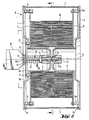
- the housing G of the cassette shown is extremely simple. It consists essentially of only three parts, namely two practically identical end plates 1 and 2 and a circumferential jacket 3, which is contained in circumferential grooves 1a and 2a of the end plates 1 and 2.
- the two end plates 1 and 2 each have an inwardly projecting protuberance in the form of a hollow cylindrical pin 4 or 5. These two pins run coaxially and together form the bearing mandrel for the roll W of photographic strip material to be accommodated in the cassette.
- a guide plate 6 or 7 is arranged in parallel at a distance to guide the winding W at the end.
- the guide plate 6 is arranged in a fixed manner with respect to the end plate 2 via fixed spacer bolts 6a.
- the guide plate 7, on the other hand, is movable in the direction of the pin or bearing pin axis A, springs 8 attached to the associated end plate 1 ensure that the guide plate 7 always presses with a preselected pressure laterally against the winding W and thereby guides it exactly and in brakes required dimension.
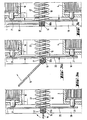
- a single locking element in the form of a screw bolt 10 is provided, which runs coaxially with the cylindrical pins 4 and 5. It is rotatably mounted in a bearing bush 11 formed on the pin 4 and engages with its threaded end 10a in a threaded bore 12 provided on the pin 5.
- a lock nut 13 and a locking ring 14 limit the axial mobility of the screw bolt in the bearing bush 11.
- the bolt 10 protrudes on the side of the end plate 1 from the housing G and carries at its end 10 b a plate-shaped rotating member 15.
- This rotating member or this handle is provided with a cam member 16, the function of which is still to be explained, and on the outside End 10b of the bolt 10 is pivotally or foldably fastened about a folding axis 17 perpendicular thereto.
- the handle 15 lies parallel to the screw bolt 10 and can thus be actuated to rotate the latter (working position).
- FIG. 2 In one extreme position (FIG. 2), the handle 15 lies parallel to the screw bolt 10 and can thus be actuated to rotate the latter (working position). In the other extreme position (FIG.
- a dome plate 20 is provided, which is coupled to the guide plate 7 in the interior of the housing by pressure by means of spacer bolts 21 which pass through recesses in the end plate 1.
- the spacer bolts are only attached to the guide plate 7, but not to the coupling plate 20.
- the dome plate 20 rests, as shown in FIG. 2, due to the action of a compression spring 22 which surrounds the screw bolt 10 against the cam member 16, which is approximately square in cross section, on the handle 15, the spacer bolts 21 being out of contact with the dome plate 20 are. From the shape of the cam member 16 it can be seen that the dome plate 20 is furthest out in the two extreme positions of the handle (FIGS.
- the screw bolt 10 is loosened until it is out of engagement with the threaded bore 12 in the pin 5, and then the end plate 1 is removed. After insertion, the face plate 1 is put back on and the screw bolt 10 is tightened by means of the handle 15 until the housing is properly closed. When the handle 15 is then folded into the rest position, the aforementioned automatic alignment of the winding W then occurs.
- the jacket 3 of the cassette housing has in its upper part on one side a laterally projecting connection mouth 30, which is used for insertion into a corresponding connection opening in an automatic copying machine and thus for light-tight coupling to it.
- the mouth 30 contains a light-tight closure 31 which opens automatically when coupled to the copier.
- the mouth also contains coding means in the form of e.g. four small permanent magnets 32, which can be evaluated by reading means provided in the copying machine, preferably Hall sensors with associated electronics, and contain information about the width of the strip material currently in use.
- the use of small permanent magnets is a particularly simple and expedient type of coding which, above all, allows the coded information to be changed very easily and conveniently.
- the magnets are only loosely arranged in corresponding bores, and in order to change the information, a desired number of permanent magnets in a desired arrangement and desired polarization direction are simply inserted into these bores, the code representing the information being formed by the presence and the polarization direction of the permanent magnets .
- the code representing the information being formed by the presence and the polarization direction of the permanent magnets .
- Fig. 1 the coupling of the cassette to a copier is indicated. However, only one side wall 41 of the copying machine is shown with the insertion opening 42 for the connecting mouth 30 and a pair of transport rollers 43 and 44 for the strip material and an inlet slope 45 for actuating the light-tight closure indicated in the cassette mouth 30.
- the permanent magnets are symbolized by position 32.
- the cassette according to the invention described above is structurally extremely simple overall, extremely reliable in operation and very easy to handle.
Description
Die Erfindung betrifft eine Kassette gemäss dem Oberbegriff des Patentanspruchs 1, wie sie aus der US-A-3612 424 bekannt ist.The invention relates to a cassette according to the preamble of
Derartige Kassetten sind in zahlreichen Ausführungen bekannt. Sie werden vor allem in Fotolabors in Verbindung mit mehr oder weniger stark automatisierten Kopiergeräten eingesetzt, an die sie eingangsseitig lichtdicht angekoppelt werden können, um sie mit unbelichtetem Fotopapier zu versorgen. Einzelne Kassetten sind auch dazu ausgebildet, sowohl eingangsseitig als auch ausgangsseitig an das Kopiergerät angeschlossen werden zu können, also auch belichtetes Kopiermaterial vom Kopiergerät aufzunehmen.Such cassettes are known in numerous designs. They are used primarily in photo laboratories in connection with more or less highly automated copying machines, to which they can be coupled light-tight on the input side in order to supply them with unexposed photo paper. Individual cassettes are also designed to be able to be connected to the copier both on the input side and on the output side, that is to say also to receive exposed copying material from the copier.
Durch die vorliegende Erfindung soll nun eine neue Kassette der im Oberbegriff des Patentanspruchs 1 definierten Art geschaffen werden, welche sich durch besondere konstruktive Einfachheit, grossen Bedienungskomfort und höchste funktionelle Zuverlässigkeit auszeichnet.The present invention is now to create a new cassette of the type defined in the preamble of
Die erfindungsgemässe Kassette, die diese Anforderungen erfüllt, ist im Patentanspruch 1 beschrieben. Besonders zweckmässige und vorteilhafte Ausgestaltungen ergeben sich aus den abhängigen Ansprüchen.The cassette according to the invention, which meets these requirements, is described in
Im folgenden wird die Erfindung anhand eines in der Zeichnung dargestellten Ausführungsbeispiels näher erläutert. Es zeigen :
- Fig. 1 eine nach der Linie I-I in Fig. 2 teilweise geschnittene Seiten- oder Stirnansicht einer erfindungsgemässen Kassette,
- Fig. 2 einen Querschnitt nach der Linie 11-11 der Fig. 1 und
- Fig.3a bis 3c je einen Detailschnitt nach der Linie 111-111 der Fig.2 in drei unterschiedlichen Klappstellungen eines Details.
- 1 is a side or end view of a cassette according to the invention, partially sectioned along line II in FIG. 2,
- Fig. 2 shows a cross section along the line 11-11 of Fig. 1 and
- 3a to 3c each a detail section along the line 111-111 of Fig.2 in three different folding positions of a detail.
Wie die Figuren 1 und 2 deutlich erkennen lassen, ist das Gehäuse G der dargestellten Kassette äusserst einfach aufgebaut. Es besteht im wesentlichen aus nur drei Teilen, und zwar zwei praktisch gleich ausgebildeten Stirnplatten 1 und 2 und einem umlaufenden Mantel 3, der in Umfangsnuten 1a und 2a der Stirnplatten 1 und 2 gefasst ist.As can be clearly seen in FIGS. 1 and 2, the housing G of the cassette shown is extremely simple. It consists essentially of only three parts, namely two practically
Die beiden Stirnplatten 1 und 2 weisen je eine nach innen vorspringende Ausstülpung in Form eines hohlzylindrischen Zapfens 4 bzw. 5 auf. Diese beiden Zapfen verlaufen koaxial und bilden gemeinsam den Lagerdorn für den in der Kassette aufzunehmenden Wickel W fotografischen Bandmaterials.The two
An den Stirnplatten 1 und 2 ist innen parallel im Abstand je eine Führungsplatte 6 bzw. 7 zur stirnseitigen Führung des Wickels W angeordnet. Die Führungsplatte 6 ist über fixe Distanzbolzen 6a ortsfest in Bezug auf die Stirnplatte 2 angeordnet. Die Führungsplatte 7 dagegen ist in Richtung der Zapfen- bzw. Lagerdornachse A beweglich, wobei an der zugeordneten Stirnplatte 1 befestigte Federn 8 dafür sorgen, dass die Führungsplatte 7 stets mit einem vorgewählten Druck seitlich gegen den Wickel W presst und diesen dadurch exakt führt und im erforderlichen Mass bremst.On the
Zum Zusammenhalt des Kassettengehäuses G ist ein einziges Schliessorgan in Form eines Schraubbolzens 10 vorgesehen, welcher koaxial zu den zylindrischen Zapfen 4 und 5 verläuft. Er ist in einer am Zapfen 4 angeformten Lagerbüchse 11 drehbar gelagert und greift mit seinem Gewindeende 10a in eine am Zapfen 5 vorgesehene Gewindebohrung 12 ein. Eine Kontermutter 13 und ein Sicherungsring 14 begrenzen die axiale Beweglichkeit des Schraubbolzens in der Lagerbüchse 11.To hold the cassette housing G together, a single locking element in the form of a
Der Schraubbolzen 10 ragt auf der Seite der Stirnplatte 1 aus dem Gehäuse G heraus und trägt an seinem Ende 10 b ein plattenförmiges Drehorgan 15. Dieses Drehorgan bzw. dieser Handgriff ist mit einem Nockenorgan 16 versehen, dessen Funktion noch zu erläutern ist, und am äusseren Ende 10b des Schraubbolzens 10 um eine zu diesem senkrechte Klappachse 17 schwenk- bzw. klappbar befestigt. In der einen Extremstellung (Fig.2) liegt der Handgriff 15 parallel zum Schraubbolzen 10 und kann so zum Verdrehen des letzteren betätigt werden (Arbeitsstellung). In der anderen Extremstellung (Fig. 1) liegt er um 90° geklappt, also parallel zur Stirnplatte 1, und ist dabei in einer muldenförmigen Einbuchtung 18 der Stirnplatte 1 versenkt und im wesentlichen bündig mit der diese Einbuchtung umgebenden Fläche der Stirnplatte. Diese Extremstellung ist die beim Einsatz der Kassette eingenommene Ruhestellung.The
In der muldenförmigen Einbuchtung 18 ist eine Kuppelplatte 20 vorgesehen, die mittels durch Ausnehmungen in der Stirnplatte 1 hindurchgreifender Distanzbolzen 21 auf Druck mit der Führungsplatte 7 im Gehäuseinneren gekoppelt ist. Die Distanzbolzen sind nur an der Führungsplatte 7, nicht jedoch an der Kuppelplatte 20 befestigt. In geschlossenem Zustand der Kassette liegt die Kuppelplatte 20, wie in Fig. 2 dargestellt aufgrund der Wirkung einer den Schraubbolzen 10 umschliessenden Druckfeder 22 federnd an dem im Querschnitt in etwa quadratischen Nockenorgan 16 am Handgriff 15 an, wobei die Distanzbolzen 21 ausser Kontakt mit der Kuppelplatte 20 sind. Aus der Form des Nockenorgans 16 ist ersichtlich, dass sich die Kuppelplatte 20 in den beiden Extremstellungen des Handgriffs (Figs. 3a and 3c) am weitesten aussen und damit die Führungsplatte 7 am nächsten bei der zugeordneten Stirnplatte 1 befindet:' Beim Hoch- bzw. Niederklappen des Handgriffs 15 wird jedoch die Kuppelplatte 20 und damit via Distanzbolzen 21 die Führungsplatte 7 entgegen der Wirkung der Druckfeder 22 vorübergehend einwärts bewegt (Fig. 3b). Durch diese Einwärtsbewegung wird am Wickel ein Richteffekt erzielt, d.h. allenfalls hervorstehende Lagen des Wickels werden wieder sauber ausgerichtet und bündig gemacht. Dabei ist es von Vorteil, dass die Ausrichtung des Wickels automatisch beim Verschliessen des Kassettengehäuses geschieht, ohne dass dazu irgendwelche besonderen Handgriffe benötigt wären.In the trough-
Zum Einlegen eines Wickels W wird der Schraubbolzen 10 gelöst, bis er ausser Eingriff mit der Gewindebohrung 12 im Zapfen 5 ist, und dann die Stirnplatte 1 abgenommen. Nach dem Einlegen wird die Stirnplatte 1 wieder aufgesetzt und der Schraubbolzen 10 mittels des Handgriffs 15 angezogen, bis das Gehäuse satt verschlossen ist. Beim danach erfolgenden Umklappen des Handgriffs 15 in die Ruhestellung kommt es dann zu der schon erwähnten automatischen Ausrichtung des Wickels W.To insert a winding W, the
Der Mantel 3 des Kassettengehäuses weist in seinem oberen Teil an einer Seite ein seitlich wegstehendes Anschlussmaul 30 auf, das zum Einführen in eine entsprechende Anschlussöffnung in einem automatischen Kopiergerät und damit zum lichtdichten Ankoppeln an dieses dient. Durch dieses Maul 30 wird das in der Kassette befindliche Bandmaterial dem Kopiergerät zugeführt. Das Maul 30 enthält einen lichtdichten Verschluss 31, der sich beim Ankoppeln an das Kopiergerät automatisch öffnet. Ferner enthält das Maul auch noch Kodiermittel in Form von z.B. vier kleinen Permanentmagneten 32, die von im Kopiergerät vorgesehenen Lesemitteln, vorzugsweise Hallsensoren mit zugeordneter Elektronik, ausgewertet werden können und eine Information über die Breite des gerade im Einsatz befindlichen Bandmaterials beinhalten. Die Verwendung von kleinen Permanentmagneten ist eine besonders einfache und zweckmässige Kodierungsart, die vor allem eine sehr einfache und bequeme Änderung der kodierten Information zulässt. Die Magneten sind dazu nur lose in entsprechenden Bohrungen angeordnet, und zur Änderung der Information wird einfach eine gewünschte Anzahl von Permanentmagneten in gewünschter Anordnung und gewünschter Polarisationsrichtung in diese Bohrungen eingelegt, wobei der die Information darstellende Code durch das Vorhandensein und die Polarisationsrichtung der Permanentmagneten gebildet ist. Bei beispielweise vier Permanentmagneten sind so 81 verschiedene Informationen codierbar.The
In Fig. 1 ist die Ankopplung der Kassette an ein Kopiergerät angedeutet. Vom Kopiergerät ist allerdings nur eine Seitenwand 41 mit der Einfuhröffnung 42 für das Anschlussmaul 30 sowie ein Transportrollenpaar 43 und 44 für das Bandmaterial und eine Einlaufschräge 45 zur Betätigung des mit 31 angedeuteten lichtdichten Verschlusses im Kassettenmaul 30 dargestellt. Die Permanentmagneten sind durch die Position 32 symbolisiert.In Fig. 1 the coupling of the cassette to a copier is indicated. However, only one
Die vorstehend beschriebene, erfindungsgemässe Kassette ist insgesamt konstruktiv extrem einfach, äusserst zuverlässig im Betrieb und sehr einfach handzuhaben.The cassette according to the invention described above is structurally extremely simple overall, extremely reliable in operation and very easy to handle.
Claims (11)
Applications Claiming Priority (2)
| Application Number | Priority Date | Filing Date | Title |
|---|---|---|---|
| CH3290/85 | 1985-07-30 | ||
| CH329085 | 1985-07-30 |
Publications (2)
| Publication Number | Publication Date |
|---|---|
| EP0214928A1 EP0214928A1 (en) | 1987-03-18 |
| EP0214928B1 true EP0214928B1 (en) | 1989-03-15 |
Family
ID=4252785
Family Applications (1)
| Application Number | Title | Priority Date | Filing Date |
|---|---|---|---|
| EP86810336A Expired EP0214928B1 (en) | 1985-07-30 | 1986-07-24 | Cassette for web-like photographic material |
Country Status (5)
| Country | Link |
|---|---|
| US (1) | US4741439A (en) |
| EP (1) | EP0214928B1 (en) |
| JP (1) | JPH0690449B2 (en) |
| DE (1) | DE3662472D1 (en) |
| DK (1) | DK162499C (en) |
Families Citing this family (22)
| Publication number | Priority date | Publication date | Assignee | Title |
|---|---|---|---|---|
| JPH01176649U (en) * | 1988-06-03 | 1989-12-15 | ||
| DE68926552T2 (en) * | 1988-08-05 | 1996-12-12 | Minolta Camera Kk | Film cassette and camera for such a cassette |
| US5271577A (en) * | 1989-07-04 | 1993-12-21 | Fuji Photo Film Co., Ltd. | Photographic film cassette |
| DE69022894T2 (en) * | 1989-07-04 | 1996-04-04 | Fuji Photo Film Co Ltd | Cassette for a photographic film. |
| US5031853A (en) * | 1990-01-12 | 1991-07-16 | Eastman Kodak Company | Film-thrusting cassette |
| FR2658156B1 (en) * | 1990-02-12 | 1992-06-12 | Kodak Pathe | PACKAGING METHOD, PACKAGING AND DEVICE FOR HANDLING BANDED PRODUCTS. |
| DE9002409U1 (en) * | 1990-03-01 | 1990-05-03 | Du Pont De Nemours (Deutschland) Gmbh, 6380 Bad Homburg, De | |
| FR2663007A1 (en) * | 1990-06-08 | 1991-12-13 | Kodak Pathe | Packaging for photographic products in strips |
| FR2663132B1 (en) * | 1990-06-11 | 1993-05-28 | Kodak Pathe | INTERFACING DEVICE BETWEEN A DEBITTING STATION AND A PHOTOGRAPHIC FILM RECEIVING STATION. |
| EP0463997B1 (en) * | 1990-06-29 | 1995-01-18 | Gretag Imaging Ag | Cassette for winding a web of photographic material |
| JP2915619B2 (en) * | 1991-05-13 | 1999-07-05 | 富士写真フイルム株式会社 | Paper magazine mounting device and method |
| US5161685A (en) * | 1991-07-31 | 1992-11-10 | Eastman Kodak Company | Flexible light-tight enclosure for photosensitive web roll |
| US5236143A (en) * | 1991-10-23 | 1993-08-17 | Dragon Bradley P | Intravenous tubing retractor apparatus |
| US5275347A (en) * | 1992-01-10 | 1994-01-04 | Management Graphics, Inc. | Autothread mechanism for strip material |
| EP0561438A1 (en) * | 1992-03-19 | 1993-09-22 | Agfa-Gevaert N.V. | A reloadable lighttight plastic cassette |
| CA2096054A1 (en) * | 1992-07-30 | 1994-01-31 | Alan D. Frazier | Rolled tissue dispenser |
| US5390872A (en) * | 1993-09-30 | 1995-02-21 | Eastman Kodak Company | Package for rolls of photosensitive web |
| GB2327934A (en) * | 1997-07-31 | 1999-02-10 | Tony Sandland | Coil holder for variable coil thicknesses |
| US6238113B1 (en) * | 1999-09-30 | 2001-05-29 | Agfa Corporation | Media feed apparatus for imaging system |
| US6601790B2 (en) * | 2001-08-06 | 2003-08-05 | American Printing Components, Llc | Reusable cassette for photosensitive film |
| US7549602B2 (en) * | 2006-03-22 | 2009-06-23 | Hitachi Maxell, Ltd. | Tape cartridge |
| US9480371B2 (en) | 2011-05-02 | 2016-11-01 | Hardware Resources, Inc. | Self-securing roll holder and method |
Family Cites Families (16)
| Publication number | Priority date | Publication date | Assignee | Title |
|---|---|---|---|---|
| US2389495A (en) * | 1945-01-12 | 1945-11-20 | Miner Inc W H | Film holder |
| US3036207A (en) * | 1960-01-14 | 1962-05-22 | Mcphilben Mfg Co Inc | Lighting fixture |
| DE1258268B (en) * | 1962-06-14 | 1968-01-04 | Morningstar Corp | Film reel cassette |
| US3212729A (en) * | 1963-04-22 | 1965-10-19 | Gene M Putnam | Wire dispensing apparatus |
| US3353660A (en) * | 1965-08-19 | 1967-11-21 | Minnesota Mining & Mfg | Shipping container |
| BE754899A (en) * | 1969-08-15 | 1971-01-18 | Cement & Concrete Ass | METHOD AND APPARATUS FOR THE CONSTRUCTION OF RIGID ROADS WITH A TEXTURED SURFACE |
| US3612424A (en) * | 1970-03-27 | 1971-10-12 | Visual Graphics Corp | Storage and dispensing magazine for rolled strips of light sensitized material |
| DE2048684A1 (en) * | 1970-10-03 | 1972-04-06 | Norpnnt Ltd , Boston, Lincolnshire (Großbritannien) | Cassette for storing and removing tape rolls |
| JPS5213929B2 (en) * | 1972-09-07 | 1977-04-18 | ||
| US4272035A (en) | 1980-04-14 | 1981-06-09 | Eastman Kodak Company | Light lock for roll dispensing container |
| JPS57128333A (en) * | 1980-12-09 | 1982-08-09 | Agfa Gevaert Nv | Roll holding/delivering cassette for web material |
| JPS58133581U (en) * | 1982-03-01 | 1983-09-08 | 松原 出 | Package for circular products |
| EP0100896B1 (en) * | 1982-07-19 | 1988-01-20 | Horstmann-Electronic | Magnetic coding arrangement for a workpiece |
| US4534519A (en) * | 1983-02-08 | 1985-08-13 | Pako Corporation | Photographic paper roll core holding device |
| EP0145813B1 (en) * | 1983-12-12 | 1988-02-03 | Agfa-Gevaert N.V. | Light-tight cassette |
| JPH0480374A (en) * | 1990-07-23 | 1992-03-13 | Nippondenso Co Ltd | Production of printed circuit board |
-
1986
- 1986-07-24 EP EP86810336A patent/EP0214928B1/en not_active Expired
- 1986-07-24 DE DE8686810336T patent/DE3662472D1/en not_active Expired
- 1986-07-29 DK DK359286A patent/DK162499C/en not_active IP Right Cessation
- 1986-07-29 US US06/890,274 patent/US4741439A/en not_active Expired - Lifetime
- 1986-07-30 JP JP61177863A patent/JPH0690449B2/en not_active Expired - Lifetime
Also Published As
| Publication number | Publication date |
|---|---|
| JPS6258243A (en) | 1987-03-13 |
| JPH0690449B2 (en) | 1994-11-14 |
| DE3662472D1 (en) | 1989-04-20 |
| DK359286A (en) | 1987-01-31 |
| DK162499C (en) | 1992-06-01 |
| DK162499B (en) | 1991-11-04 |
| EP0214928A1 (en) | 1987-03-18 |
| US4741439A (en) | 1988-05-03 |
| DK359286D0 (en) | 1986-07-29 |
Similar Documents
| Publication | Publication Date | Title |
|---|---|---|
| EP0214928B1 (en) | Cassette for web-like photographic material | |
| EP0021388B1 (en) | Apparatus for cutting vertical paper webs | |
| DE2907722C3 (en) | Paper sheet magazine closed on all sides for removable insertion in a paper sheet dispenser | |
| DE2925837C2 (en) | Film cassette with a window for imprinting data | |
| DE3346025C2 (en) | ||
| EP0037484B1 (en) | Device for positioning and fastening a test stripe for optical medical measurements | |
| DE2553861A1 (en) | PHOTOGRAPHIC CAMERA WITH INTERCHANGEABLE LENS | |
| EP0270486A1 (en) | Daylight cassette | |
| EP0207059B1 (en) | Operating mechanism for a loose-leaf binder | |
| DE2945840A1 (en) | SHEET FEEDING CASSETTE FOR A COPIER | |
| DE2532812A1 (en) | CASSETTE HOLDER FOR A DEVICE FOR MAGNETIC RECORDING AND / OR REPLAY OF SIGNALS | |
| DE1815850B2 (en) | DEVICE IN OR ON A COPY MACHINE WITH SPACIOUSLY SEPARATED FEED TABLES FOR COPY PAPER AND ORIGINAL | |
| DE2608504A1 (en) | CASSETTE RECORDER OR PLAYER | |
| DE3230633C2 (en) | Magnetic lock | |
| DE2651407C3 (en) | Roll cassette | |
| DE1598918C3 (en) | Lifting device for raising and lowering sample carriers | |
| DE2820136C2 (en) | Printing press | |
| DE3615495C2 (en) | Drive device for a winding and unwinding device for web material with bobbins | |
| DE3637246A1 (en) | ARRANGEMENT FOR INSERTING AND REMOVING A CASSETTE IN AN ELECTRONIC STILL CAMERA | |
| DE2210753B2 (en) | Device for closing containers | |
| EP0463997A1 (en) | Cassette for winding a web of photographic material | |
| DE1554610C (en) | Device for successive dispensing of strip-shaped material | |
| DE2504633C3 (en) | Cassette reel driving device for a cassette camera | |
| DE7822228U1 (en) | DEVICE FOR DISPLAYING FILM REMAINING ON A FILM REEL | |
| DE2930711C2 (en) | Instant camera |
Legal Events
| Date | Code | Title | Description |
|---|---|---|---|
| PUAI | Public reference made under article 153(3) epc to a published international application that has entered the european phase |
Free format text: ORIGINAL CODE: 0009012 |
|
| 17P | Request for examination filed |
Effective date: 19860726 |
|
| AK | Designated contracting states |
Kind code of ref document: A1 Designated state(s): CH DE FR GB IT LI |
|
| 17Q | First examination report despatched |
Effective date: 19880222 |
|
| GRAA | (expected) grant |
Free format text: ORIGINAL CODE: 0009210 |
|
| AK | Designated contracting states |
Kind code of ref document: B1 Designated state(s): CH DE FR GB IT LI |
|
| REF | Corresponds to: |
Ref document number: 3662472 Country of ref document: DE Date of ref document: 19890420 |
|
| ET | Fr: translation filed | ||
| ITF | It: translation for a ep patent filed |
Owner name: SOCIETA' ITALIANA BREVETTI S.P.A. |
|
| GBT | Gb: translation of ep patent filed (gb section 77(6)(a)/1977) | ||
| PLBE | No opposition filed within time limit |
Free format text: ORIGINAL CODE: 0009261 |
|
| STAA | Information on the status of an ep patent application or granted ep patent |
Free format text: STATUS: NO OPPOSITION FILED WITHIN TIME LIMIT |
|
| 26N | No opposition filed | ||
| REG | Reference to a national code |
Ref country code: GB Ref legal event code: 727 |
|
| ITTA | It: last paid annual fee | ||
| REG | Reference to a national code |
Ref country code: CH Ref legal event code: PVP Owner name: QUALEX INC. |
|
| REG | Reference to a national code |
Ref country code: CH Ref legal event code: PUE Owner name: GRETAG AKTIENGESELLSCHAFT TRANSFER- GRETAG IMAGING |
|
| REG | Reference to a national code |
Ref country code: GB Ref legal event code: 732E |
|
| REG | Reference to a national code |
Ref country code: FR Ref legal event code: TP |
|
| PGFP | Annual fee paid to national office [announced via postgrant information from national office to epo] |
Ref country code: GB Payment date: 20000614 Year of fee payment: 15 |
|
| PGFP | Annual fee paid to national office [announced via postgrant information from national office to epo] |
Ref country code: CH Payment date: 20000616 Year of fee payment: 15 |
|
| PGFP | Annual fee paid to national office [announced via postgrant information from national office to epo] |
Ref country code: FR Payment date: 20000629 Year of fee payment: 15 Ref country code: DE Payment date: 20000629 Year of fee payment: 15 |
|
| PG25 | Lapsed in a contracting state [announced via postgrant information from national office to epo] |
Ref country code: GB Free format text: LAPSE BECAUSE OF NON-PAYMENT OF DUE FEES Effective date: 20010724 |
|
| PG25 | Lapsed in a contracting state [announced via postgrant information from national office to epo] |
Ref country code: LI Free format text: LAPSE BECAUSE OF NON-PAYMENT OF DUE FEES Effective date: 20010731 Ref country code: CH Free format text: LAPSE BECAUSE OF NON-PAYMENT OF DUE FEES Effective date: 20010731 |
|
| GBPC | Gb: european patent ceased through non-payment of renewal fee |
Effective date: 20010724 |
|
| REG | Reference to a national code |
Ref country code: CH Ref legal event code: PL |
|
| PG25 | Lapsed in a contracting state [announced via postgrant information from national office to epo] |
Ref country code: FR Free format text: LAPSE BECAUSE OF NON-PAYMENT OF DUE FEES Effective date: 20020329 |
|
| PG25 | Lapsed in a contracting state [announced via postgrant information from national office to epo] |
Ref country code: DE Free format text: LAPSE BECAUSE OF NON-PAYMENT OF DUE FEES Effective date: 20020501 |
|
| REG | Reference to a national code |
Ref country code: FR Ref legal event code: ST |
|
| PG25 | Lapsed in a contracting state [announced via postgrant information from national office to epo] |
Ref country code: IT Free format text: LAPSE BECAUSE OF NON-PAYMENT OF DUE FEES;WARNING: LAPSES OF ITALIAN PATENTS WITH EFFECTIVE DATE BEFORE 2007 MAY HAVE OCCURRED AT ANY TIME BEFORE 2007. THE CORRECT EFFECTIVE DATE MAY BE DIFFERENT FROM THE ONE RECORDED. Effective date: 20050724 |