EP0214799B1 - Closure for a container - Google Patents
Closure for a container Download PDFInfo
- Publication number
- EP0214799B1 EP0214799B1 EP86306506A EP86306506A EP0214799B1 EP 0214799 B1 EP0214799 B1 EP 0214799B1 EP 86306506 A EP86306506 A EP 86306506A EP 86306506 A EP86306506 A EP 86306506A EP 0214799 B1 EP0214799 B1 EP 0214799B1
- Authority
- EP
- European Patent Office
- Prior art keywords
- collar
- closure
- plug
- container
- container assembly
- Prior art date
- Legal status (The legal status is an assumption and is not a legal conclusion. Google has not performed a legal analysis and makes no representation as to the accuracy of the status listed.)
- Expired
Links
- 238000007789 sealing Methods 0.000 claims abstract description 17
- 239000000463 material Substances 0.000 claims description 9
- 238000013022 venting Methods 0.000 claims description 9
- 239000011324 bead Substances 0.000 claims description 3
- 235000014171 carbonated beverage Nutrition 0.000 abstract description 4
- 230000035622 drinking Effects 0.000 description 2
- 230000002706 hydrostatic effect Effects 0.000 description 2
- 238000012986 modification Methods 0.000 description 2
- 230000004048 modification Effects 0.000 description 2
- 239000004033 plastic Substances 0.000 description 2
- 229920003023 plastic Polymers 0.000 description 2
- -1 polypropylene Polymers 0.000 description 2
- 239000004677 Nylon Substances 0.000 description 1
- 239000004698 Polyethylene Substances 0.000 description 1
- 239000004743 Polypropylene Substances 0.000 description 1
- 230000004323 axial length Effects 0.000 description 1
- 235000013405 beer Nutrition 0.000 description 1
- 235000013361 beverage Nutrition 0.000 description 1
- 230000015572 biosynthetic process Effects 0.000 description 1
- 238000010276 construction Methods 0.000 description 1
- 239000013013 elastic material Substances 0.000 description 1
- 238000003780 insertion Methods 0.000 description 1
- 230000037431 insertion Effects 0.000 description 1
- 239000002184 metal Substances 0.000 description 1
- 238000000034 method Methods 0.000 description 1
- 229920001778 nylon Polymers 0.000 description 1
- 230000002093 peripheral effect Effects 0.000 description 1
- 229920000573 polyethylene Polymers 0.000 description 1
- 229920001155 polypropylene Polymers 0.000 description 1
- 238000004080 punching Methods 0.000 description 1
- 230000000717 retained effect Effects 0.000 description 1
- 238000004826 seaming Methods 0.000 description 1
Images


Classifications
-
- B—PERFORMING OPERATIONS; TRANSPORTING
- B65—CONVEYING; PACKING; STORING; HANDLING THIN OR FILAMENTARY MATERIAL
- B65D—CONTAINERS FOR STORAGE OR TRANSPORT OF ARTICLES OR MATERIALS, e.g. BAGS, BARRELS, BOTTLES, BOXES, CANS, CARTONS, CRATES, DRUMS, JARS, TANKS, HOPPERS, FORWARDING CONTAINERS; ACCESSORIES, CLOSURES, OR FITTINGS THEREFOR; PACKAGING ELEMENTS; PACKAGES
- B65D39/00—Closures arranged within necks or pouring openings or in discharge apertures, e.g. stoppers
- B65D39/12—Closures arranged within necks or pouring openings or in discharge apertures, e.g. stoppers expansible, e.g. inflatable
-
- B—PERFORMING OPERATIONS; TRANSPORTING
- B65—CONVEYING; PACKING; STORING; HANDLING THIN OR FILAMENTARY MATERIAL
- B65D—CONTAINERS FOR STORAGE OR TRANSPORT OF ARTICLES OR MATERIALS, e.g. BAGS, BARRELS, BOTTLES, BOXES, CANS, CARTONS, CRATES, DRUMS, JARS, TANKS, HOPPERS, FORWARDING CONTAINERS; ACCESSORIES, CLOSURES, OR FITTINGS THEREFOR; PACKAGING ELEMENTS; PACKAGES
- B65D39/00—Closures arranged within necks or pouring openings or in discharge apertures, e.g. stoppers
- B65D39/04—Cup-shaped plugs or like hollow flanged members
Definitions
- the invention relates to a closure and container assembly and in particular relates to a resealable closure and container assembly for carbonated beverages.
- Prior closures which comprise a collar which is fitted into an opening in a container and a plug which then fits into and closes the collar.
- the collar is dimensioned to provide a permanent sealing fit within the opening and the plug is dimensioned to provide a tight sealing fit within the collar.
- Containers employing such closures can be resealed after opening by replacing the plug in the collar. There is, therefore, a primary or permanent seal between the collar and the container and a secondary or re-usable seal between the plug and the collar.
- Such closures are known for example from CH-A-338108, FR-A-1194211 and NL-A-6509615.
- a closure known from DE-A-2146267 is provided with a collar which is relatively elastic and is an easy fit in the opening in the relaxed state, and in which the plug is relatively stiff so that when inserted into the collar it closes the opening and causes the collar to be elastically deformed into tight sealing engagement with the opening and with the plug.
- the primary seal is thus effected at the same time as the secondary seal by insertion of the plug into the collar.
- FR-A-1194211 discloses a closure and container assembly, the container having an opening therein which includes a closure-engaging surface, and the closure comprising an annular collar, having a neck adapted to be located in the opening and a radial flange connected to the neck at its end outside the container, and a plug hingedly connected to the collar, wherein the collar is relatively elastic, is an easy fit in the opening in a relaxed state, and defines an opening through which the contents of the container can be poured after removal of the plug, and the plug is relatively stiff so that when the plug is inserted into the collar it closes the opening and expands the collar into sealing engagement with the closure engaging surface, the collar further comprising a thickened portion connected to the neck of the collar at its end within the container, the inner wall of the thickened portion being flared inwardly and downwardly with respect to the longitudinal axis of the annular collar.
- the present invention provides a closure and container assembly in which the container has an opening therein which includes a frusto-conical closure-engaging surface which flares outwardly into the container.
- a closure and container assembly the container having an opening therein which includes a closure-engaging surface
- the closure comprising an annular collar, having a neck adapted to be located in the opening and a radial flange connected to the neck at its end outside the container, and a plug hingedly connected to the collar, wherein the collar is relatively elastic, is an easy fit in the opening in a relaxed state, and defines an opening through which the contents of the container can be poured after removal of the plug, and the plug is relatively stiff so that when the plug is inserted into the collar it closes the opening and expands the collar into sealing engagement with the closure engaging surface, the collar further comprising a thickened portion connected to the neck of the collar at its end within the container, the inner wall of the thickened portion being flared inwardly and downwardly with respect to the longitudinal axis of the annular collar ; characterised in that, in the relaxed condition, and the outer wall of the thickened portion is flared outwardly and downwardly with respect to the longitudinal axis
- the neck of the collar is substantially cylindrical.
- the collar is provided with an annular groove and the plug is provided with an annular bead adapted to snap fit into the annular groove when the plug is inserted into the collar.
- the collar is provided with a substantially axial venting groove extending from the end of the neck of the collar outside the container to a point slightly spaced from the annular groove.
- a closure 1 is shown fitted into a circular opening formed in the end 2 of a metal container or can (not shown).
- the opening is defined by an annular wall 3 which is formed on the can end by punching or otherwise cutting out a hole in the can end and forming the surrounding material.
- the wall 3 comprises an upper portion 4 which is curved in section and terminates in a substantially vertical end face 5 and a sealing portion 6 which adjoins the upper portion at the narrowest point of the opening and flares outwardly into the can at an angle A to the axis of the closure.
- the radially inner surface of the wall portion 6 provides a frusto-conical surface 6' for sealing engagement with the collar.
- the angle A is preferably in the range of 5° to 45° and is more preferably in the range of 10° to 20°.
- the sealing portion of the wall 3 is connected to the rest of the can end by a lower curved portion 7 and an annular ramp 8 which is inclined to the can end at an angle B.
- the angle B is preferably in the range of 130° to 150° and more preferably is about 135°.
- the closure 1 which is retained in the opening, comprises three main parts : a collar 9, a plug 10, and a pull tab 11.
- the collar can be pushed into the opening to form an easy fit within the annular wall 3.
- the collar comprises a radial flange 12 supporting a pair of ribs 122, a substantially cylindrical neck 13, and a thickened portion 14 which, in the relaxed condition shown in Figure 1, flares both inwardly and outwardly from the bottom of the neck 13.
- the portion 14 flares inwardly at an angle C to the axis of the closure.
- the angle C is preferably about 10°.
- the portion 14 is provided with an annular locking groove 15 and a substantially axial venting groove 16.
- the groove 16 does not extend the full axial length of the collar, but terminates at a point 17 spaced slightly from the locking groove 15.
- the plug may be attached to the collar such as by a hinge 18, or by a snap fit ring or plug (not shown) which engages a corresponding formation on the collar, or may be separate therefrom.
- the plug comprises a radial flange 19, a cylindrical neck 20, and a bottom wall 21.
- the flange 19 overlies the flange 12 and is substantially surrounded by the ribs 122, the neck 20 is tightly received within the neck 13, and an annular rib 22, formed at the juction between the neck 20 the bottom wall 21, snaps into the locking groove 15.
- the materials, configuration, and dimensions of the plug and collar are selected such that the plug urges the collar against the wall 3 formed in the can end.
- the lower part of the neck 13 and the thickened portion 14 are elastically deformed into sealing engagement with the portions 6 and 7 of the wall 3 and with the plug 9.
- a hydrostatic pressure such as obtains in a can of carbonated beverage to act on the bottom wall 21 of the plug g is delivered to the peripheral junction of cylindrical neck 20 and bottom wall 21 where the locking groove 15 of collar g engages with the annular rib 22 so that a compressive load is imposed on the collar material to press it more tightly onto the frusto-conical surface 6' of the sealing portion 6 which acts as a buttress.
- any hydrostatic pressure within the container will tend to flatten the convexity so imposing a desirable degree of lateral spread to compress the collar.
- a modified convex wall must be stiff enough to prevent any risk of reversal to a concave shape which would relieve the lateral spreading pressure.
- the collar and plug may be made of any suitable material such as polypropylene or nylon if the closure is intended for use in a pressurised beer or beverage can. For products exerting little or no internal pressure, polyethylene may be used.
- the collar is made of relatively elastic material such that it will form a good seal with the can end and with the plug when the relatively stiff plug is inserted.
- the plug may be provided with stiffening ribs (not shown) or stiffened by the provision of a secondary plug (not shown) which is integral with the pull tab and can be fitted inside the neck 20 of the plug.
- a secondary plug not shown
- the collar, plug, and pull tab are integrally moulded of the same material and in this case the relative stiffness of the plug is provided entirely by the configuration of the plug.
- the pull tab 11 is integrally moulded with the plug and is connected thereto by a flexible hinge 23.
- the pull tab lies in the same plane as the flange 19 and effectively forms an extension thereof.
- Dog-legged slots 24 separate the flange 19 from the pull tab and define legs 25 on the pull tab.
- any internal pressure in the can acts to assist the seal between the plug and the collar and between the collar and the can end if the bottom of the plug is slightly convex.
- the convexity of the bottom of the plug may be provided by the bottom wall being part spherical or, as shown, may be provided by an annular chamferred portion 210 of the bottom 21.
- the opening When used in a can end of a carbonated drinks can, the opening may be provided off-centre such that the venting groove 16 is central to the can.
- the left hand side of the closure will be near to the edge of the can to permit drinking through the collar.
- the relatively loose fit of the collar in the can end enables the closure to be rotated after opening so that the plug and pull tab do not get in the way of a drinker.
- the pull tab may be constructed to overlie the plug and be fitted thereto by a snap or plug fit.
- levering legs may be arranged to act on the can end when the pull tab is hingedly lifted off the plug.
- a press tool having a sleeve 30 and a punch 31 slidable therein is used first to snap fit the collar into the can end and hold it flat by means of the sleeve, and then to push the plug into the collar by means of the punch.
- each closure comprises a relatively elastic annular collar 9 and a relatively stiff plug 10 which when inserted into the collar causes the collar to be elastically deformed into tight sealing engagement with the opening of the container and with the plug.
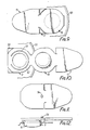
- Figures 7 and 8 show a closure wherein the plug 9 and collar 10 are hingedly connected by tangential limbs 40 and a lift flap 41 is hingedly connected to the plug. After the plug has been pulled out of the collar, the plug may be held flat against the can end as shown in Figure 8. Tamper indicating filaments may be connected between the flap 41 and the limbs 40 when the closure is formed. The filaments are broken when the closure is opened.
- the rim of the can is shown at 50 and the flange of the collar 9 is divided by an incomplete circular slot 51.
- the pull tab, plug, and the outer part 52 of the collar can be pulled away from the edge of the can to permit pouring or drinking through the collar.
- the plug flange is overlain with slight clearance by a pair of vent control latches 53. The plug is momentarily held up by the latches as it is removed from the collar.
- FIGs 11 and 12 an embodiment similar to that of Figures 9 and 10 is provided with a latch peg 54 which stands on the flange of the collar 9, and passes through a slightly undersized aperture in the flange of the plug 10.
- the latch peg thus momentarily interrupts removal of the plug and ensures that venting is achieved before the plug is fully removed.
- Figures 13 and 14 is similar to that of Figures 8 and 9 except that a rib 60 is provided in the plug 10 to add strength to the plug and to provide a lever for lifting the plug from the collar 9.
- the pull tab is provided by a ring 70 attached to the plug.
- the plug 10 is also strengthened by a cruciform rib 71.
- Figures 17, 18 and 19 is similar to that of Figures 9 and 10 except that the pull tab 11 is connected to the plug 10 by a hinge 80 so as to fold back over the plug, in which position a plugging portion 81 on the pull tab is a fairly loose push fit into the top of the plug.
- a hinge 82 allows a segment 83 of the pull tab to be raised from the folded portion shown in Figure 17 so that the pull tab can be lifted off the plug.
- a small upstanding wall 84 on the flange of the collar 9 provides a pivot point for the edge of the pull tab to assist in removal of the plug.
- Figure 20 shows a version of a closure similar to that of Figures 7 and 8 wherein the plug 10 forms an overcap for the collar 9 and is held thereon by engagement of an annular rib 90 on the plug in an annular groove 91 on the collar.
- the raw end face 5 of the opening curl is shown as being outside the container but the opening could be constructed with this edge inside the container if non-aggressive products are to be packed.
- Figure 21 shows a closure 1 comprising a collar 9 and a plug 10 fitted into the neck 103 of a bottle 102.
- the neck includes a thickened portion 106 which has a frusto-conical surface 106' for sealing engagement with the collar, and a radial flange 105.
- the frusto-conical surface flares outwardly into the neck of the bottle at an angle A which is preferably in the range of 5° to 45° and is more preferably in the range of 10° to 20°.
- the bottle is blow moulded from plastics material. This construction has a significant advantage over conventional screw top bottles in that a considerable saving in plastics material is achieved by avoiding the need for screw threads on the neck of the bottle and cap.
Landscapes
- Engineering & Computer Science (AREA)
- Mechanical Engineering (AREA)
- Closures For Containers (AREA)
- Packages (AREA)
Abstract
Description
- The invention relates to a closure and container assembly and in particular relates to a resealable closure and container assembly for carbonated beverages.
- Prior closures are known which comprise a collar which is fitted into an opening in a container and a plug which then fits into and closes the collar. In these prior closures the collar is dimensioned to provide a permanent sealing fit within the opening and the plug is dimensioned to provide a tight sealing fit within the collar. When the plug is removed, the contents of the container can be poured out through the collar. Containers employing such closures can be resealed after opening by replacing the plug in the collar. There is, therefore, a primary or permanent seal between the collar and the container and a secondary or re-usable seal between the plug and the collar. Such closures are known for example from CH-A-338108, FR-A-1194211 and NL-A-6509615.
- A closure known from DE-A-2146267 is provided with a collar which is relatively elastic and is an easy fit in the opening in the relaxed state, and in which the plug is relatively stiff so that when inserted into the collar it closes the opening and causes the collar to be elastically deformed into tight sealing engagement with the opening and with the plug. The primary seal is thus effected at the same time as the secondary seal by insertion of the plug into the collar. This permits a simple and reliable attachment of the closure to the container, which is compatible with conventional can filling and seaming equipment.
- FR-A-1194211 discloses a closure and container assembly, the container having an opening therein which includes a closure-engaging surface, and the closure comprising an annular collar, having a neck adapted to be located in the opening and a radial flange connected to the neck at its end outside the container, and a plug hingedly connected to the collar, wherein the collar is relatively elastic, is an easy fit in the opening in a relaxed state, and defines an opening through which the contents of the container can be poured after removal of the plug, and the plug is relatively stiff so that when the plug is inserted into the collar it closes the opening and expands the collar into sealing engagement with the closure engaging surface, the collar further comprising a thickened portion connected to the neck of the collar at its end within the container, the inner wall of the thickened portion being flared inwardly and downwardly with respect to the longitudinal axis of the annular collar.
- All the prior closures described above are for use in openings which have a cylindrical wall. The present invention provides a closure and container assembly in which the container has an opening therein which includes a frusto-conical closure-engaging surface which flares outwardly into the container.
- According to the invention there is provided a closure and container assembly, the container having an opening therein which includes a closure-engaging surface, and the closure comprising an annular collar, having a neck adapted to be located in the opening and a radial flange connected to the neck at its end outside the container, and a plug hingedly connected to the collar, wherein the collar is relatively elastic, is an easy fit in the opening in a relaxed state, and defines an opening through which the contents of the container can be poured after removal of the plug, and the plug is relatively stiff so that when the plug is inserted into the collar it closes the opening and expands the collar into sealing engagement with the closure engaging surface, the collar further comprising a thickened portion connected to the neck of the collar at its end within the container, the inner wall of the thickened portion being flared inwardly and downwardly with respect to the longitudinal axis of the annular collar ; characterised in that, in the relaxed condition, and the outer wall of the thickened portion is flared outwardly and downwardly with respect to the longitudinal axis of the annular collar, and in that the closure engaging surface is frusto-conical and flares outwardly into the container ; the arrangement being such that when the plug is inserted into the collar it closes the opening and causes the collar to be elastically deformed so that the flared outer wall of the thickened portion is in tight sealing engagement with the flared surface of the container opening.
- According to a preferred feature the neck of the collar is substantially cylindrical.
- According to another preferred feature the collar is provided with an annular groove and the plug is provided with an annular bead adapted to snap fit into the annular groove when the plug is inserted into the collar.
- In a yet further preferred featured the collar is provided with a substantially axial venting groove extending from the end of the neck of the collar outside the container to a point slightly spaced from the annular groove.
- Preferred embodiments of the invention are described below with reference to the accompanying drawings in which :
- Figure 1 is a sectional view through a closure in a container opening, in an open condition ;
- Figure 2 is a sectional view through a closure in a container opening, in a closed condition ;
- Figure 3 is a plan view of a closure in a closed condition ;
- Figure 4 is a sectional view through a closure in a container, in a partially open condition ;
- Figure 5 is a perspective view of the closure of Figures 1-4 ;
- Figure 6 is a diagrammatic view of a closure of Figures 1-5 being fitted to a can end ;
- Figures 7 and 8, Figures 9 and 10, Figures 11 and 12, Figures 13 and 14, Figures 15 and 16,
- Figures 17, 18 and 19 and Figure 20 show alternative embodiments and modifications of a closure ; and
- Figure 21 shows a bottle having a neck receiving a closure.
- It is to be understood that the cross-section views shown in Figures 12, 14, 16 and 20 are not in accordance with the present invention since in these views the
collars 9 are not shown as having a thickened portion the inner wall of which is flared inwardly and downwardly and the outer wall of which is flared outwardly and downwardly. Figures 12, 14,16 and 20 are thus included only to aid in the understanding of modifications of the closure and container assembly falling within the scope of the claims. - With reference to the drawings, a
closure 1 is shown fitted into a circular opening formed in theend 2 of a metal container or can (not shown). The opening is defined by anannular wall 3 which is formed on the can end by punching or otherwise cutting out a hole in the can end and forming the surrounding material. - The
wall 3 comprises an upper portion 4 which is curved in section and terminates in a substantiallyvertical end face 5 and a sealing portion 6 which adjoins the upper portion at the narrowest point of the opening and flares outwardly into the can at an angle A to the axis of the closure. The radially inner surface of the wall portion 6 provides a frusto-conical surface 6' for sealing engagement with the collar. The angle A is preferably in the range of 5° to 45° and is more preferably in the range of 10° to 20°. The sealing portion of thewall 3 is connected to the rest of the can end by a lower curved portion 7 and anannular ramp 8 which is inclined to the can end at an angle B. The angle B is preferably in the range of 130° to 150° and more preferably is about 135°. - The
closure 1, which is retained in the opening, comprises three main parts : acollar 9, aplug 10, and apull tab 11. As best shown in Figure 1, the collar can be pushed into the opening to form an easy fit within theannular wall 3. The collar comprises aradial flange 12 supporting a pair ofribs 122, a substantiallycylindrical neck 13, and a thickenedportion 14 which, in the relaxed condition shown in Figure 1, flares both inwardly and outwardly from the bottom of theneck 13. As shown in Figure 1 theportion 14 flares inwardly at an angle C to the axis of the closure. The angle C is preferably about 10°. Theportion 14 is provided with anannular locking groove 15 and a substantiallyaxial venting groove 16. Thegroove 16 does not extend the full axial length of the collar, but terminates at apoint 17 spaced slightly from thelocking groove 15. - The plug may be attached to the collar such as by a
hinge 18, or by a snap fit ring or plug (not shown) which engages a corresponding formation on the collar, or may be separate therefrom. The plug comprises aradial flange 19, acylindrical neck 20, and abottom wall 21. When the plug is inserted into thecollar 9, theflange 19 overlies theflange 12 and is substantially surrounded by theribs 122, theneck 20 is tightly received within theneck 13, and anannular rib 22, formed at the juction between theneck 20 thebottom wall 21, snaps into thelocking groove 15. The materials, configuration, and dimensions of the plug and collar are selected such that the plug urges the collar against thewall 3 formed in the can end. In particular, the lower part of theneck 13 and the thickenedportion 14 are elastically deformed into sealing engagement with the portions 6 and 7 of thewall 3 and with theplug 9. A hydrostatic pressure such as obtains in a can of carbonated beverage to act on thebottom wall 21 of the plug g is delivered to the peripheral junction ofcylindrical neck 20 andbottom wall 21 where thelocking groove 15 of collar g engages with theannular rib 22 so that a compressive load is imposed on the collar material to press it more tightly onto the frusto-conical surface 6' of the sealing portion 6 which acts as a buttress. It will be noticed that there is a continuum of material from theperiphery wall 21 to the sealing portion 6. - If the bottom wall is convex into the container any hydrostatic pressure within the container will tend to flatten the convexity so imposing a desirable degree of lateral spread to compress the collar. However, such a modified convex wall must be stiff enough to prevent any risk of reversal to a concave shape which would relieve the lateral spreading pressure. By these means it is possible to have a collar which requires minimal effort to fit but which permits considerably increased interference when the plug is inserted. The collar and plug may be made of any suitable material such as polypropylene or nylon if the closure is intended for use in a pressurised beer or beverage can. For products exerting little or no internal pressure, polyethylene may be used. The collar is made of relatively elastic material such that it will form a good seal with the can end and with the plug when the relatively stiff plug is inserted. The plug may be provided with stiffening ribs (not shown) or stiffened by the provision of a secondary plug (not shown) which is integral with the pull tab and can be fitted inside the
neck 20 of the plug. Preferably the collar, plug, and pull tab are integrally moulded of the same material and in this case the relative stiffness of the plug is provided entirely by the configuration of the plug. - The
pull tab 11 is integrally moulded with the plug and is connected thereto by aflexible hinge 23. The pull tab lies in the same plane as theflange 19 and effectively forms an extension thereof. Dog-leggedslots 24 separate theflange 19 from the pull tab and definelegs 25 on the pull tab. When thelift ring 26 of the pull tab is raised, the pull tab is pivoted about thehinge 23 and thelegs 25 press on theunderlying flange 12 and help to lever the plug out of the collar. Alatch 27 depending from the pull tab catches on the edge offlange 12 after initial opening of the closure as shown in Figure 4. In this position, thebead 22 has been levered out of thegroove 15 over approximately half its circumferential extent and the inside of the can is vented to the outside through theventing groove 16. Prior to venting, any internal pressure in the can acts to assist the seal between the plug and the collar and between the collar and the can end if the bottom of the plug is slightly convex. The convexity of the bottom of the plug may be provided by the bottom wall being part spherical or, as shown, may be provided by anannular chamferred portion 210 of the bottom 21. When the initial opening and venting has taken place, the forces retaining the plug within the collar are greatly reduced and the plug can then be removed by pivotal movement about thehinge 18. The action of thelatch 27 momentarily interrupts the opening procedure such that complete venting can take place before the plug is fully removed from the collar. - When used in a can end of a carbonated drinks can, the opening may be provided off-centre such that the venting
groove 16 is central to the can. In the embodiment shown, the left hand side of the closure will be near to the edge of the can to permit drinking through the collar. The relatively loose fit of the collar in the can end enables the closure to be rotated after opening so that the plug and pull tab do not get in the way of a drinker. - Instead of forming an extension to the
plug flange 19 in the same plane thereof the pull tab may be constructed to overlie the plug and be fitted thereto by a snap or plug fit. In this case, levering legs may be arranged to act on the can end when the pull tab is hingedly lifted off the plug. - Assembly of the closure in a can end is shown diagrammatically in Figure 6. A press tool having a
sleeve 30 and apunch 31 slidable therein is used first to snap fit the collar into the can end and hold it flat by means of the sleeve, and then to push the plug into the collar by means of the punch. - Some alternative embodiments to that shown in Figures 1-6 are shown in Figures 7-21. Each of these alternative embodiments retains the essential features of the invention and in particular, each closure comprises a relatively elastic
annular collar 9 and a relativelystiff plug 10 which when inserted into the collar causes the collar to be elastically deformed into tight sealing engagement with the opening of the container and with the plug. - Figures 7 and 8 show a closure wherein the
plug 9 andcollar 10 are hingedly connected bytangential limbs 40 and alift flap 41 is hingedly connected to the plug. After the plug has been pulled out of the collar, the plug may be held flat against the can end as shown in Figure 8. Tamper indicating filaments may be connected between theflap 41 and thelimbs 40 when the closure is formed. The filaments are broken when the closure is opened. - In the embodiment shown in Figures 9 and 10, the rim of the can is shown at 50 and the flange of the
collar 9 is divided by an incompletecircular slot 51. When theplug 10 has been removed from the collar, as shown in Figure 10, the pull tab, plug, and theouter part 52 of the collar can be pulled away from the edge of the can to permit pouring or drinking through the collar. When the plug is fully inserted into the collar, the plug flange is overlain with slight clearance by a pair of vent control latches 53. The plug is momentarily held up by the latches as it is removed from the collar. - In Figures 11 and 12 an embodiment similar to that of Figures 9 and 10 is provided with a
latch peg 54 which stands on the flange of thecollar 9, and passes through a slightly undersized aperture in the flange of theplug 10. The latch peg thus momentarily interrupts removal of the plug and ensures that venting is achieved before the plug is fully removed. - The embodiment of Figures 13 and 14 is similar to that of Figures 8 and 9 except that a
rib 60 is provided in theplug 10 to add strength to the plug and to provide a lever for lifting the plug from thecollar 9. - In the embodiment of Figures 15 and 16, the pull tab is provided by a
ring 70 attached to the plug. Theplug 10 is also strengthened by acruciform rib 71. - The embodiment of Figures 17, 18 and 19 is similar to that of Figures 9 and 10 except that the
pull tab 11 is connected to theplug 10 by ahinge 80 so as to fold back over the plug, in which position a pluggingportion 81 on the pull tab is a fairly loose push fit into the top of the plug. Ahinge 82 allows asegment 83 of the pull tab to be raised from the folded portion shown in Figure 17 so that the pull tab can be lifted off the plug. A smallupstanding wall 84 on the flange of thecollar 9 provides a pivot point for the edge of the pull tab to assist in removal of the plug. - Figure 20 shows a version of a closure similar to that of Figures 7 and 8 wherein the
plug 10 forms an overcap for thecollar 9 and is held thereon by engagement of anannular rib 90 on the plug in anannular groove 91 on the collar. - In the embodiments described in relation to Figures 1-20, the
raw end face 5 of the opening curl is shown as being outside the container but the opening could be constructed with this edge inside the container if non-aggressive products are to be packed. - Figure 21 shows a
closure 1 comprising acollar 9 and aplug 10 fitted into theneck 103 of abottle 102. The neck includes a thickenedportion 106 which has a frusto-conical surface 106' for sealing engagement with the collar, and aradial flange 105. The frusto-conical surface flares outwardly into the neck of the bottle at an angle A which is preferably in the range of 5° to 45° and is more preferably in the range of 10° to 20°. The bottle is blow moulded from plastics material. This construction has a significant advantage over conventional screw top bottles in that a considerable saving in plastics material is achieved by avoiding the need for screw threads on the neck of the bottle and cap.
Claims (15)
Priority Applications (1)
| Application Number | Priority Date | Filing Date | Title |
|---|---|---|---|
| AT86306506T ATE42526T1 (en) | 1985-09-09 | 1986-08-21 | CONTAINER CLOSURE. |
Applications Claiming Priority (2)
| Application Number | Priority Date | Filing Date | Title |
|---|---|---|---|
| GB8522284A GB2180228B (en) | 1985-09-09 | 1985-09-09 | Closure for a container |
| GB8522284 | 1985-09-09 |
Publications (2)
| Publication Number | Publication Date |
|---|---|
| EP0214799A1 EP0214799A1 (en) | 1987-03-18 |
| EP0214799B1 true EP0214799B1 (en) | 1989-04-26 |
Family
ID=10584906
Family Applications (1)
| Application Number | Title | Priority Date | Filing Date |
|---|---|---|---|
| EP86306506A Expired EP0214799B1 (en) | 1985-09-09 | 1986-08-21 | Closure for a container |
Country Status (11)
| Country | Link |
|---|---|
| US (1) | US4712707A (en) |
| EP (1) | EP0214799B1 (en) |
| JP (1) | JPS6294557A (en) |
| AT (1) | ATE42526T1 (en) |
| AU (1) | AU591168B2 (en) |
| DE (1) | DE3663016D1 (en) |
| DK (1) | DK428786A (en) |
| ES (1) | ES2002737A6 (en) |
| GB (1) | GB2180228B (en) |
| GR (1) | GR862292B (en) |
| ZA (1) | ZA866392B (en) |
Cited By (2)
| Publication number | Priority date | Publication date | Assignee | Title |
|---|---|---|---|---|
| USD531500S1 (en) | 2005-05-12 | 2006-11-07 | The Procter & Gamble Company | Ornamentation for container element |
| USD550099S1 (en) | 2004-04-22 | 2007-09-04 | The Procter & Gamble Company | Bottle |
Families Citing this family (19)
| Publication number | Priority date | Publication date | Assignee | Title |
|---|---|---|---|---|
| FR2632930B1 (en) * | 1988-06-16 | 1990-10-12 | Detanne Serge | BOTTLE STOPPER, LITER, BOTTLE, ETC ... THIS STOPPER ALWAYS FIXED ON THE NECK DURING USE |
| DE4107607A1 (en) * | 1991-03-09 | 1992-09-10 | Tetra Pak Gmbh | POURING DEVICE FOR A FLUID PACK AND METHOD FOR THE PRODUCTION THEREOF |
| FR2719292B1 (en) † | 1994-04-29 | 1996-07-12 | Valois Sa | Device and method for fixing a metering member in a container containing product to be dispensed. |
| GB2317166B (en) * | 1995-11-04 | 1998-07-29 | Kevin Paul Stone | A closure member |
| US5660302A (en) * | 1995-12-08 | 1997-08-26 | Rieke Corporation | Removeable plastic plug with pull ring |
| GB9615194D0 (en) * | 1996-07-19 | 1996-09-04 | Eurobung Limited | Shive |
| DE19922327A1 (en) * | 1999-05-14 | 2000-11-16 | Sram De Gmbh | Access tag for gearchange control on bicycle has a soft plastic window attached to the gearchange housing by a flexible tie |
| JP4543683B2 (en) * | 2004-01-16 | 2010-09-15 | 東洋製罐株式会社 | Easy-open container lid |
| US20060054625A1 (en) * | 2004-09-10 | 2006-03-16 | Schwarz Stefan H | Ergonomic tint plug |
| US7946440B2 (en) * | 2007-11-13 | 2011-05-24 | Kvt Koenig, Llc | Two-piece expandable sealing plug |
| JP4807381B2 (en) * | 2008-06-16 | 2011-11-02 | 東洋製罐株式会社 | Easy-to-open container lid with resealability and method for producing the same |
| EP2409925B1 (en) * | 2010-07-19 | 2012-12-19 | Red Bull GmbH | Resealable container lid, container, in particular drink cans, containing the resealable container lid, method for producing such containers and application of the container lid |
| US8807340B2 (en) | 2011-05-19 | 2014-08-19 | Stacked Wines, Llc | Beverage glass and beverage glass assembly |
| US10336496B2 (en) | 2011-05-19 | 2019-07-02 | Stacked Wines Llc | Beverage glass and beverage glass assembly |
| DE102011053212B3 (en) * | 2011-09-02 | 2012-10-04 | Sick Ag | Optoelectronic sensor and method for detecting objects in a surveillance area |
| DE102012004961A1 (en) * | 2012-03-14 | 2013-09-19 | Aesculap Ag | security seal |
| US10479562B2 (en) * | 2017-07-05 | 2019-11-19 | Chase Corporation | Pull ring seal system for containers |
| EP3945213A3 (en) * | 2020-07-27 | 2022-04-06 | Aspen Pumps Limited | Condensate pump arrangement |
| US20220047059A1 (en) * | 2020-08-17 | 2022-02-17 | Teresa Romiti | Method and Apparatus for Moistening Fingers |
Family Cites Families (17)
| Publication number | Priority date | Publication date | Assignee | Title |
|---|---|---|---|---|
| FR1194211A (en) * | 1959-11-06 | |||
| FR717687A (en) * | 1930-05-27 | 1932-01-12 | Pulvis Ag | Control device for clutches and the like |
| GB720813A (en) * | 1952-03-19 | 1954-12-29 | Giorgio Livas | A sealing device for bottles and the like |
| CH338108A (en) * | 1954-01-06 | 1959-04-30 | Persil Fabrikken A S | Container closure |
| US3279643A (en) * | 1965-01-05 | 1966-10-18 | United Carr Inc | Closure member |
| NL6509615A (en) * | 1965-07-23 | 1967-01-24 | ||
| GB1091837A (en) * | 1965-11-09 | 1967-11-22 | Rausing Anders Ruben | Improvements in and relating to container caps |
| DE1536092A1 (en) * | 1966-12-30 | 1970-03-05 | Fritz Heinemann | Seal-proof spout closure made of plastic |
| LU56406A1 (en) * | 1967-08-12 | 1968-10-21 | ||
| US3618811A (en) * | 1969-09-15 | 1971-11-09 | Harsco Corp | Releasable fluid seal or test plug for conduits |
| DE2146267A1 (en) * | 1971-09-16 | 1973-04-05 | Rump Fa Joh M | Sealing cap - of elastic material with snap action eg for bottles |
| US3998354A (en) * | 1975-03-31 | 1976-12-21 | Song John S | Reusable sealed plastic cover |
| DE2715390A1 (en) * | 1977-04-06 | 1978-10-12 | Steinmueller Gmbh L & C | PLATE COOLER |
| DE2715890A1 (en) * | 1977-04-09 | 1978-10-19 | Hans Camphausen | Tear-open can resealing device - has outer and inner portions fitting over and inside mouth and clamped in place |
| FR2391402A1 (en) * | 1977-05-17 | 1978-12-15 | Alca Sa | DEVICE FOR A CAP RESISTANT TO HIGH GAS PRESSURE |
| DK147656C (en) * | 1978-06-23 | 1985-04-29 | Superfos Emballage As | CONTAINER CLOSE OF THE TYPE WHICH A LAYOUT IS FITTED TO FIT INTO A CANCEL WHICH INGRADES WITH THE CONTAINER ORDER |
| US4361244A (en) * | 1981-03-11 | 1982-11-30 | The Continental Group, Inc. | Pilferproof closure |
-
1985
- 1985-09-09 GB GB8522284A patent/GB2180228B/en not_active Expired
-
1986
- 1986-08-21 DE DE8686306506T patent/DE3663016D1/en not_active Expired
- 1986-08-21 AT AT86306506T patent/ATE42526T1/en not_active IP Right Cessation
- 1986-08-21 EP EP86306506A patent/EP0214799B1/en not_active Expired
- 1986-08-22 ZA ZA866392A patent/ZA866392B/en unknown
- 1986-08-26 AU AU61871/86A patent/AU591168B2/en not_active Ceased
- 1986-09-05 ES ES8601676A patent/ES2002737A6/en not_active Expired
- 1986-09-08 GR GR862292A patent/GR862292B/en unknown
- 1986-09-08 DK DK428786A patent/DK428786A/en not_active Application Discontinuation
- 1986-09-09 JP JP61212531A patent/JPS6294557A/en active Pending
- 1986-09-09 US US06/905,185 patent/US4712707A/en not_active Expired - Fee Related
Cited By (2)
| Publication number | Priority date | Publication date | Assignee | Title |
|---|---|---|---|---|
| USD550099S1 (en) | 2004-04-22 | 2007-09-04 | The Procter & Gamble Company | Bottle |
| USD531500S1 (en) | 2005-05-12 | 2006-11-07 | The Procter & Gamble Company | Ornamentation for container element |
Also Published As
| Publication number | Publication date |
|---|---|
| AU591168B2 (en) | 1989-11-30 |
| GR862292B (en) | 1987-01-02 |
| GB2180228B (en) | 1989-09-13 |
| GB8522284D0 (en) | 1985-10-16 |
| AU6187186A (en) | 1987-03-12 |
| DK428786A (en) | 1987-03-10 |
| GB2180228A (en) | 1987-03-25 |
| ZA866392B (en) | 1988-04-27 |
| ES2002737A6 (en) | 1988-10-01 |
| ATE42526T1 (en) | 1989-05-15 |
| US4712707A (en) | 1987-12-15 |
| DK428786D0 (en) | 1986-09-08 |
| EP0214799A1 (en) | 1987-03-18 |
| JPS6294557A (en) | 1987-05-01 |
| DE3663016D1 (en) | 1989-06-01 |
Similar Documents
| Publication | Publication Date | Title |
|---|---|---|
| EP0214799B1 (en) | Closure for a container | |
| US4966292A (en) | Cap and neck finish for a wide mouth container | |
| US4589561A (en) | Tamper-proof closure for containers | |
| US4487326A (en) | Carbonated beverage package | |
| US4431110A (en) | Child resistant tamper indicating closure | |
| US4305517A (en) | Tamperproof closure | |
| US4236629A (en) | Nestable pouring spout assembly | |
| US4747511A (en) | Plug-type openers for plastic can ends | |
| US5810207A (en) | Container and heat-resistant cap for use with same | |
| US5104008A (en) | Resealable bottle cap with push-pull closure | |
| US5662247A (en) | Tamper evident push pull resealable cap | |
| US5373955A (en) | Neck finish for a wide mouth container | |
| US4407423A (en) | Detachable resealable closure | |
| US5875906A (en) | Tamper evident sleeves and method of forming them | |
| US3946891A (en) | Safety cap for pressurized bottles | |
| CA2077722A1 (en) | Snap on pull off tamper-indicating flexible cap for containers | |
| US4387820A (en) | Closing arrangement for packing containers | |
| GB2264110A (en) | Resealable bottle cap with push-pull closure | |
| US3708083A (en) | Closure fitment | |
| US4834252A (en) | Tamper evident closure with handle | |
| US6073809A (en) | Snap-on tamper evident closure with push-pull pour spout | |
| US4230229A (en) | Snap on bottle cap | |
| AU685681B2 (en) | Tamper evident dual non-replaceable snap-on cap | |
| NZ204276A (en) | Container closure with nestable pouring spout and airvent | |
| US6769563B2 (en) | Molded aerosol can cap |
Legal Events
| Date | Code | Title | Description |
|---|---|---|---|
| PUAI | Public reference made under article 153(3) epc to a published international application that has entered the european phase |
Free format text: ORIGINAL CODE: 0009012 |
|
| 17P | Request for examination filed |
Effective date: 19860827 |
|
| AK | Designated contracting states |
Kind code of ref document: A1 Designated state(s): AT BE CH DE FR IT LI LU NL SE |
|
| 17Q | First examination report despatched |
Effective date: 19871228 |
|
| RAP1 | Party data changed (applicant data changed or rights of an application transferred) |
Owner name: MB GROUP PLC |
|
| GRAA | (expected) grant |
Free format text: ORIGINAL CODE: 0009210 |
|
| AK | Designated contracting states |
Kind code of ref document: B1 Designated state(s): AT BE CH DE FR IT LI LU NL SE |
|
| REF | Corresponds to: |
Ref document number: 42526 Country of ref document: AT Date of ref document: 19890515 Kind code of ref document: T |
|
| ITF | It: translation for a ep patent filed | ||
| REF | Corresponds to: |
Ref document number: 3663016 Country of ref document: DE Date of ref document: 19890601 |
|
| ET | Fr: translation filed | ||
| PLBE | No opposition filed within time limit |
Free format text: ORIGINAL CODE: 0009261 |
|
| STAA | Information on the status of an ep patent application or granted ep patent |
Free format text: STATUS: NO OPPOSITION FILED WITHIN TIME LIMIT |
|
| 26N | No opposition filed | ||
| PGFP | Annual fee paid to national office [announced via postgrant information from national office to epo] |
Ref country code: AT Payment date: 19900709 Year of fee payment: 5 |
|
| PGFP | Annual fee paid to national office [announced via postgrant information from national office to epo] |
Ref country code: SE Payment date: 19900716 Year of fee payment: 5 |
|
| PGFP | Annual fee paid to national office [announced via postgrant information from national office to epo] |
Ref country code: CH Payment date: 19900723 Year of fee payment: 5 |
|
| PGFP | Annual fee paid to national office [announced via postgrant information from national office to epo] |
Ref country code: NL Payment date: 19900831 Year of fee payment: 5 |
|
| PGFP | Annual fee paid to national office [announced via postgrant information from national office to epo] |
Ref country code: LU Payment date: 19910729 Year of fee payment: 6 Ref country code: BE Payment date: 19910729 Year of fee payment: 6 |
|
| PG25 | Lapsed in a contracting state [announced via postgrant information from national office to epo] |
Ref country code: AT Effective date: 19910821 |
|
| PG25 | Lapsed in a contracting state [announced via postgrant information from national office to epo] |
Ref country code: SE Effective date: 19910822 |
|
| ITTA | It: last paid annual fee | ||
| PG25 | Lapsed in a contracting state [announced via postgrant information from national office to epo] |
Ref country code: LI Effective date: 19910831 Ref country code: CH Effective date: 19910831 |
|
| EPTA | Lu: last paid annual fee | ||
| PG25 | Lapsed in a contracting state [announced via postgrant information from national office to epo] |
Ref country code: NL Effective date: 19920301 |
|
| NLV4 | Nl: lapsed or anulled due to non-payment of the annual fee | ||
| REG | Reference to a national code |
Ref country code: CH Ref legal event code: PL |
|
| PGFP | Annual fee paid to national office [announced via postgrant information from national office to epo] |
Ref country code: FR Payment date: 19920713 Year of fee payment: 7 |
|
| PGFP | Annual fee paid to national office [announced via postgrant information from national office to epo] |
Ref country code: DE Payment date: 19920720 Year of fee payment: 7 |
|
| PG25 | Lapsed in a contracting state [announced via postgrant information from national office to epo] |
Ref country code: LU Free format text: LAPSE BECAUSE OF NON-PAYMENT OF DUE FEES Effective date: 19920821 |
|
| PG25 | Lapsed in a contracting state [announced via postgrant information from national office to epo] |
Ref country code: BE Effective date: 19920831 |
|
| BERE | Be: lapsed |
Owner name: MB GROUP P.L.C. Effective date: 19920831 |
|
| PG25 | Lapsed in a contracting state [announced via postgrant information from national office to epo] |
Ref country code: FR Effective date: 19940429 |
|
| PG25 | Lapsed in a contracting state [announced via postgrant information from national office to epo] |
Ref country code: DE Effective date: 19940503 |
|
| REG | Reference to a national code |
Ref country code: FR Ref legal event code: ST |
|
| EUG | Se: european patent has lapsed |
Ref document number: 86306506.6 Effective date: 19920306 |
|
| PG25 | Lapsed in a contracting state [announced via postgrant information from national office to epo] |
Ref country code: IT Free format text: LAPSE BECAUSE OF NON-PAYMENT OF DUE FEES;WARNING: LAPSES OF ITALIAN PATENTS WITH EFFECTIVE DATE BEFORE 2007 MAY HAVE OCCURRED AT ANY TIME BEFORE 2007. THE CORRECT EFFECTIVE DATE MAY BE DIFFERENT FROM THE ONE RECORDED. Effective date: 20050821 |