EP0214794B1 - Connector assembly - Google Patents
Connector assembly Download PDFInfo
- Publication number
- EP0214794B1 EP0214794B1 EP86306480A EP86306480A EP0214794B1 EP 0214794 B1 EP0214794 B1 EP 0214794B1 EP 86306480 A EP86306480 A EP 86306480A EP 86306480 A EP86306480 A EP 86306480A EP 0214794 B1 EP0214794 B1 EP 0214794B1
- Authority
- EP
- European Patent Office
- Prior art keywords
- housing
- hole
- retention member
- contact
- connector according
- Prior art date
- Legal status (The legal status is an assumption and is not a legal conclusion. Google has not performed a legal analysis and makes no representation as to the accuracy of the status listed.)
- Expired - Lifetime
Links
Images


Classifications
-
- H—ELECTRICITY
- H01—ELECTRIC ELEMENTS
- H01R—ELECTRICALLY-CONDUCTIVE CONNECTIONS; STRUCTURAL ASSOCIATIONS OF A PLURALITY OF MUTUALLY-INSULATED ELECTRICAL CONNECTING ELEMENTS; COUPLING DEVICES; CURRENT COLLECTORS
- H01R13/00—Details of coupling devices of the kinds covered by groups H01R12/70 or H01R24/00 - H01R33/00
- H01R13/40—Securing contact members in or to a base or case; Insulating of contact members
- H01R13/42—Securing in a demountable manner
- H01R13/436—Securing a plurality of contact members by one locking piece or operation
- H01R13/4367—Insertion of locking piece from the rear
-
- H—ELECTRICITY
- H01—ELECTRIC ELEMENTS
- H01R—ELECTRICALLY-CONDUCTIVE CONNECTIONS; STRUCTURAL ASSOCIATIONS OF A PLURALITY OF MUTUALLY-INSULATED ELECTRICAL CONNECTING ELEMENTS; COUPLING DEVICES; CURRENT COLLECTORS
- H01R13/00—Details of coupling devices of the kinds covered by groups H01R12/70 or H01R24/00 - H01R33/00
- H01R13/62—Means for facilitating engagement or disengagement of coupling parts or for holding them in engagement
- H01R13/627—Snap or like fastening
- H01R13/6271—Latching means integral with the housing
-
- H—ELECTRICITY
- H01—ELECTRIC ELEMENTS
- H01R—ELECTRICALLY-CONDUCTIVE CONNECTIONS; STRUCTURAL ASSOCIATIONS OF A PLURALITY OF MUTUALLY-INSULATED ELECTRICAL CONNECTING ELEMENTS; COUPLING DEVICES; CURRENT COLLECTORS
- H01R12/00—Structural associations of a plurality of mutually-insulated electrical connecting elements, specially adapted for printed circuits, e.g. printed circuit boards [PCB], flat or ribbon cables, or like generally planar structures, e.g. terminal strips, terminal blocks; Coupling devices specially adapted for printed circuits, flat or ribbon cables, or like generally planar structures; Terminals specially adapted for contact with, or insertion into, printed circuits, flat or ribbon cables, or like generally planar structures
- H01R12/70—Coupling devices
- H01R12/71—Coupling devices for rigid printing circuits or like structures
- H01R12/72—Coupling devices for rigid printing circuits or like structures coupling with the edge of the rigid printed circuits or like structures
- H01R12/722—Coupling devices for rigid printing circuits or like structures coupling with the edge of the rigid printed circuits or like structures coupling devices mounted on the edge of the printed circuits
- H01R12/724—Coupling devices for rigid printing circuits or like structures coupling with the edge of the rigid printed circuits or like structures coupling devices mounted on the edge of the printed circuits containing contact members forming a right angle
-
- H—ELECTRICITY
- H01—ELECTRIC ELEMENTS
- H01R—ELECTRICALLY-CONDUCTIVE CONNECTIONS; STRUCTURAL ASSOCIATIONS OF A PLURALITY OF MUTUALLY-INSULATED ELECTRICAL CONNECTING ELEMENTS; COUPLING DEVICES; CURRENT COLLECTORS
- H01R13/00—Details of coupling devices of the kinds covered by groups H01R12/70 or H01R24/00 - H01R33/00
- H01R13/46—Bases; Cases
- H01R13/52—Dustproof, splashproof, drip-proof, waterproof, or flameproof cases
Definitions
- the present invention relates to an electrical connector and more particularly to a connector having a water seal.
- Connectors for connecting printed circuit boards to each other or connecting a printed circuit board to another electronic component have been also developed in various forms, in accordance with their particular applications.
- each of the wires terminated by contacts is typically inserted through a rubber bush, using a special tool, in advance, and the resultant assembly in a sealed state is received within a cavity of a housing. It therefore takes a considerable period of time to assemble the wires in a connector, and more convenient techniques have been needed to accomplish this.
- US-A-3573720 shows an external locking plate for the contact and bush assemblies, the locking plate being movable between a locking position, in which the contact and bush assemblies are retained in the housing, and a release position in which individual contact and bush assemblies can be pulled out through a respective hole in the locking plate.
- US-A-3573720 with individual contacts, bushes and housing passages, involves an external locking plate, although this construction has disadvantages firstly in view of the assembly time involved as discussed in the previous paragraph, and because an external locking plate carries the risk of inadvertent movement or damage, together with the fact that deliberate movement requires activity at the end of the connector at which wires enter, so that care is required not to damage the wire insulation.
- a connector assembly to a wire terminated by a conductive contact comprising:
- an insulative housing having a cavity extending into a front surface thereof and a hole communicating with said cavity and extending into a rear portion of said housing for receipt of said contact; sealing means extending exteriorly on the housing around its rear portion for providing a seal when said housing is inserted into a connector header;
- a movable retention member supported by said housing within said housing cavity between said hole and said bush and having a latching portion for latching engagement with said contact for retaining said contact in said hole;
- Figure 1 is an exploded perspective view illustrating a connector assembly according to a particular embodiment of the present invention
- Figures 2 and 3 are respectively fragmented cross-sectional views illustrating an assembly procedure employed in the embodiment of Figure 1;
- Figures 4 and 5 are respectively perspective views illustrating various components in the assembly procedure shown in Figures 2 and 3;
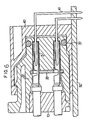
- Figure 6 is a longitudinal sectional view illustrating an example of a particular application of the embodiment shown in Figure 1;
- Figure 7 is a perspective view illustrating another embodiment of the holding plate according to the present invention.
- Figure 8 is a perspective view illustrating a further embodiment of the holding plate according to the present invention.
- Fig. 1 shows a particular embodiment of the present invention.
- the connector shown is of the female type and is connected to a tab 41 (see Fig. 6) of a male type connector 40 provided on a printed circuit board 50 in particular use.
- the connector assembly according to the present invention is not limited to this structure and may also be formed, for example, by a pair of male and female connectors connected to each other. Since the type of connector (i.e., male or female) is determined in part by the shape of the contact thereof and is not essential, the present invention can be applied to connector assemblies of either type.
- reference numeral 1 denotes an electrical wire which is terminated by a conductive contact 2.
- a conductive contact 2 typically, a cylindrical contact having a rectangular cross-section is used, but the present invention is not limited to this configuration, as previously described.
- Reference numeral 30 denotes an insulative housing which has a cavity for receiving a rubber bush to be described later and a holding plate 20.
- a hole 36 is provided for receiving the contact 2 which is passed through the rubber bush and the holding plate. The contact is received in the hole in the manner as shown in Figs. 2, 3 and 6 to be described hereinafter.
- Reference numeral 10 denotes a rubber bush having hole portions 11 through each of which the wire 1 passes.
- Each hole portion includes a recess 11A provided in one surface of the rubber bush, and a through hole 11B which extends from the bottom of the recess to the other surface of the rubber bush.
- the recess is preferably provided with an opening of the shape corresponding to that of the cross-section of the above-mentioned contact.
- the contact which terminates the wire is first inserted into the recess of the rubber bush, and is then passed through and expands the through hole. At this point, the orientation of the contact is determined since the shape of the recess opening corresponds to that of the cross-section of the contact. In addition, the respective wires are sealed by the through holes of the hole portions.
- the rubber bush is sealably fixed within the cavity of the housing by fixing means, which is exemplified by an engaging projection 14 formed on the rubber bush, and an engaging grove 31 formed in the housing.
- Reference numeral 20 denotes the holding plate having hole portions 21 through each of which the contacts 2 of the terminated wire are passed subsequent to passing through the rubber bush.
- the hole portion 21 of the holding plate is integrally formed by a portion through which the contact is inserted and a portion with which the conductive contact 2 is latchably engaged. More particularly, each hole portion includes a first through hole 21A having an opening of such size that the contact can be inserted therethrough, and a second through hole 21B having an opening smaller than that of the first through hole.
- each wire is inserted through the first through hole (in the embodiment shown, the contact is received in the hole 36, which communicates with the exterior of the housing from the bottom of the cavity, after it passes through the holding plate) and the holding plate is then slidably displaced. This causes the junction between the contact and the wire to be engaged in the second through hole (see Figs. 2 through 5).
- a spring member 22 is provided, for example, at one side edge of the holding plate so that the plate can be locked in the housing. This spring member locks the holding plate by urging it against the inner wall of the housing opposite the spring member within the cavity of the housing.
- This locking means may also be realized by a latch 23, as shown in Fig. 8, provided on one side edge of the holding plate and a corresponding notch provided in the inner wall of the housing.
- a tool 39 for moving the holding plate is inserted into a through hole 34 having exterior access provided in the housing, and a notch 24 provided at one side edge of the plate is engaged with the tool to displace the plate (see Fig. 2).
- the holding plate may also be displaced by other means.
- the circumferential side surface of the above-mentioned contact may be formed as a cam surface, so that the holding plate is displaced as the contact is inserted into the through hole of the holding plate.
- the displacement of the above-mentioned holding plate is indicated, for example, by bringing a pole 25 which is made to project from the holding plate into alignment with an indicator hole 35 formed in the housing.
- the indicator hole consists of a through hole portion 35A and a blind hole portion 35B.
- the pole moves into the blind hole portion and thereby becomes invisible from outside. This allows the movement of the plate to be identified from the outside.
- reference numeral 33 denotes means for displacing the holding plate only in a predetermined direction within the housing. More specifically, this means comprises a stopper for preventing the movement of the holding plate in any direction which crosses the direction along the surface of the plate.
- Figs. 2 and 3 show the procedure according to which the contact is engaged with the holding plate and is received in the contact holding hole 36 in the housing in the first embodiment of the present invention shown in Fig. 1.
- a tool 39 for moving the holding plate is first inserted into the through hole 34 provided in the housing for allowing the tool to pass therethrough. Next, the tool is engaged with the notch 24 provided at the side edge of the holding plate, to slide the plate.
- the spring member of the holding plate acts to return the holding plate to its initial position, as shown in Fig. 3.
- the junction between the contact and the wire is engaged in the second through hole 21B in the holding plate, which thereby holds the contact received in the housing. Release of the contact is similarly effected by movement of the holding plate by the tool 39 in the same manner as effecting insertion.
- Figs. 4 and 5 show a state wherein the contact 2 of the wire is engaged with the holding plate. More particularly, Fig. 4 shows a state wherein the contact is inserted through the first through hole 21A of the hole portion, while Fig. 5 shows a state wherein the holding plate is displaced (slid) to bring the junction (the constricted portion) between the wire and the contact into engagement in the second through hole 21B of the hole portion.
- Fig. 6 is a longitudinal sectional view illustrating a connector assembly, according to the present invention, which is connected with a male type connector provided on a printed circuit board.
- reference numeral 50 denotes a printed circuit board; 41, a tab-like terminal (contact); 40, a housing of the male type connector; and 37, a waterproof O-ring.
- the connector assembly according to the present invention is used as a female type connector in this case.
- the contact at the terminated end of the wire can be inserted through the rubber bush without using a special tool.
- the fixed direction of insertion can be maintained by matching the shape of a noncircular contact with that of the recess of the rubber bush, and the wire passed through the rubber bush is sufficiently sealed by the through hole, which communicates with the above-mentioned recess.
- the contacts at the ends of the wires are respectively inserted or released through the hole portions of the holding plate when the plate is slid by a tool.
- the contacts are then engaged with and held in the plate upon removal of the tool. This results in significant improvement in the efficiency of the assembly operation.
- the present invention can be widely applied.
- the contact of the present invention is formed in a particular arrangement as a cylindrical contact having a rectangular cross-section, it can be connected with a flat tab terminal (contact) provided on a printed circuit board.
- the plate shown may be disk-shaped (therefore, the housing for receiving this plate has a cavity with a similar circular opening).
- a contact 2 ⁇ of each wire is first inserted through a hole portion 11 ⁇ of this plate. Since the contact has a flange 2 ⁇ A, the hole portion has a diameter which allows this flange to pass therethrough. After each wire is inserted through the through hole in the plate shown, the plate is pivoted to bring each wire into engagement with one of the hole portions in the plate.
Description
- The present invention relates to an electrical connector and more particularly to a connector having a water seal.
- Electronics technology has been rapidly developed in recent years and its applications have been significantly increased with the advent of compact, high-density electronic components. Thus, printed circuit boards and other devices which incorporate a great number of such electronic components have been utilized in different manners and in various forms.
- Connectors for connecting printed circuit boards to each other or connecting a printed circuit board to another electronic component have been also developed in various forms, in accordance with their particular applications.
- For example, in connectors of this type for water sealed applications, each of the wires terminated by contacts is typically inserted through a rubber bush, using a special tool, in advance, and the resultant assembly in a sealed state is received within a cavity of a housing. It therefore takes a considerable period of time to assemble the wires in a connector, and more convenient techniques have been needed to accomplish this.
- A connector of this type, in which individual rubber bushes are provided for sealing each contact, is shown in US-A-3573720, each contact and bush engaging an individual passage in the body of the housing. Additionally, US-A-3573720 shows an external locking plate for the contact and bush assemblies, the locking plate being movable between a locking position, in which the contact and bush assemblies are retained in the housing, and a release position in which individual contact and bush assemblies can be pulled out through a respective hole in the locking plate. The construction of US-A-3573720, with individual contacts, bushes and housing passages, involves an external locking plate, although this construction has disadvantages firstly in view of the assembly time involved as discussed in the previous paragraph, and because an external locking plate carries the risk of inadvertent movement or damage, together with the fact that deliberate movement requires activity at the end of the connector at which wires enter, so that care is required not to damage the wire insulation.
- According to the invention, there is provided a connector assembly to a wire terminated by a conductive contact, comprising:
- an insulative housing having a cavity extending into a front surface thereof and a hole communicating with said cavity and extending into a rear portion of said housing for receipt of said contact; sealing means extending exteriorly on the housing around its rear portion for providing a seal when said housing is inserted into a connector header;
- a rubber bush sealably received in said housing cavity and having a hole aligned with said hole in said housing for sealed receipt of said contact;
- a movable retention member supported by said housing within said housing cavity between said hole and said bush and having a latching portion for latching engagement with said contact for retaining said contact in said hole; and
- an opening extending into said housing through said rear portion thereof and communicating with said retention member to permit the entry of a tool to engage said movable retention member so as to move said latching portion away from the latching position and thereby allow withdrawal of said contact from said housing hole.
- By way of example, embodiments of a connector assembly according to the present invention will now be described with reference to the accompanying drawings, in which:
- Figure 1 is an exploded perspective view illustrating a connector assembly according to a particular embodiment of the present invention;
- Figures 2 and 3 are respectively fragmented cross-sectional views illustrating an assembly procedure employed in the embodiment of Figure 1;
- Figures 4 and 5 are respectively perspective views illustrating various components in the assembly procedure shown in Figures 2 and 3;
- Figure 6 is a longitudinal sectional view illustrating an example of a particular application of the embodiment shown in Figure 1;
- Figure 7 is a perspective view illustrating another embodiment of the holding plate according to the present invention; and
- Figure 8 is a perspective view illustrating a further embodiment of the holding plate according to the present invention.
- Fig. 1 shows a particular embodiment of the present invention. The connector shown is of the female type and is connected to a tab 41 (see Fig. 6) of a
male type connector 40 provided on a printedcircuit board 50 in particular use. It is to be noted that the connector assembly according to the present invention is not limited to this structure and may also be formed, for example, by a pair of male and female connectors connected to each other. Since the type of connector (i.e., male or female) is determined in part by the shape of the contact thereof and is not essential, the present invention can be applied to connector assemblies of either type. - In Fig. 1, reference numeral 1 denotes an electrical wire which is terminated by a
conductive contact 2. Typically, a cylindrical contact having a rectangular cross-section is used, but the present invention is not limited to this configuration, as previously described. -
Reference numeral 30 denotes an insulative housing which has a cavity for receiving a rubber bush to be described later and aholding plate 20. Ahole 36 is provided for receiving thecontact 2 which is passed through the rubber bush and the holding plate. The contact is received in the hole in the manner as shown in Figs. 2, 3 and 6 to be described hereinafter. -
Reference numeral 10 denotes a rubber bush having hole portions 11 through each of which the wire 1 passes. Each hole portion includes arecess 11A provided in one surface of the rubber bush, and a through hole 11B which extends from the bottom of the recess to the other surface of the rubber bush. The recess is preferably provided with an opening of the shape corresponding to that of the cross-section of the above-mentioned contact. - The contact which terminates the wire is first inserted into the recess of the rubber bush, and is then passed through and expands the through hole. At this point, the orientation of the contact is determined since the shape of the recess opening corresponds to that of the cross-section of the contact. In addition, the respective wires are sealed by the through holes of the hole portions.
- The rubber bush is sealably fixed within the cavity of the housing by fixing means, which is exemplified by an
engaging projection 14 formed on the rubber bush, and anengaging grove 31 formed in the housing. -
Reference numeral 20 denotes the holding plate havinghole portions 21 through each of which thecontacts 2 of the terminated wire are passed subsequent to passing through the rubber bush. - The
hole portion 21 of the holding plate is integrally formed by a portion through which the contact is inserted and a portion with which theconductive contact 2 is latchably engaged. More particularly, each hole portion includes a first throughhole 21A having an opening of such size that the contact can be inserted therethrough, and a second throughhole 21B having an opening smaller than that of the first through hole. - The contact of each wire is inserted through the first through hole (in the embodiment shown, the contact is received in the
hole 36, which communicates with the exterior of the housing from the bottom of the cavity, after it passes through the holding plate) and the holding plate is then slidably displaced. This causes the junction between the contact and the wire to be engaged in the second through hole (see Figs. 2 through 5). - In the embodiment shown in Fig. 1, a
spring member 22 is provided, for example, at one side edge of the holding plate so that the plate can be locked in the housing. This spring member locks the holding plate by urging it against the inner wall of the housing opposite the spring member within the cavity of the housing. - This locking means may also be realized by a
latch 23, as shown in Fig. 8, provided on one side edge of the holding plate and a corresponding notch provided in the inner wall of the housing. - In order to render the holding plate slidably movable after it has been temporarily locked by the above-mentioned locking means, a tool 39 (see Fig. 2) for moving the holding plate is inserted into a
through hole 34 having exterior access provided in the housing, and anotch 24 provided at one side edge of the plate is engaged with the tool to displace the plate (see Fig. 2). - The holding plate may also be displaced by other means. For example, the circumferential side surface of the above-mentioned contact may be formed as a cam surface, so that the holding plate is displaced as the contact is inserted into the through hole of the holding plate.
- The displacement of the above-mentioned holding plate is indicated, for example, by bringing a
pole 25 which is made to project from the holding plate into alignment with anindicator hole 35 formed in the housing. The indicator hole consists of a throughhole portion 35A and ablind hole portion 35B. As the holding plate is displaced, the pole moves into the blind hole portion and thereby becomes invisible from outside. This allows the movement of the plate to be identified from the outside. - In Fig. 1,
reference numeral 33 denotes means for displacing the holding plate only in a predetermined direction within the housing. More specifically, this means comprises a stopper for preventing the movement of the holding plate in any direction which crosses the direction along the surface of the plate. - Figs. 2 and 3 show the procedure according to which the contact is engaged with the holding plate and is received in the
contact holding hole 36 in the housing in the first embodiment of the present invention shown in Fig. 1. - As shown in Fig. 2, a
tool 39 for moving the holding plate is first inserted into the throughhole 34 provided in the housing for allowing the tool to pass therethrough. Next, the tool is engaged with thenotch 24 provided at the side edge of the holding plate, to slide the plate. - At this point, since the first through
hole 21A of the holding plate is aligned with thehole 36 of the housing, the contact extends throughhole 21A. - When the
tool 39 is withdrawn, the spring member of the holding plate acts to return the holding plate to its initial position, as shown in Fig. 3. The junction between the contact and the wire is engaged in the second throughhole 21B in the holding plate, which thereby holds the contact received in the housing. Release of the contact is similarly effected by movement of the holding plate by thetool 39 in the same manner as effecting insertion. - Figs. 4 and 5 show a state wherein the
contact 2 of the wire is engaged with the holding plate. More particularly, Fig. 4 shows a state wherein the contact is inserted through the first throughhole 21A of the hole portion, while Fig. 5 shows a state wherein the holding plate is displaced (slid) to bring the junction (the constricted portion) between the wire and the contact into engagement in the second throughhole 21B of the hole portion. - Fig. 6 is a longitudinal sectional view illustrating a connector assembly, according to the present invention, which is connected with a male type connector provided on a printed circuit board.
- In this drawing figure,
reference numeral 50 denotes a printed circuit board; 41, a tab-like terminal (contact); 40, a housing of the male type connector; and 37, a waterproof O-ring. - The connector assembly according to the present invention is used as a female type connector in this case.
- The construction of the connector assembly according to the present invention has been described above and provides the following desirable advantages.
- In the connector according to the present invention, the contact at the terminated end of the wire can be inserted through the rubber bush without using a special tool. In addition, the fixed direction of insertion can be maintained by matching the shape of a noncircular contact with that of the recess of the rubber bush, and the wire passed through the rubber bush is sufficiently sealed by the through hole, which communicates with the above-mentioned recess.
- With the holding plate according to the present invention, the contacts at the ends of the wires are respectively inserted or released through the hole portions of the holding plate when the plate is slid by a tool. The contacts are then engaged with and held in the plate upon removal of the tool. This results in significant improvement in the efficiency of the assembly operation.
- The present invention can be widely applied. For example, since the contact of the present invention is formed in a particular arrangement as a cylindrical contact having a rectangular cross-section, it can be connected with a flat tab terminal (contact) provided on a printed circuit board.
- Having described the preferred embodiment of the present invention it should be appreciated that variations may be made. For example, as shown in Fig. 7 the plate shown may be disk-shaped (therefore, the housing for receiving this plate has a cavity with a similar circular opening). A contact 2ʹ of each wire is first inserted through a hole portion 11ʹ of this plate. Since the contact has a flange 2ʹ A, the hole portion has a diameter which allows this flange to pass therethrough. After each wire is inserted through the through hole in the plate shown, the plate is pivoted to bring each wire into engagement with one of the hole portions in the plate.
Claims (10)
an insulative housing (30) having a cavity extending into a front surface thereof and a hole (36) communicating with said cavity and extending into a rear portion of said housing for receipt of said contact; sealing means (37) extending exteriorly on the housing around its rear portion for providing a seal when said housing (30) is inserted into a connector header (40);
a rubber bush (10) sealably received in said housing cavity and having a hole (11) aligned with said hole (36) in said housing for sealed receipt of said contact;
a movable retention member (20) supported by said housing within said housing cavity between said hole (36) and said bush (10) and having a latching portion (21B) for latching engagement with said contact for retaining said contact in said hole (36); and
an opening (34) extending into said housing (30) through said rear portion thereof and communicating with said retention member (20) to permit the entry of a tool (39) to engage said movable retention member so as to move said latching portion (21B) away from the latching position and thereby allow withdrawal of said contact (2) from said housing hole (36).
Applications Claiming Priority (4)
| Application Number | Priority Date | Filing Date | Title |
|---|---|---|---|
| JP184351/85 | 1985-08-23 | ||
| JP18435285A JPS6247979A (en) | 1985-08-23 | 1985-08-23 | Connector |
| JP184352/85 | 1985-08-23 | ||
| JP18435185A JPS6247983A (en) | 1985-08-23 | 1985-08-23 | Connector assembly |
Publications (3)
| Publication Number | Publication Date |
|---|---|
| EP0214794A2 EP0214794A2 (en) | 1987-03-18 |
| EP0214794A3 EP0214794A3 (en) | 1988-09-21 |
| EP0214794B1 true EP0214794B1 (en) | 1991-01-02 |
Family
ID=26502450
Family Applications (1)
| Application Number | Title | Priority Date | Filing Date |
|---|---|---|---|
| EP86306480A Expired - Lifetime EP0214794B1 (en) | 1985-08-23 | 1986-08-21 | Connector assembly |
Country Status (5)
| Country | Link |
|---|---|
| US (1) | US4721478A (en) |
| EP (1) | EP0214794B1 (en) |
| AU (1) | AU573455B2 (en) |
| CA (1) | CA1290041C (en) |
| DE (1) | DE3676398D1 (en) |
Families Citing this family (23)
| Publication number | Priority date | Publication date | Assignee | Title |
|---|---|---|---|---|
| JPH0646067Y2 (en) * | 1987-04-13 | 1994-11-24 | 矢崎総業株式会社 | Waterproof connector |
| DE3725668A1 (en) * | 1987-08-03 | 1989-02-16 | Bosch Gmbh Robert | MULTIPOLE CONNECTOR |
| DE8713932U1 (en) * | 1987-10-16 | 1988-01-14 | Du Pont De Nemours (Nederland) B.V., Dordrecht, Nl | |
| JPH01197979A (en) * | 1988-01-31 | 1989-08-09 | Amp Inc | Double-lock connector |
| FR2632459A1 (en) * | 1988-06-03 | 1989-12-08 | Loire Electronique | CONNECTION BASE, PARTICULARLY CONNECTION FOR COAXIAL SOCKET, FACADE MOUNTING |
| JPH0690940B2 (en) * | 1989-05-25 | 1994-11-14 | 矢崎総業株式会社 | Electrical connector with double locking structure for terminal fittings |
| US5203722A (en) * | 1990-09-28 | 1993-04-20 | Amp Incorporated | Double-lock electrical connector |
| JPH05266941A (en) * | 1992-03-19 | 1993-10-15 | Amp Japan Ltd | Waterproof connector |
| FR2714536B1 (en) * | 1993-12-27 | 1996-01-19 | Cinch Connecteurs Sa | Improvements to the components of electrical connector housings. |
| US5554055A (en) * | 1994-08-31 | 1996-09-10 | Thomas & Betts Corporation | Electrical connector employing dual locking contact retention |
| JP3106285B2 (en) * | 1995-05-12 | 2000-11-06 | 矢崎総業株式会社 | Cover-integrated insulation displacement connector |
| GB9514797D0 (en) * | 1995-07-19 | 1995-09-20 | Amp Gmbh | Electrical connector with two step positive contact retention |
| FR2738081B1 (en) * | 1995-08-22 | 1997-09-26 | Cinch Connecteurs Sa | ELECTRICAL CONNECTOR |
| DE19741949C2 (en) * | 1997-09-23 | 2002-04-25 | Framatome Connectors Int | Connector with a housing with secondary locking |
| US6061249A (en) * | 1997-11-12 | 2000-05-09 | Ericsson Inc. | Sealing system and method for sealing circuit card connection sites |
| US5967859A (en) * | 1997-12-10 | 1999-10-19 | Molex Incorporated | Electrical connector assembly with terminal retainer system |
| US6171154B1 (en) * | 1998-10-29 | 2001-01-09 | Hon Hai Precision Ind. Co., Ltd. | Device bay connector |
| JP2000208200A (en) * | 1999-01-13 | 2000-07-28 | Yazaki Corp | Waterproof connector |
| USD432498S (en) * | 1999-01-28 | 2000-10-24 | Japan Solderless Terminal Mfg. Co., Ltd. | Connector for printed circuit boards |
| JP2001203033A (en) | 2000-01-20 | 2001-07-27 | Thomas & Betts Corp <T&B> | Connector |
| JP2002100433A (en) | 2000-07-17 | 2002-04-05 | Yazaki Corp | Connector with retainer |
| DE102012223431A1 (en) * | 2012-12-17 | 2014-06-18 | Robert Bosch Gmbh | Housing for an electric machine with a seal |
| USD966888S1 (en) * | 2020-03-05 | 2022-10-18 | Kimberly-Clark Worldwide, Inc. | Lid |
Family Cites Families (19)
| Publication number | Priority date | Publication date | Assignee | Title |
|---|---|---|---|---|
| US2881406A (en) * | 1955-06-20 | 1959-04-07 | Cannon Electric Co | Moisture seal for connectors |
| US2903668A (en) * | 1955-09-26 | 1959-09-08 | Burndy Corp | Multiple connector |
| GB1184250A (en) * | 1967-11-18 | 1970-03-11 | Amp Inc | Sealing Arrangement for Multiple Contacts |
| US3573720A (en) * | 1969-01-07 | 1971-04-06 | Amp Inc | Electrical connector |
| DE2630145A1 (en) * | 1976-07-05 | 1978-01-19 | Schaltbau Gmbh | HOLDER FOR PLUG ELEMENTS |
| US4150866A (en) * | 1977-08-26 | 1979-04-24 | Amp Incorporated | Environmentally sealed connector |
| US4131331A (en) * | 1977-11-18 | 1978-12-26 | Clemar Mfg. Corp. | Waterproof electrical connector |
| US4311355A (en) * | 1978-10-23 | 1982-01-19 | General Motors Corporation | Weatherproof electrical connector |
| US4214472A (en) * | 1979-01-22 | 1980-07-29 | Ford Motor Company | Exhaust gas oxygen sensor and electrical connector arrangement |
| US4227762A (en) * | 1979-07-30 | 1980-10-14 | Vaughn Corporation | Electrical connector assembly with latching bar |
| US4253718A (en) * | 1979-09-04 | 1981-03-03 | General Motors Corporation | Electrical connector |
| US4473267A (en) * | 1981-03-12 | 1984-09-25 | Thomas & Betts Corporation | Electrical connector for use in adverse environments |
| US4406507A (en) * | 1981-06-30 | 1983-09-27 | The Bendix Corporation | Electrical connector insert |
| US4520423A (en) * | 1982-10-25 | 1985-05-28 | Rockwell International Corporation | Tamperproof, moisture proof readout enclosure |
| FR2544559B1 (en) * | 1982-11-09 | 1985-10-25 | Labinal | WATERPROOF ELECTRICAL CONNECTOR |
| GB2135140B (en) * | 1983-02-15 | 1986-09-10 | Amp Inc | Electrical conductor sealing member |
| US4588242A (en) * | 1983-07-06 | 1986-05-13 | Amp Incorporated | Sealed electrical connector |
| JPS6019157U (en) * | 1983-07-15 | 1985-02-08 | 住友電装株式会社 | waterproof connector |
| US4611872A (en) * | 1983-09-21 | 1986-09-16 | Tokai Electric Wire Company Limited | Water-proof connector |
-
1986
- 1986-08-15 US US06/896,894 patent/US4721478A/en not_active Expired - Lifetime
- 1986-08-18 AU AU61563/86A patent/AU573455B2/en not_active Ceased
- 1986-08-21 EP EP86306480A patent/EP0214794B1/en not_active Expired - Lifetime
- 1986-08-21 DE DE8686306480T patent/DE3676398D1/en not_active Expired - Fee Related
- 1986-08-22 CA CA000516665A patent/CA1290041C/en not_active Expired - Lifetime
Also Published As
| Publication number | Publication date |
|---|---|
| US4721478A (en) | 1988-01-26 |
| AU6156386A (en) | 1987-02-26 |
| CA1290041C (en) | 1991-10-01 |
| AU573455B2 (en) | 1988-06-09 |
| DE3676398D1 (en) | 1991-02-07 |
| EP0214794A2 (en) | 1987-03-18 |
| EP0214794A3 (en) | 1988-09-21 |
Similar Documents
| Publication | Publication Date | Title |
|---|---|---|
| EP0214794B1 (en) | Connector assembly | |
| EP0599165B1 (en) | Electrical connector with terminal position assurance system | |
| US4797116A (en) | Electrical connector having a movable contact guide and lance-maintaining member | |
| JP3995174B2 (en) | Electrical connector | |
| JPS59148287A (en) | Connector | |
| US20070099504A1 (en) | Electrical connector assembly having improved locking mechanism | |
| US4900263A (en) | Positive connector latch | |
| KR940016993A (en) | Electrical Connector Assembly With Terminal Alignment System | |
| US4452501A (en) | Electrical connector with latch terminal | |
| US5160279A (en) | Double lock connector | |
| US5037314A (en) | Connecting assembly for printed circuit boards | |
| US5643016A (en) | Electrical connector assembly with contact retention and removal system | |
| US3763458A (en) | Terminal retaining connector block | |
| US4445742A (en) | Electrical cable connector | |
| JP2729561B2 (en) | connector | |
| CN212209893U (en) | Connector with a locking member | |
| US5910031A (en) | Wire to board connector | |
| US5564950A (en) | Double-sided connector for connection to an electrical cable | |
| KR20010091052A (en) | Electrical connector | |
| US6830485B2 (en) | Electrical connector with a terminal pin stabilizing plate | |
| US5928014A (en) | Electrical connector having a pair of connector housings | |
| EP1006380B1 (en) | Electrical and/or optical connector | |
| CA2346757C (en) | Plug connector | |
| US6328606B1 (en) | High density electrical connector system | |
| JPH1050379A (en) | Electric connector |
Legal Events
| Date | Code | Title | Description |
|---|---|---|---|
| PUAI | Public reference made under article 153(3) epc to a published international application that has entered the european phase |
Free format text: ORIGINAL CODE: 0009012 |
|
| AK | Designated contracting states |
Kind code of ref document: A2 Designated state(s): BE CH DE FR GB IT LI NL SE |
|
| PUAL | Search report despatched |
Free format text: ORIGINAL CODE: 0009013 |
|
| AK | Designated contracting states |
Kind code of ref document: A3 Designated state(s): BE CH DE FR GB IT LI NL SE |
|
| 17P | Request for examination filed |
Effective date: 19890303 |
|
| 17Q | First examination report despatched |
Effective date: 19890907 |
|
| GRAA | (expected) grant |
Free format text: ORIGINAL CODE: 0009210 |
|
| AK | Designated contracting states |
Kind code of ref document: B1 Designated state(s): BE CH DE FR GB IT LI NL SE |
|
| REF | Corresponds to: |
Ref document number: 3676398 Country of ref document: DE Date of ref document: 19910207 |
|
| ITF | It: translation for a ep patent filed |
Owner name: SOCIETA' ITALIANA BREVETTI S.P.A. |
|
| ET | Fr: translation filed | ||
| PGFP | Annual fee paid to national office [announced via postgrant information from national office to epo] |
Ref country code: FR Payment date: 19910712 Year of fee payment: 6 |
|
| PGFP | Annual fee paid to national office [announced via postgrant information from national office to epo] |
Ref country code: DE Payment date: 19910716 Year of fee payment: 6 Ref country code: CH Payment date: 19910716 Year of fee payment: 6 |
|
| PGFP | Annual fee paid to national office [announced via postgrant information from national office to epo] |
Ref country code: SE Payment date: 19910718 Year of fee payment: 6 |
|
| PGFP | Annual fee paid to national office [announced via postgrant information from national office to epo] |
Ref country code: BE Payment date: 19910726 Year of fee payment: 6 |
|
| PGFP | Annual fee paid to national office [announced via postgrant information from national office to epo] |
Ref country code: GB Payment date: 19910731 Year of fee payment: 6 |
|
| PGFP | Annual fee paid to national office [announced via postgrant information from national office to epo] |
Ref country code: NL Payment date: 19910831 Year of fee payment: 6 |
|
| PLBE | No opposition filed within time limit |
Free format text: ORIGINAL CODE: 0009261 |
|
| STAA | Information on the status of an ep patent application or granted ep patent |
Free format text: STATUS: NO OPPOSITION FILED WITHIN TIME LIMIT |
|
| 26N | No opposition filed | ||
| PG25 | Lapsed in a contracting state [announced via postgrant information from national office to epo] |
Ref country code: GB Effective date: 19920821 |
|
| PG25 | Lapsed in a contracting state [announced via postgrant information from national office to epo] |
Ref country code: SE Effective date: 19920822 |
|
| PG25 | Lapsed in a contracting state [announced via postgrant information from national office to epo] |
Ref country code: LI Effective date: 19920831 Ref country code: CH Effective date: 19920831 Ref country code: BE Effective date: 19920831 |
|
| BERE | Be: lapsed |
Owner name: THOMAS & BETTS CORP. Effective date: 19920831 |
|
| PG25 | Lapsed in a contracting state [announced via postgrant information from national office to epo] |
Ref country code: NL Effective date: 19930301 |
|
| NLV4 | Nl: lapsed or anulled due to non-payment of the annual fee | ||
| GBPC | Gb: european patent ceased through non-payment of renewal fee |
Effective date: 19920821 |
|
| PG25 | Lapsed in a contracting state [announced via postgrant information from national office to epo] |
Ref country code: FR Effective date: 19930430 |
|
| REG | Reference to a national code |
Ref country code: CH Ref legal event code: PL |
|
| PG25 | Lapsed in a contracting state [announced via postgrant information from national office to epo] |
Ref country code: DE Effective date: 19930501 |
|
| REG | Reference to a national code |
Ref country code: FR Ref legal event code: ST |
|
| EUG | Se: european patent has lapsed |
Ref document number: 86306480.4 Effective date: 19930307 |
|
| PG25 | Lapsed in a contracting state [announced via postgrant information from national office to epo] |
Ref country code: IT Free format text: LAPSE BECAUSE OF NON-PAYMENT OF DUE FEES;WARNING: LAPSES OF ITALIAN PATENTS WITH EFFECTIVE DATE BEFORE 2007 MAY HAVE OCCURRED AT ANY TIME BEFORE 2007. THE CORRECT EFFECTIVE DATE MAY BE DIFFERENT FROM THE ONE RECORDED. Effective date: 20050821 |