EP0214767A2 - Kraftstoffladungsmittel - Google Patents
Kraftstoffladungsmittel Download PDFInfo
- Publication number
- EP0214767A2 EP0214767A2 EP86306171A EP86306171A EP0214767A2 EP 0214767 A2 EP0214767 A2 EP 0214767A2 EP 86306171 A EP86306171 A EP 86306171A EP 86306171 A EP86306171 A EP 86306171A EP 0214767 A2 EP0214767 A2 EP 0214767A2
- Authority
- EP
- European Patent Office
- Prior art keywords
- edge region
- aircraft
- rearward
- fuel
- wing
- Prior art date
- Legal status (The legal status is an assumption and is not a legal conclusion. Google has not performed a legal analysis and makes no representation as to the accuracy of the status listed.)
- Granted
Links
Images


Classifications
-
- B—PERFORMING OPERATIONS; TRANSPORTING
- B64—AIRCRAFT; AVIATION; COSMONAUTICS
- B64D—EQUIPMENT FOR FITTING IN OR TO AIRCRAFT; FLIGHT SUITS; PARACHUTES; ARRANGEMENT OR MOUNTING OF POWER PLANTS OR PROPULSION TRANSMISSIONS IN AIRCRAFT
- B64D37/00—Arrangements in connection with fuel supply for power plant
- B64D37/02—Tanks
- B64D37/04—Arrangement thereof in or on aircraft
Definitions
- This invention relates to collapsible fuel storage means for storing fuel on an aircraft.
- a disadvantage of this arrangement is that when the tank is expanded, the wetted area of the aircraft is increased thus increasing the drag attributable to the fuel tank. Moreover the tank when expanded does not blend smoothly with the aircraft structure, thus giving rise to slots which are detrimental to the airflow over the wing. In addition, suction loads on the wall panel are reacted by the volume of fuel within the tank and this may disturb the proper delivery of fuel from the tank.
- an aircraft including a fuselage portion, a wing portion connected thereto and expandable fuel storage means disposed adjacent the intersection of said wing portion and said fuselage portion, said fuel storage means having external surface-defining means which includes spanwise spaced inner and outer edge regions extending in a generally chordwise direction, said inner edge region extending alongside the fuselage portion and said outer edge region being attached to said wing portion to allow movement of the surface-defining means between an empty position in which it lies generally flush with the surrounding surface of the wing portion and a fuel storing position in which it lies at an acute angle to said surrounding surface forming a fillet region between the wing portion and the fuselage portion.
- the external surface-defining means when the external surface-defining means is in a fuel storing position the wetted area of the aircraft is decreased, rather than increased. In addition, the external surface-defining means moves to its fuel storing position without creating large gaps or slots.
- the external surface-defining means is preferably of trapezoidal planform having an inner edge region lying generally alongside the body portion, an outer edge region extending generally chordwise, a forward edge region extending along a leading edge region of the wing portion and a rearward edge region extending along a trailing edge region of the wing portion.
- the trapezoidal external surface-defining means preferably comprises a forward resiliently deformable panel element of generally triangular planform and a rearward resiliently deformable panel element of generally rectangular planform, the forward panel element having an inner edge region extending generally alongside the fuselage portion, an outer edge region attached to said leading edge region for hingeing movement, and a rearward edge region slidably coupled to a forward edge region of the rearward panel element.
- a resiliently flexible beam element of variable effective length attached to and extending along the inner edge regions of said forward and rearward panel elements and being anchored to the wing portion at forward and rearward anchorage points.
- the surface of said fuselage portion over which the inner edge region of the external surface-defining means passes when moving between the empty and the fuel storing position is of concave form to prevent a gap.
- the fuel storage means includes retraction means operable to draw the external surface-defining means from a fuel storing position towards its empty position.
- the retraction means preferably comprises a plurality of tie members attached to the external surface-defining means at spaced locations along its inner edge region.
- Each of said tie members is preferably caused to retract at a predetermined rate relative to the remainer of said tie members thereby to ensure that said inner edge region adopts a predetermined profile when moving between the fuel storage and the empty position.
- the required relative movement of the various tie members may advantageously be achieved by employing a windlass device comprising winding portions for each tie member of predetermined diameter selected having regard to the desired relative rate of retraction.
- the windlass device may be driven by means of a flexible drive element wrapped around a driving portion of the windlass and having a free end attached to a hydraulic ram for effecting longitudinal movement.
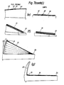
- FIG. 1 to 4 there is illustrated a jet-propelled fighter aircraft incorporating a collapsible fuel storage system.
- the aircraft includes a main fuselage 10 with port and starboard wings 11 each merging with the fuselage at an intermediate wing root portion 12.
- the fuel storage system comprises port and starboard collapsible fuel tanks generally designated 13 and each located on the upper surface of the associated wing root portion.
- the system is illustrated with the port fuel tank shown in a fully expanded condition and the starboard fuel tank in an empty condition.
- the collapsible fuel tank effectively forms a non-structural fillet extending between the wing portion and the associated edge region of the fuselage 10 and therefore that the incremental wetted area of the tank in its fully expanded condition is negative compared to when it is in its fully collapsed condition.
- the tank comprises a forward panel 14 of generally triangular planform hingedly attached to the upper surface of the leading edge region of the wing by means of a piano hinge arrangment for hinged movement about a leading edge region 15 and, lying immediately rearwardly of the forward panel 14, a rearward panel 16 of generally rectangular planform having spaced parallel inner and outer side regions 17 and 18 and being hingedly attached to the generally curved upper surface of the wing by means of a piano hinge arrangement for hingeing movement about the outer edge region 18.
- Each panel is formed of a resiliently flexible material and in the illustrated embodiment comprises a honeycomb core sheathed with carbon fibre reinforced plastics material.
- the external profile of the tank as it is caused to move from an empty to a fuel storing condition is maintained relatively smoothly curved by means of a resiliently flexible profile control beam 19 having a sliding joint 25 intermediate its ends which is disposed generally in line with the abutting edges of the forward panel and the rearward panel.
- the profile of the intermediate region between the forward and rearward panels is maintained during movement to a fuel storing condition by means of three spigot pins 20 secured to the rearward edge of the forward panel 14 and sliding in guides (not shown) provided in the core of the rearward panel 16.
- the forward end of the control beam 19 is pivotably attached to a forward part of the wing by a bracket 21 allowing rotation only (see Figure 7 (c)) whilst the rearward end of the control beam is connected to the fuselage side by a spherical roller track arrangement 22 which allows both longitudinal and rotational movement of the end of the control beam 19.
- the rearward panel is hingedly attached by means of a piano hinge to a curved surface, and in order to minimise the forces in the plane of the panel which will be increasingly induced as it hinges upwards away from the wing surface, a sliding joint (not shown) is provided at the connection between the piano hinge and the panel.
- Two fixed locations for the sliding joint between the panel and the piano hinge are provided, at the rearward end of the hinge and towards the forward end. These two points are specially selected to minimise the extent of the movement and also to ensure that there is no relative spanwise movement between the forward and the rearward panel on movement to the fuel storing condition.
- the joint between the two panels does nevertheless have to allow for chordwise relative displacement and fairing plates 24 are attached to the forward panel upper and lower surfaces and slide on the aft panel providing an aerodynamic fairing and seal for the joint.
- Flexible fairing plates 26 are also provided between the leading edge of the forward panel and the adjacent upper surface of the wing, between the outboard edge region of the rearward panel and the associated upper surface of the wing, and between the rearward edge edge portion of the rearward panel and the adjacent upper surface of the wing flap 27, in each case to provide aerodynamic surface continuity.
- the fairing extends from the rearward edge of the rearward panel to be carried in a roller track arrangement 28 provided in the flap so that on deflection of the flap the fairing still blends smoothly with the flap and the wing as shown in Figure 7(b).
- the surface region 23 of the fuselage side portion over which the inner edge region of the forward and rearward panels sweeps is formed to have a concave profile so as to prevent a gap being formed between the panel and the fuselage side on movement between the fuel storing condition and the empty condition.
- Fuel is contained in a fuel cell made of a fuel resistant membrane which fills the triangular volume formed by the fuselage side, the upper wing surface and the lower surface of the forward and rearward panels and may conveniently be of the type described in our earlier U.K. Patent No. 1,503,510.
- the operation of the tank is provided by a system of cables 29, each of which attaches at one end to the profile control beam 19 and at the other end to a windlass 30 having a plurality of drive pulleys 30' of different diameter sized to provide the appropriate relative motion between individual cables to ensure the desired profile during inflating movement to the fuel storing expanded condition.
- the windlass 30 is driven by means of a drive cable 31 wrapped around a main drive pulley 30" of the windlass and retracted and paid out against the flexible bias of the control beam 19 by means of a hydraulic jack 32 which may be disposed either within the wing envelope, or within the fuselage as illustrated in Figures 8 and 9.
- the tank includes a single inlet/outlet point (not shown) having a valve which can be controlled to open during refuelling and to close when the tank is empty.
- the action of fuel input to the bag tank forces the panels to hinge to their open fuel storing condition, the control beam 19 assuming its radius of curvature which is restrained and maintained by the windlass cables.
- the operating jack freewheels, and cable stops integral with the pulley mounting brackets ensure correct curvature of the control beam.
- compression loads are reacted by the fuel whilst suction loads are reacted by the control cables.
- Each cable 29 passes from the windlass round a respective idler pulley 33 which is spaced rearwardly from the windlass, and which is supported by a bracket mounted in the wing.
Landscapes
- Engineering & Computer Science (AREA)
- Aviation & Aerospace Engineering (AREA)
- Cooling, Air Intake And Gas Exhaust, And Fuel Tank Arrangements In Propulsion Units (AREA)
- Storing, Repeated Paying-Out, And Re-Storing Of Elongated Articles (AREA)
Priority Applications (1)
| Application Number | Priority Date | Filing Date | Title |
|---|---|---|---|
| DE8686306171T DE3676912D1 (de) | 1986-08-08 | 1986-08-08 | Kraftstoffladungsmittel. |
Applications Claiming Priority (1)
| Application Number | Priority Date | Filing Date | Title |
|---|---|---|---|
| GB8519931 | 1985-08-08 |
Publications (3)
| Publication Number | Publication Date |
|---|---|
| EP0214767A2 true EP0214767A2 (de) | 1987-03-18 |
| EP0214767A3 EP0214767A3 (en) | 1988-10-19 |
| EP0214767B1 EP0214767B1 (de) | 1991-01-16 |
Family
ID=10583502
Family Applications (1)
| Application Number | Title | Priority Date | Filing Date |
|---|---|---|---|
| EP86306171A Expired EP0214767B1 (de) | 1985-08-08 | 1986-08-08 | Kraftstoffladungsmittel |
Country Status (3)
| Country | Link |
|---|---|
| US (1) | US4776537A (de) |
| EP (1) | EP0214767B1 (de) |
| DE (1) | DE214767T1 (de) |
Cited By (1)
| Publication number | Priority date | Publication date | Assignee | Title |
|---|---|---|---|---|
| US11807383B2 (en) | 2021-01-19 | 2023-11-07 | Rolls-Royce Plc | Aircraft with hydrogen storage tanks |
Families Citing this family (22)
| Publication number | Priority date | Publication date | Assignee | Title |
|---|---|---|---|---|
| US6047923A (en) * | 1995-01-13 | 2000-04-11 | Trimbach Turbine, Ltd. | Aircraft having multiple fuselages |
| US6068215A (en) * | 1995-12-21 | 2000-05-30 | Mcdonnall Douglas | Expandable aircraft cargo bay and method |
| US5927651A (en) * | 1997-05-15 | 1999-07-27 | Mcdonnell Douglas | Expandable fuel cell |
| US5975466A (en) * | 1998-06-02 | 1999-11-02 | Northrop Grumman Corporation | Variable displacement fuel tank for aircraft |
| US8234477B2 (en) | 1998-07-31 | 2012-07-31 | Kom Networks, Inc. | Method and system for providing restricted access to a storage medium |
| US9361243B2 (en) | 1998-07-31 | 2016-06-07 | Kom Networks Inc. | Method and system for providing restricted access to a storage medium |
| US6098925A (en) * | 1999-08-10 | 2000-08-08 | Northrop Grumman Corporation | Adaptive deployable ramp for suppression of aircraft weapons bay acoustic loads |
| KR100443860B1 (ko) * | 2001-09-18 | 2004-08-09 | 한국항공우주산업 주식회사 | 거북등 갑판형 외부연료탱크 |
| US7797733B1 (en) | 2004-01-08 | 2010-09-14 | Symantec Corporation | Monitoring and controlling services |
| US7337327B1 (en) | 2004-03-30 | 2008-02-26 | Symantec Corporation | Using mobility tokens to observe malicious mobile code |
| US7735100B1 (en) | 2004-04-22 | 2010-06-08 | Symantec Corporation | Regulating remote registry access over a computer network |
| US8108937B1 (en) | 2004-04-26 | 2012-01-31 | Symantec Corporation | Robustly regulating access to executable class registry entries |
| US7334163B1 (en) | 2004-06-16 | 2008-02-19 | Symantec Corporation | Duplicating handles of target processes without having debug privileges |
| US7571448B1 (en) | 2004-07-28 | 2009-08-04 | Symantec Corporation | Lightweight hooking mechanism for kernel level operations |
| US7509680B1 (en) | 2004-09-01 | 2009-03-24 | Symantec Corporation | Detecting computer worms as they arrive at local computers through open network shares |
| US7690034B1 (en) | 2004-09-10 | 2010-03-30 | Symantec Corporation | Using behavior blocking mobility tokens to facilitate distributed worm detection |
| US7334722B1 (en) | 2005-02-14 | 2008-02-26 | Symantec Corporation | Scan-on-read |
| FR2892999B1 (fr) * | 2005-11-08 | 2008-02-01 | Airbus France Sas | Aeronef comportant un carenage central ajusteur de pression voilure par deformations geometriques locales |
| US8382045B2 (en) * | 2009-07-21 | 2013-02-26 | The Boeing Company | Shape-changing control surface |
| US9399508B2 (en) * | 2013-10-09 | 2016-07-26 | The Boeing Company | Aircraft wing-to-fuselage joint with active suspension and method |
| US9919807B2 (en) * | 2014-09-16 | 2018-03-20 | Raytheon Company | External-bladder fuel system fluidly connectable to a fuel tank to receive excess |
| US9545991B1 (en) * | 2015-11-11 | 2017-01-17 | Area-I Inc. | Aerial vehicle with deployable components |
Family Cites Families (7)
| Publication number | Priority date | Publication date | Assignee | Title |
|---|---|---|---|---|
| US2432025A (en) * | 1944-03-03 | 1947-12-02 | Henry W Lorenz | Collapsible gasoline tank |
| US2777656A (en) * | 1953-04-28 | 1957-01-15 | Northrop Aircraft Inc | Auxiliary fuel cell |
| US3101921A (en) * | 1962-03-30 | 1963-08-27 | Martin A Price | Inflatable and deflatable external aircraft fuel tank |
| US3380691A (en) * | 1965-07-23 | 1968-04-30 | Fairchild Hiller Corp | Minimum airframe for maximum external load |
| US3447768A (en) * | 1967-02-08 | 1969-06-03 | Whittaker Corp | Lifting body external fuel stores |
| GB1503510A (en) * | 1974-12-19 | 1978-03-15 | British Aircraft Corp Ltd | Aircraft fuel storage means |
| US4214721A (en) * | 1978-04-14 | 1980-07-29 | Grumman Aerospace Corporation | Aircraft collapsible fuel tank |
-
1986
- 1986-08-08 US US06/894,913 patent/US4776537A/en not_active Expired - Fee Related
- 1986-08-08 DE DE198686306171T patent/DE214767T1/de active Pending
- 1986-08-08 EP EP86306171A patent/EP0214767B1/de not_active Expired
Cited By (1)
| Publication number | Priority date | Publication date | Assignee | Title |
|---|---|---|---|---|
| US11807383B2 (en) | 2021-01-19 | 2023-11-07 | Rolls-Royce Plc | Aircraft with hydrogen storage tanks |
Also Published As
| Publication number | Publication date |
|---|---|
| EP0214767B1 (de) | 1991-01-16 |
| EP0214767A3 (en) | 1988-10-19 |
| US4776537A (en) | 1988-10-11 |
| DE214767T1 (de) | 1987-07-02 |
Similar Documents
| Publication | Publication Date | Title |
|---|---|---|
| EP0214767B1 (de) | Kraftstoffladungsmittel | |
| US4283029A (en) | Actuating apparatus for a flap system having an upper surface blowing powered lift system | |
| US3897029A (en) | Variable camber multi-slotted flaps | |
| US3904152A (en) | Variable area, variable camber wing for aircraft | |
| US5836550A (en) | Mechanism for streamwise fowler deployment of the wing trailing or leading edge | |
| US7762500B1 (en) | Telescopic wing with articulated structural spar | |
| US4399970A (en) | Wing leading edge slat | |
| US6986481B2 (en) | Extendable joined wing system for a fluid-born body | |
| US8322655B1 (en) | Twin-boom empennage | |
| US6244542B1 (en) | Rotor driven edge | |
| US4456204A (en) | Deployable inlet for aeroplane center boost engine | |
| US20220161927A1 (en) | Vertical take-off and landing (vtol) aircraft | |
| US6843452B1 (en) | Variable trailing edge geometry and spanload control | |
| US4854528A (en) | Cover for flap guide rails in aircraft wings | |
| US3666210A (en) | Variable aerodynamic structure | |
| US3126173A (en) | Alvarez-calderdn | |
| US5390877A (en) | Vectorable nozzle for aircraft | |
| US5603276A (en) | Device comprising at least one element of aerodynamic shape with modifiable geometry integrating a system for controlling the boundary layer | |
| US20150259061A1 (en) | Aerodynamic device | |
| US20100155542A1 (en) | High Lift System on the Airfoil of an Aircraft | |
| KR20150094623A (ko) | 비행기 날개, 비행기 및 플랩 시스템 | |
| US2973925A (en) | Aerodynamically automatic airfoil slat mechanism | |
| AU2013308269A1 (en) | Wing for ship propulsion | |
| CA1130770A (en) | Tail rotor control cable-pylon fold accommodation | |
| US8567711B1 (en) | Swept-wing powered-lift aircraft |
Legal Events
| Date | Code | Title | Description |
|---|---|---|---|
| PUAI | Public reference made under article 153(3) epc to a published international application that has entered the european phase |
Free format text: ORIGINAL CODE: 0009012 |
|
| 17P | Request for examination filed |
Effective date: 19860823 |
|
| AK | Designated contracting states |
Kind code of ref document: A2 Designated state(s): DE FR GB |
|
| EL | Fr: translation of claims filed | ||
| DET | De: translation of patent claims | ||
| PUAL | Search report despatched |
Free format text: ORIGINAL CODE: 0009013 |
|
| AK | Designated contracting states |
Kind code of ref document: A3 Designated state(s): DE FR GB |
|
| 17Q | First examination report despatched |
Effective date: 19900215 |
|
| GRAA | (expected) grant |
Free format text: ORIGINAL CODE: 0009210 |
|
| AK | Designated contracting states |
Kind code of ref document: B1 Designated state(s): DE FR GB |
|
| REF | Corresponds to: |
Ref document number: 3676912 Country of ref document: DE Date of ref document: 19910221 |
|
| ET | Fr: translation filed | ||
| PGFP | Annual fee paid to national office [announced via postgrant information from national office to epo] |
Ref country code: FR Payment date: 19910821 Year of fee payment: 6 Ref country code: GB Payment date: 19910821 Year of fee payment: 6 |
|
| PGFP | Annual fee paid to national office [announced via postgrant information from national office to epo] |
Ref country code: DE Payment date: 19911031 Year of fee payment: 6 |
|
| PLBE | No opposition filed within time limit |
Free format text: ORIGINAL CODE: 0009261 |
|
| STAA | Information on the status of an ep patent application or granted ep patent |
Free format text: STATUS: NO OPPOSITION FILED WITHIN TIME LIMIT |
|
| 26N | No opposition filed | ||
| PG25 | Lapsed in a contracting state [announced via postgrant information from national office to epo] |
Ref country code: GB Effective date: 19920808 |
|
| GBPC | Gb: european patent ceased through non-payment of renewal fee |
Effective date: 19920808 |
|
| PG25 | Lapsed in a contracting state [announced via postgrant information from national office to epo] |
Ref country code: FR Effective date: 19930430 |
|
| PG25 | Lapsed in a contracting state [announced via postgrant information from national office to epo] |
Ref country code: DE Effective date: 19930501 |
|
| REG | Reference to a national code |
Ref country code: FR Ref legal event code: ST |