EP0214587A1 - Display device - Google Patents
Display device Download PDFInfo
- Publication number
- EP0214587A1 EP0214587A1 EP86112048A EP86112048A EP0214587A1 EP 0214587 A1 EP0214587 A1 EP 0214587A1 EP 86112048 A EP86112048 A EP 86112048A EP 86112048 A EP86112048 A EP 86112048A EP 0214587 A1 EP0214587 A1 EP 0214587A1
- Authority
- EP
- European Patent Office
- Prior art keywords
- panels
- frame
- elements
- guides
- rollers
- Prior art date
- Legal status (The legal status is an assumption and is not a legal conclusion. Google has not performed a legal analysis and makes no representation as to the accuracy of the status listed.)
- Granted
Links
Images

Classifications
-
- G—PHYSICS
- G09—EDUCATION; CRYPTOGRAPHY; DISPLAY; ADVERTISING; SEALS
- G09F—DISPLAYING; ADVERTISING; SIGNS; LABELS OR NAME-PLATES; SEALS
- G09F11/00—Indicating arrangements for variable information in which the complete information is permanently attached to a movable support which brings it to the display position
- G09F11/12—Indicating arrangements for variable information in which the complete information is permanently attached to a movable support which brings it to the display position the display elements being carried by endless belts, chains, or the like
- G09F11/15—Indicating arrangements for variable information in which the complete information is permanently attached to a movable support which brings it to the display position the display elements being carried by endless belts, chains, or the like the elements being flexible sheets
Definitions
- the present invention relates to a display device.
- the technical aim of the present invention is to meet the needs described above by providing a display device which indeed provides a simple and relatively economical structure having the ability to sequentially display a plurality of advertisements or messages to the public.
- an object of the present invention is to provide a display device which allows the individual substitution of one or more of the plurality of advertisement or messages without necessarily implying the disassembly of the totality of the same.
- a display device which is characterized in that it comprises a frame supporting a plurality of rollers, arranged substantially parallel to each other and being adapted for tensioning and entraining a plurality of flexible panels adapted for bearing subject matter to be displayed, said panels being joined to each other in a closed-loop formation and attached to traction elements, adapted for movement along guides located at substantially opposite faces of said frame, said device further comprising elements for adjusting the tension of said closed-loop formation of panels.
- the display device according to the invention comprises a plurality of panels 2 and a frame 3, adapted for rotatably supporting a plurality of rollers 4 which in the illustrated example have substantially vertical axes, said frame 3 advantageously defining a substantially parallelepipedal form and has at least one open face wherethrough said panels 2 may be viewed.
- Said rollers 4 are adapted for the tensioning and entraining said plurality of flexible panels 2, which are expediently joined together in a closed-loop formation, which is movable relatively to the frame and attached to traction means 5 which are arranged movable in related guides 6, which in the exemplified embodiment are horizontal and are placed at the base and at the top of the frame 3.
- Adjustment means 7 are also provided for adjusting the tension of said closed-loop formation or belt of panels 2, as well as means 8 for illuminating the same, which will be described hereinafter.
- Said traction means 5 are prefereably composed of two substantially parallel chains 9, each chain being advantageously arranged in a corresponding closed-loop formation and adapted to be driven by drive means such as a motor 10.
- anti-friction means 11 interposed between each chain 9 and the inner surfaces of the guides 6 are anti-friction means 11, which may comprise, for instance, inserts or liners, advantageously made of self-lubricating material.
- the chains are also provided with a plurality of connection elements which, in the illustrated example comprise a plurality of plates 12, which are advantageously substantially equidistantly spaced from each other and adapted for engagement relationship with resilient elements 13, interposed respectively between the lower chain and the base edge 2a of each panel and between the upper chain and the top edge 2b of each panel 2.
- the means 7 for adjusting the tension of the closed-loop formation of panels 2 advantageously comprise at least one adjustment roller 4a, which, in a similar manner to the rollers 4, is also freely rotatably mounted on the frame 3.
- the ends of the roller 4a are supported by respective heads, which are provided with dowels 14, which dowels are slideable and selectively lockable at a desired position along holes 15, essentially extending parallel to each other and, in the case of employing substantially vertical rollers, as in the illustrated example, the holes 15 may be provided in the base and in the top of the frame 3, and define a substantially horizontal extension.
- the panels 2 may be joined to each other by any suitable link means, e.g. a bound seam 16, as schematically illustrated in Fig. 2, clips, edge binders or the like link elements, to form a closed-loop formation or belt, which belt is simultaneously wound around the plurality of rollers 4, and he tensioning roller 4a, which, although in the illustrated embodiment are mounted vertically, may be alternatively mounted horizontally, when it is desired to provide vertically movable panels.
- the rollers are freely rotatable, and supported by the frame 3.
- each panel 2 in the plurality of panels are engaged, by elastic elements 13, interposed between the edges 2a, 2b and the plates 12, which are rigidly coupled to the chains 9.
- the arrangement of the plurality of elements 13 ensures that the panels 2 are always properly automatically maintained in a taut condition in the direction of the axes of the rollers 4, whilst the arrangement of rollers 4 including the adjustment roller 4a, permits this result to be perfected in a horizontal direction by intervening on the adjustment elements 7, i.e. by sliding the dowels 14 along the respective slots 15 and locking them at a desired position, to preset the required tension of the belt or closed-loop formation of panels 2, in the direction of the longitudinal extension of the chains.
- the chains entrain, in the case illustrated, the panels 2 in a horizontal direction, which can therefore alternate to the viewing of the public through one of the larger vertical faces of the frame 3.
- any suitable external panels may be applied to the frame 3 as desired, to protect the mechanism from the elements, and to define any number of desired openings wherethrough the panels 2 may be observed. Such openings may define any desired conformation according to the optical effects one wishes to achieve.
- one or more of such external covering elements or panels of transparent material, or the panels 2 themselves may be made of weather resistant material, advantageously a translucent material.
- illuminating means 8 may also be provided, which can be arranged either behind the same panels 2, making them visible by making use of the partial transparency of the material which composes them, or by illuminating the visible part thereof in a direct manner.
- the new panel 2 is then positioned by reversing the procedure required to effect removal of the replaced panel.
- the duration of the exposure of each panel can be extended for a preset time by an electronic programmer or by a time-controlled electromechanical device.
Abstract
Description
- The present invention relates to a display device.
- In the field of advertising, it is known that it is of the utmost importance to have equipment which allows one to "convey" visual messages to the public, to attract attention to a specific desired subject.
- These messages are "transmitted" by various means, such as radio and television media, advertising panels, posters and others.
- The need has been felt of equipment which allows the sequential conveyance of a plurality of messages by means which are substantially economical, positionable without undue difficulty, simple and quick to actuate in practice and of modest cost.
- The technical aim of the present invention is to meet the needs described above by providing a display device which indeed provides a simple and relatively economical structure having the ability to sequentially display a plurality of advertisements or messages to the public.
- Within the above aim, an object of the present invention is to provide a display device which allows the individual substitution of one or more of the plurality of advertisement or messages without necessarily implying the disassembly of the totality of the same.
- This aim and object and other objects which will become apparent hereinafter, are achieved by a display device, which is characterized in that it comprises a frame supporting a plurality of rollers, arranged substantially parallel to each other and being adapted for tensioning and entraining a plurality of flexible panels adapted for bearing subject matter to be displayed, said panels being joined to each other in a closed-loop formation and attached to traction elements, adapted for movement along guides located at substantially opposite faces of said frame, said device further comprising elements for adjusting the tension of said closed-loop formation of panels.
- Further characteristics and advantages of the invention will become better apparent from the description of a preferred, but not exclusive, embodiment of a display device according to the invention, shown by way of example in the accompanying illustrative, non-limitative drawings, wherein:
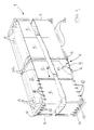
- Fig. 1 is a partly cut-away perspective view of the overall structure of the display device according to the invention, showing the rollers and traction means;
- Fig. 2 is a schematic top plan view of the display device according to the invention; and
- Fig. 3 is a partly sectional detail view, to an enlarged scale, illustrating an end of a roller and said traction means.
- More in detail, with reference to the above-cited drawing figures, the display device according to the invention, generally indicated by the
reference numeral 1 comprises a plurality ofpanels 2 and aframe 3, adapted for rotatably supporting a plurality ofrollers 4 which in the illustrated example have substantially vertical axes, saidframe 3 advantageously defining a substantially parallelepipedal form and has at least one open face wherethrough saidpanels 2 may be viewed. - Said
rollers 4 are adapted for the tensioning and entraining said plurality offlexible panels 2, which are expediently joined together in a closed-loop formation, which is movable relatively to the frame and attached to traction means 5 which are arranged movable inrelated guides 6, which in the exemplified embodiment are horizontal and are placed at the base and at the top of theframe 3. Adjustment means 7 are also provided for adjusting the tension of said closed-loop formation or belt ofpanels 2, as well asmeans 8 for illuminating the same, which will be described hereinafter. - Said traction means 5 are prefereably composed of two substantially parallel chains 9, each chain being advantageously arranged in a corresponding closed-loop formation and adapted to be driven by drive means such as a
motor 10. Expediently, interposed between each chain 9 and the inner surfaces of theguides 6 are anti-friction means 11, which may comprise, for instance, inserts or liners, advantageously made of self-lubricating material. The chains are also provided with a plurality of connection elements which, in the illustrated example comprise a plurality ofplates 12, which are advantageously substantially equidistantly spaced from each other and adapted for engagement relationship withresilient elements 13, interposed respectively between the lower chain and the base edge 2a of each panel and between the upper chain and thetop edge 2b of eachpanel 2. - The
means 7 for adjusting the tension of the closed-loop formation ofpanels 2 advantageously comprise at least one adjustment roller 4a, which, in a similar manner to therollers 4, is also freely rotatably mounted on theframe 3. The ends of the roller 4a are supported by respective heads, which are provided withdowels 14, which dowels are slideable and selectively lockable at a desired position alongholes 15, essentially extending parallel to each other and, in the case of employing substantially vertical rollers, as in the illustrated example, theholes 15 may be provided in the base and in the top of theframe 3, and define a substantially horizontal extension. - The operation of the device according to the invention, in the preferred illustrated embodiment thereof, is as follows: the
panels 2 may be joined to each other by any suitable link means, e.g. a bound seam 16, as schematically illustrated in Fig. 2, clips, edge binders or the like link elements, to form a closed-loop formation or belt, which belt is simultaneously wound around the plurality ofrollers 4, and he tensioning roller 4a, which, although in the illustrated embodiment are mounted vertically, may be alternatively mounted horizontally, when it is desired to provide vertically movable panels. As mentioned hereinabove, the rollers are freely rotatable, and supported by theframe 3. - The respective opposite upper edge 2a and
lower edge 2b of eachpanel 2 in the plurality of panels are engaged, byelastic elements 13, interposed between theedges 2a, 2b and theplates 12, which are rigidly coupled to the chains 9. - The arrangement of the plurality of
elements 13 ensures that thepanels 2 are always properly automatically maintained in a taut condition in the direction of the axes of therollers 4, whilst the arrangement ofrollers 4 including the adjustment roller 4a, permits this result to be perfected in a horizontal direction by intervening on theadjustment elements 7, i.e. by sliding thedowels 14 along therespective slots 15 and locking them at a desired position, to preset the required tension of the belt or closed-loop formation ofpanels 2, in the direction of the longitudinal extension of the chains. - Thus, by operating the
motor 10, the chains entrain, in the case illustrated, thepanels 2 in a horizontal direction, which can therefore alternate to the viewing of the public through one of the larger vertical faces of theframe 3. - Obviously, any suitable external panels may be applied to the
frame 3 as desired, to protect the mechanism from the elements, and to define any number of desired openings wherethrough thepanels 2 may be observed. Such openings may define any desired conformation according to the optical effects one wishes to achieve. Alternatively, one or more of such external covering elements or panels of transparent material, or thepanels 2 themselves may be made of weather resistant material, advantageously a translucent material. - For nighttime display, illuminating
means 8 may also be provided, which can be arranged either behind thesame panels 2, making them visible by making use of the partial transparency of the material which composes them, or by illuminating the visible part thereof in a direct manner. - If the substitution of one or more of
said panels 2 is required, it is sufficient to disengage it from both of the adjacent panels, which nevertheless maintain their correct position, by releasing the links 16, and disengaging the panel to be substituted from the chains 9 by removing theresilient elements 13. - The
new panel 2 is then positioned by reversing the procedure required to effect removal of the replaced panel. - In practice, it has been found that the invention thus described fully achieves the proposed aim and object.
- The invention thus conceived is susceptible of several modifications and variations, all of which fall within the scope of the inventive concept; thus, as an example, the duration of the exposure of each panel can be extended for a preset time by an electronic programmer or by a time-controlled electromechanical device.
- Furthermore, all the details can be replaced with other technically equivalent elements.
- In practice, any materials, shapes and dimensions may be employed according to contingent requirements.
Claims (6)
Priority Applications (1)
| Application Number | Priority Date | Filing Date | Title |
|---|---|---|---|
| AT86112048T ATE54033T1 (en) | 1985-09-06 | 1986-09-01 | INDICATOR. |
Applications Claiming Priority (2)
| Application Number | Priority Date | Filing Date | Title |
|---|---|---|---|
| IT4009185 | 1985-09-06 | ||
| IT8540091A IT1210154B (en) | 1985-09-06 | 1985-09-06 | VERTICAL DISPLAY OF A SERIES OF FLEXIBLE ADVERTISING PANELS |
Publications (2)
| Publication Number | Publication Date |
|---|---|
| EP0214587A1 true EP0214587A1 (en) | 1987-03-18 |
| EP0214587B1 EP0214587B1 (en) | 1990-06-20 |
Family
ID=11247953
Family Applications (1)
| Application Number | Title | Priority Date | Filing Date |
|---|---|---|---|
| EP86112048A Expired - Lifetime EP0214587B1 (en) | 1985-09-06 | 1986-09-01 | Display device |
Country Status (5)
| Country | Link |
|---|---|
| EP (1) | EP0214587B1 (en) |
| AT (1) | ATE54033T1 (en) |
| DE (1) | DE3672172D1 (en) |
| ES (1) | ES2001690A6 (en) |
| IT (1) | IT1210154B (en) |
Cited By (7)
| Publication number | Priority date | Publication date | Assignee | Title |
|---|---|---|---|---|
| US5018289A (en) * | 1988-05-10 | 1991-05-28 | Product Innovations | Changeable sign display device with improved panel suspension |
| US5138781A (en) * | 1991-01-16 | 1992-08-18 | Quadra View Incorporated | Multifaced variable display device |
| WO1994012968A1 (en) * | 1992-12-03 | 1994-06-09 | Italo Giacomini | Display panel for displaying messages written on a rotating loop consisting of webs interconnected by means of eyelets |
| US5657561A (en) * | 1995-10-26 | 1997-08-19 | Zykov; Valeri | Multi-year calendar device |
| WO2006103322A1 (en) * | 2005-03-30 | 2006-10-05 | Prismaflex International | Modular structure display device |
| WO2007020096A2 (en) * | 2005-08-17 | 2007-02-22 | Frank Winkelmann | Advertising surface structure |
| WO2008060252A1 (en) * | 2006-11-16 | 2008-05-22 | Seda Reklam Tanitim Hizmet Organizasyon Sanayi Ticaret Limited Sirketi | Advertisement panel tensioning system |
Families Citing this family (1)
| Publication number | Priority date | Publication date | Assignee | Title |
|---|---|---|---|---|
| DE10213711A1 (en) * | 2002-03-27 | 2003-10-16 | Gerriets Gmbh | Device for presenting alternating, large format advertising information items has lugs on carrier for laterally guiding medium, chains or element strips guided in rail with devices for engaging lugs |
Citations (6)
| Publication number | Priority date | Publication date | Assignee | Title |
|---|---|---|---|---|
| CH104218A (en) * | 1922-11-01 | 1924-04-16 | Dusseris Henri Francois Etienn | An advertisement driving device for mobile advertising devices. |
| FR637680A (en) * | 1927-07-04 | 1928-05-05 | Advertising device | |
| CH149582A (en) * | 1930-12-04 | 1931-09-15 | Mersing Josef | Apparatus for movable neon advertising. |
| DE643531C (en) * | 1935-07-14 | 1937-04-10 | Josef Lauter | Advertising device with traveling illuminated picture or writing tape |
| US3824721A (en) * | 1972-06-22 | 1974-07-23 | Pylon Inc | Outdoor display device for sequentially displaying a series of panels |
| US3972140A (en) * | 1975-01-15 | 1976-08-03 | Don Fedderson Productions Inc. | Portable dynamic advertising display system |
-
1985
- 1985-09-06 IT IT8540091A patent/IT1210154B/en active
-
1986
- 1986-09-01 AT AT86112048T patent/ATE54033T1/en not_active IP Right Cessation
- 1986-09-01 DE DE8686112048T patent/DE3672172D1/en not_active Expired - Fee Related
- 1986-09-01 EP EP86112048A patent/EP0214587B1/en not_active Expired - Lifetime
- 1986-09-05 ES ES8602001A patent/ES2001690A6/en not_active Expired
Patent Citations (6)
| Publication number | Priority date | Publication date | Assignee | Title |
|---|---|---|---|---|
| CH104218A (en) * | 1922-11-01 | 1924-04-16 | Dusseris Henri Francois Etienn | An advertisement driving device for mobile advertising devices. |
| FR637680A (en) * | 1927-07-04 | 1928-05-05 | Advertising device | |
| CH149582A (en) * | 1930-12-04 | 1931-09-15 | Mersing Josef | Apparatus for movable neon advertising. |
| DE643531C (en) * | 1935-07-14 | 1937-04-10 | Josef Lauter | Advertising device with traveling illuminated picture or writing tape |
| US3824721A (en) * | 1972-06-22 | 1974-07-23 | Pylon Inc | Outdoor display device for sequentially displaying a series of panels |
| US3972140A (en) * | 1975-01-15 | 1976-08-03 | Don Fedderson Productions Inc. | Portable dynamic advertising display system |
Cited By (9)
| Publication number | Priority date | Publication date | Assignee | Title |
|---|---|---|---|---|
| US5018289A (en) * | 1988-05-10 | 1991-05-28 | Product Innovations | Changeable sign display device with improved panel suspension |
| US5138781A (en) * | 1991-01-16 | 1992-08-18 | Quadra View Incorporated | Multifaced variable display device |
| WO1994012968A1 (en) * | 1992-12-03 | 1994-06-09 | Italo Giacomini | Display panel for displaying messages written on a rotating loop consisting of webs interconnected by means of eyelets |
| US5657561A (en) * | 1995-10-26 | 1997-08-19 | Zykov; Valeri | Multi-year calendar device |
| WO2006103322A1 (en) * | 2005-03-30 | 2006-10-05 | Prismaflex International | Modular structure display device |
| FR2884025A1 (en) * | 2005-03-30 | 2006-10-06 | Prismaflex Internat Sa | MODULAR STRUCTURE DISPLAY DEVICE |
| WO2007020096A2 (en) * | 2005-08-17 | 2007-02-22 | Frank Winkelmann | Advertising surface structure |
| WO2007020096A3 (en) * | 2005-08-17 | 2007-08-23 | Frank Winkelmann | Advertising surface structure |
| WO2008060252A1 (en) * | 2006-11-16 | 2008-05-22 | Seda Reklam Tanitim Hizmet Organizasyon Sanayi Ticaret Limited Sirketi | Advertisement panel tensioning system |
Also Published As
| Publication number | Publication date |
|---|---|
| ES2001690A6 (en) | 1988-06-01 |
| EP0214587B1 (en) | 1990-06-20 |
| IT1210154B (en) | 1989-09-06 |
| IT8540091A0 (en) | 1985-09-06 |
| ATE54033T1 (en) | 1990-07-15 |
| DE3672172D1 (en) | 1990-07-26 |
Similar Documents
| Publication | Publication Date | Title |
|---|---|---|
| US6105290A (en) | Display device | |
| US5138781A (en) | Multifaced variable display device | |
| US5018289A (en) | Changeable sign display device with improved panel suspension | |
| EP0214587A1 (en) | Display device | |
| US4680883A (en) | Scroll module and sign system for internally illuminated signs | |
| US7000343B1 (en) | Flexible platen image display device and method | |
| KR100309821B1 (en) | Device for displaying poster sets individually and selectively | |
| EP0746838B1 (en) | Display device | |
| US2935806A (en) | Outdoor poster advertising apparatus | |
| CN201146009Y (en) | Multi-menu exhibiting device | |
| US3299551A (en) | Display device | |
| US20070107282A1 (en) | Advertising device | |
| EP0687376A1 (en) | Film winding mechanism and display apparatus | |
| NO300946B1 (en) | Panel for displaying information, such as advertising texts | |
| EP0156142A1 (en) | Display panel for changeable advertisements or information, and display unit employing such a panel | |
| DE69214524T2 (en) | Modular frame arrangement for illuminated light displays with flexible material | |
| KR200293017Y1 (en) | The apparatus for advertisement | |
| GB2165075A (en) | Information display unit | |
| KR200293016Y1 (en) | The apparatus for advertisement | |
| US4434568A (en) | Graphic display assembly for dynamic program presentation | |
| AU692771B2 (en) | Display device | |
| US908854A (en) | Advertising apparatus. | |
| EP0290404A2 (en) | Advertising display board with interchangeable images | |
| WO1999005665A1 (en) | Poster display device | |
| JPH0527690A (en) | Multifaced bulletin board |
Legal Events
| Date | Code | Title | Description |
|---|---|---|---|
| PUAI | Public reference made under article 153(3) epc to a published international application that has entered the european phase |
Free format text: ORIGINAL CODE: 0009012 |
|
| AK | Designated contracting states |
Kind code of ref document: A1 Designated state(s): AT BE CH DE FR GB LI LU NL SE |
|
| 17P | Request for examination filed |
Effective date: 19870826 |
|
| 17Q | First examination report despatched |
Effective date: 19890222 |
|
| GRAA | (expected) grant |
Free format text: ORIGINAL CODE: 0009210 |
|
| AK | Designated contracting states |
Kind code of ref document: B1 Designated state(s): AT BE CH DE FR GB LI LU NL SE |
|
| PG25 | Lapsed in a contracting state [announced via postgrant information from national office to epo] |
Ref country code: SE Effective date: 19900620 Ref country code: NL Effective date: 19900620 Ref country code: BE Effective date: 19900620 Ref country code: AT Effective date: 19900620 |
|
| REF | Corresponds to: |
Ref document number: 54033 Country of ref document: AT Date of ref document: 19900715 Kind code of ref document: T |
|
| REF | Corresponds to: |
Ref document number: 3672172 Country of ref document: DE Date of ref document: 19900726 |
|
| ET | Fr: translation filed | ||
| PG25 | Lapsed in a contracting state [announced via postgrant information from national office to epo] |
Ref country code: LU Free format text: LAPSE BECAUSE OF NON-PAYMENT OF DUE FEES Effective date: 19900930 |
|
| NLV1 | Nl: lapsed or annulled due to failure to fulfill the requirements of art. 29p and 29m of the patents act | ||
| PLBE | No opposition filed within time limit |
Free format text: ORIGINAL CODE: 0009261 |
|
| STAA | Information on the status of an ep patent application or granted ep patent |
Free format text: STATUS: NO OPPOSITION FILED WITHIN TIME LIMIT |
|
| 26N | No opposition filed | ||
| PGFP | Annual fee paid to national office [announced via postgrant information from national office to epo] |
Ref country code: DE Payment date: 19910916 Year of fee payment: 6 |
|
| PGFP | Annual fee paid to national office [announced via postgrant information from national office to epo] |
Ref country code: CH Payment date: 19910926 Year of fee payment: 6 |
|
| PGFP | Annual fee paid to national office [announced via postgrant information from national office to epo] |
Ref country code: GB Payment date: 19910930 Year of fee payment: 6 |
|
| PG25 | Lapsed in a contracting state [announced via postgrant information from national office to epo] |
Ref country code: GB Effective date: 19920901 |
|
| PG25 | Lapsed in a contracting state [announced via postgrant information from national office to epo] |
Ref country code: LI Effective date: 19920930 Ref country code: CH Effective date: 19920930 |
|
| PGFP | Annual fee paid to national office [announced via postgrant information from national office to epo] |
Ref country code: FR Payment date: 19920930 Year of fee payment: 7 |
|
| GBPC | Gb: european patent ceased through non-payment of renewal fee |
Effective date: 19920901 |
|
| REG | Reference to a national code |
Ref country code: CH Ref legal event code: PL |
|
| PG25 | Lapsed in a contracting state [announced via postgrant information from national office to epo] |
Ref country code: DE Effective date: 19930602 |
|
| PG25 | Lapsed in a contracting state [announced via postgrant information from national office to epo] |
Ref country code: FR Free format text: LAPSE BECAUSE OF NON-PAYMENT OF DUE FEES Effective date: 19940531 |
|
| REG | Reference to a national code |
Ref country code: FR Ref legal event code: ST |