EP0214355B1 - A device for the conservation and the time-distribution of food for animals - Google Patents
A device for the conservation and the time-distribution of food for animals Download PDFInfo
- Publication number
- EP0214355B1 EP0214355B1 EP85830217A EP85830217A EP0214355B1 EP 0214355 B1 EP0214355 B1 EP 0214355B1 EP 85830217 A EP85830217 A EP 85830217A EP 85830217 A EP85830217 A EP 85830217A EP 0214355 B1 EP0214355 B1 EP 0214355B1
- Authority
- EP
- European Patent Office
- Prior art keywords
- container
- food
- bins
- support member
- above mentioned
- Prior art date
- Legal status (The legal status is an assumption and is not a legal conclusion. Google has not performed a legal analysis and makes no representation as to the accuracy of the status listed.)
- Expired
Links
Images


Classifications
-
- A—HUMAN NECESSITIES
- A01—AGRICULTURE; FORESTRY; ANIMAL HUSBANDRY; HUNTING; TRAPPING; FISHING
- A01K—ANIMAL HUSBANDRY; CARE OF BIRDS, FISHES, INSECTS; FISHING; REARING OR BREEDING ANIMALS, NOT OTHERWISE PROVIDED FOR; NEW BREEDS OF ANIMALS
- A01K5/00—Feeding devices for stock or game ; Feeding wagons; Feeding stacks
- A01K5/02—Automatic devices
- A01K5/0291—Automatic devices with timing mechanisms, e.g. pet feeders
Definitions
- the present invention concerns a device for the conservation, in a cold and/or frozen ambient, of food for animals, wherein said device will automatically distribute in several subsequent stages and/or in subsequent days, precooked or previously prepared foods for animals.
- US-A-2 528 742 discloses a device which has those features contained in the preamble of Claim 1.
- the present invention concerns a device for the conservation and the time-distribution of food for animals, comprising a compressor 1 placed above, or in any other disposition with respect to ambient 26 being cooled or frozen, a condenser 2 for the gases placed below said ambient 26 and/or in any other disposition, an evaporator, 3, a thermostat 4 for the continuous temperature regulation.
- the walls of the cooled ambient 26 are coated with an insulating material 5.
- Ambient 26 shows an opening in the upper cover corresponding to the opening in the bottom and through which the condenser 2 and the gap 24 of insulating edge 5 is visible so as to form two openings placed in the inner side parts being provided with compressable gaskets 6.
- the opening has a shape and a dimension equal to the one of a bin of container 7 or fodder trough, and the openings are slightly wider than the length of a radius of the same container, and just a little higher.
- the above mentioned fodder trough/container 7 shows the edges of the insulated walls 9 of the supporting structure duly rounded 42, it is open on the upper part 35 and consists in a plurality of bins, which can be extracted, separated by insulated walls 9 which form the supporting structure, preferably of a plastic material, kept in one single body with the supporting structure, by means of fixed joints ties 43.
- the perfect thermal sealing of the above mentioned ambient 26 is provided thanks to the gaskets 6, and to the relevant support 30 ; the above mentioned gaskets, once they have got into contact with the perimeter of the rounded walls of the support with insulated walls 9 of the fodder trough/container 7 and which are separating the bins/cups, form a completely insulated barrier thus keeping the low temperature of the ambient 26 insulated and closed, and leaving outside of the cooling but within the device a bin 22 of the fodder trough/container 7, which, since it has its upper part open, places the food contained therein at the animal's disposal.
- the programmed timer calculates the acclimatization times according to the local temperature. or anyway air temperature, and disconnects the electromagnet E, by returning the small plunger calling back said electromagnet E, with mobile cover CM incorporated and hinged at the centre of the device, to the starting place by means of a previously tensioned spring or elastic band.
- the same even if remaining below the device's structure, will be placed and will have a structure such as to have the maximum possible ventilation, as well as in such a position as to favour the maximum heating, making a flow in warm air, of the bin that has come out of the cooled or frozen area containing the food, for instance by distancing the same from the edge of the device and by inclining the same in such a way, that the higher part thereof may get under the bin with the food for the animal, thus favouring the sliding of the warm air towards the top and into said area.
- the coil condenser 2 even if partially remaining under the above mentioned device (in the area under the bin that has come out from the cooled or frozen area) will be, in part, vertically placed nearby the rounded side of the device with an approriate protection, thus improving the ventilation thereof.
- Coil 2 is provided with a container 53 in order to recollect the water coming from ambient 26.
- a further feature of the present invention consists in that the fodder trough/container 7 with rounded edges 42 has the openings 35 thereof in its upper part and is formed by a central structure with insulated walls 9 and several bins forming one single body by means of the joints 36 as well as fixed joints ties (male points on the fixed joints ties 43 to be inserted into the female holes of the mobile bins).
- the bins are extractable, since they are just placed under pressure and joints by means of the ties with male tips 43 placed on the sides of the central body of the fodder trough/container 7, and the holes existing on the corresponding sides of the bins 22 ; as well as for the joint 36 to be placed under the round part of the central body.
- the cooled ambient 26 has a small discharge pipe 37 for the water coming from the cooling and/or freezing plate 3 and that will get into the recollecting container 53 placed under the above mentioned ambient 26, said container being incorporated in the cooling grate of coil 2.
- the present invention shows moreover a wheel 60 placed within the ambient 26, on the side opposite to the open one where the animal takes the food, above and in contact with the insulated wall 9 that will be placed below the fodder trough/container 7 when the same is stopped in the feedbox position ; said wheel will serve so that when a bin of the container will be inserted into the open area, the pressure performed onto the central body of the above mentioned fodder trough/container 7 will be counteracted by the wheel's 60 resistance which, in turn, by means of its supports, rests and is supported on the ceiling of the ambient 26 ; therefore nothing is moving when the pressure is exerted.
- the wheel 12 is installed within the ambient 26 on the side opposite to the open one where the animal takes the food, under the insulated wall 9 and in contact with the same, that will be placed above when the fodder trough/container 7 is stopped in its feedbox position ; the above mentioned whell will serve in order to obtain that when a bin of the fodder trough/container 7 is extracted, the pressure performed on the central body of same will be counteracted by the resistance of the wheel 12 which in turn, and by means of its supports, rests and is supported, being fixed on the floor of the ambient 26, so that nothing is moved, when the pressure is exerted.
- the buffer circuit C loads the accumulators as well as the commutation circuit, for the 12V feeding of the timers T, and T 2 as well as of the relays R, and R 2 .
- the timer T has a twentyfour -hours plus one minute cycle, in other words it provides the relay R, with voltage, the relay R, being powered gives a starter pulse to the timer T 2 thus powering the relay R 2 for a time period variable between one and three hours or more, by means of a command to be given to the timer T, or"T 2 .
- the relay R 2 gives voltage to the electromagnet E, and the said electromagnet hooks, during its passage, the fodder trough/container 7 in its predetermined slot thus providing a covering for the time previously determined by the timer T 2 .
- the relay R feeds the small motor 29 thus causing the fodder trough/container 7 to turn.
- the microswitch MS being operated by a depression on the fodder trough/container 7, will provide a stop pulse to the timer T, or T 2 that releases the relay R 2 thus disconnecting the voltage from the small motor 29.
Description
- The present invention concerns a device for the conservation, in a cold and/or frozen ambient, of food for animals, wherein said device will automatically distribute in several subsequent stages and/or in subsequent days, precooked or previously prepared foods for animals.
- The need of feeding small home animals during one's absence from home on week-ends or on other occasions, when particularly cats and dogs must be left alone even for more days, is well known.
- US-A-2 528 742 discloses a device which has those features contained in the preamble of Claim 1.
- It is the aim of the present invention to realize an easy to operate, and not expensive device for the conservation and/or automatic time-distribution of previously prepared food.
- The aim is reached by means of the device according to Claim 1.
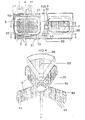
- The present invention will be shown hereinbelow in a preferred embodiment in figures 1 to 7 of the attached drawings, which show:
- figure 1, an axonometric view of the whole device ;
- figure 2, a top view ;
- figure 3, a vertical section ;
- figure 4, a perspective view of the structure with a plurality of bins ;
- figures 5 and 6, sections B-C and D-E of the figure 3 ;
- figure 7, the scheme of the electric plant.
- The present invention concerns a device for the conservation and the time-distribution of food for animals, comprising a compressor 1 placed above, or in any other disposition with respect to ambient 26 being cooled or frozen, a
condenser 2 for the gases placed below said ambient 26 and/or in any other disposition, an evaporator, 3, athermostat 4 for the continuous temperature regulation. - The walls of the cooled ambient 26 are coated with an
insulating material 5. - Ambient 26 shows an opening in the upper cover corresponding to the opening in the bottom and through which the
condenser 2 and thegap 24 ofinsulating edge 5 is visible so as to form two openings placed in the inner side parts being provided withcompressable gaskets 6. - The opening has a shape and a dimension equal to the one of a bin of
container 7 or fodder trough, and the openings are slightly wider than the length of a radius of the same container, and just a little higher. - The above mentioned fodder trough/
container 7 shows the edges of the insulated walls 9 of the supporting structure duly rounded 42, it is open on theupper part 35 and consists in a plurality of bins, which can be extracted, separated by insulated walls 9 which form the supporting structure, preferably of a plastic material, kept in one single body with the supporting structure, by means offixed joints ties 43. - The above mentioned fodder trough/
container 7, once it is placed into the cooled ambient 26 resting, on its bottom, on a plurality ofwheels 12 and laterally on thewheels electric motor 29 withhelical end 33, thus causing themating gears circular toothing 48, thus causing the rotation that will be stopped by the above mentioned timer 18 when the ball axis releases the impulse by entering in the provided housing, in such a way that the cup with the predetermined food shall be placed intoposition 22, outside of the ambient 26. - The perfect thermal sealing of the above mentioned ambient 26 is provided thanks to the
gaskets 6, and to therelevant support 30 ; the above mentioned gaskets, once they have got into contact with the perimeter of the rounded walls of the support with insulated walls 9 of the fodder trough/container 7 and which are separating the bins/cups, form a completely insulated barrier thus keeping the low temperature of the ambient 26 insulated and closed, and leaving outside of the cooling but within the device abin 22 of the fodder trough/container 7, which, since it has its upper part open, places the food contained therein at the animal's disposal. - In order to prevent that a too cold food may be immediately eaten by the animal, the device is provided (in the zone above the food to be eaten 22) with a programmable mobile cover CM, automatically opening in due time, thus putting the food at the animal's disposal when the temperature is suitable for swallowing, and this with the following procedure :
- when the fodder trough/
container 7 is moving in order to release another meal, the electromagnet E, being incorporated in the cover CM, is coupled with one of the appropriate slots of the fodder trough/container 7 thus carrying the above mentioned cover with a slow motion, over the new meal ; - the circulation of hot air in summer, or the circulation of the air coming up at a higher temperature when the coil condenser underneath is in operation, and, optionally, also a resistance, passes in direct contact with the food (open zone of the bin 22), with the bottom and all the walls of the same bin 22 (more precisely, it passes through the interspaces between the cup and the insulated walls 9) bringing the food to the temperature which is suitable for eating.
- The programmed timer calculates the acclimatization times according to the local temperature. or anyway air temperature, and disconnects the electromagnet E, by returning the small plunger calling back said electromagnet E, with mobile cover CM incorporated and hinged at the centre of the device, to the starting place by means of a previously tensioned spring or elastic band.
- In a construction variant concerning the displacement of the
coil condenser 2, the same, even if remaining below the device's structure, will be placed and will have a structure such as to have the maximum possible ventilation, as well as in such a position as to favour the maximum heating, making a flow in warm air, of the bin that has come out of the cooled or frozen area containing the food, for instance by distancing the same from the edge of the device and by inclining the same in such a way, that the higher part thereof may get under the bin with the food for the animal, thus favouring the sliding of the warm air towards the top and into said area. - In a further variant, the
coil condenser 2, even if partially remaining under the above mentioned device (in the area under the bin that has come out from the cooled or frozen area) will be, in part, vertically placed nearby the rounded side of the device with an approriate protection, thus improving the ventilation thereof. - Furthermore, so as to cause the evaporator with the
cooling plate 3 to better lead the cold to thefood 7, even remaining under the container with a plurality of bins, it will be preferable to extend the same also sideways, and/or above the said container. - Should the warmth from the condenser for . warming up the animal's food not be enough (if the device is placed outside and with a particularly cold weather), and should it be required, a further warming system will be provided, for instance, by means of an electric resistance or other means.
-
Coil 2 is provided with acontainer 53 in order to recollect the water coming from ambient 26. - A further feature of the present invention consists in that the fodder trough/
container 7 withrounded edges 42 has theopenings 35 thereof in its upper part and is formed by a central structure with insulated walls 9 and several bins forming one single body by means of thejoints 36 as well as fixed joints ties (male points on thefixed joints ties 43 to be inserted into the female holes of the mobile bins). The bins are extractable, since they are just placed under pressure and joints by means of the ties withmale tips 43 placed on the sides of the central body of the fodder trough/container 7, and the holes existing on the corresponding sides of thebins 22 ; as well as for thejoint 36 to be placed under the round part of the central body. - The cooled ambient 26 has a
small discharge pipe 37 for the water coming from the cooling and/or freezingplate 3 and that will get into the recollectingcontainer 53 placed under the above mentioned ambient 26, said container being incorporated in the cooling grate ofcoil 2. - The present invention shows moreover a
wheel 60 placed within the ambient 26, on the side opposite to the open one where the animal takes the food, above and in contact with the insulated wall 9 that will be placed below the fodder trough/container 7 when the same is stopped in the feedbox position ; said wheel will serve so that when a bin of the container will be inserted into the open area, the pressure performed onto the central body of the above mentioned fodder trough/container 7 will be counteracted by the wheel's 60 resistance which, in turn, by means of its supports, rests and is supported on the ceiling of the ambient 26 ; therefore nothing is moving when the pressure is exerted. - Finally, the
wheel 12 is installed within the ambient 26 on the side opposite to the open one where the animal takes the food, under the insulated wall 9 and in contact with the same, that will be placed above when the fodder trough/container 7 is stopped in its feedbox position ; the above mentioned whell will serve in order to obtain that when a bin of the fodder trough/container 7 is extracted, the pressure performed on the central body of same will be counteracted by the resistance of thewheel 12 which in turn, and by means of its supports, rests and is supported, being fixed on the floor of the ambient 26, so that nothing is moved, when the pressure is exerted. - For what concerns the operation of the electric plant according to the figure 7, the buffer circuit C loads the accumulators as well as the commutation circuit, for the 12V feeding of the timers T, and T2 as well as of the relays R, and R2.
- The timer T, has a twentyfour -hours plus one minute cycle, in other words it provides the relay R, with voltage, the relay R, being powered gives a starter pulse to the timer T2 thus powering the relay R2 for a time period variable between one and three hours or more, by means of a command to be given to the timer T, or"T2.
- The relay R2 gives voltage to the electromagnet E, and the said electromagnet hooks, during its passage, the fodder trough/
container 7 in its predetermined slot thus providing a covering for the time previously determined by the timer T2. - At the same time, the relay R, feeds the
small motor 29 thus causing the fodder trough/container 7 to turn. - Once the partial rotation has been performed, the microswitch MS being operated by a depression on the fodder trough/
container 7, will provide a stop pulse to the timer T, or T2 that releases the relay R2 thus disconnecting the voltage from thesmall motor 29.
Claims (10)
Priority Applications (2)
| Application Number | Priority Date | Filing Date | Title |
|---|---|---|---|
| AT85830217T ATE37975T1 (en) | 1985-08-13 | 1985-08-13 | DEVICE FOR STORING AND DISPENSING ANIMAL FOOD AT SPECIFIC TIMES. |
| DE8585830217T DE3565623D1 (en) | 1985-08-13 | 1985-08-13 | A device for the conservation and the time-distribution of food for animals |
Applications Claiming Priority (1)
| Application Number | Priority Date | Filing Date | Title |
|---|---|---|---|
| IT47770/84A IT1178357B (en) | 1984-02-28 | 1984-02-28 | PRESERVING MACHINE - DISTRIBUTOR, AT ADJUSTABLE TIMES, OF FOOD mainly intended for ANIMALS |
Publications (2)
| Publication Number | Publication Date |
|---|---|
| EP0214355A1 EP0214355A1 (en) | 1987-03-18 |
| EP0214355B1 true EP0214355B1 (en) | 1988-10-19 |
Family
ID=11262409
Family Applications (1)
| Application Number | Title | Priority Date | Filing Date |
|---|---|---|---|
| EP85830217A Expired EP0214355B1 (en) | 1984-02-28 | 1985-08-13 | A device for the conservation and the time-distribution of food for animals |
Country Status (3)
| Country | Link |
|---|---|
| US (1) | US4617874A (en) |
| EP (1) | EP0214355B1 (en) |
| IT (1) | IT1178357B (en) |
Families Citing this family (37)
| Publication number | Priority date | Publication date | Assignee | Title |
|---|---|---|---|---|
| DK163328C (en) * | 1987-10-28 | 1992-07-13 | Mogens Arentoft | PROCEDURE AND FEEDING PLANT FOR FEEDING ANIMALS, NAME MINK, USING SUGAR FEED |
| GB2214329A (en) * | 1987-12-24 | 1989-08-31 | Lee Tien Yung | Automatic animal feeder |
| US4932361A (en) * | 1988-06-20 | 1990-06-12 | Harold L. Deutsch | Animal feeding system |
| US5129361A (en) * | 1988-06-20 | 1992-07-14 | Harold L. Deutsch | Animal feeding system |
| FR2664129A1 (en) * | 1990-07-09 | 1992-01-10 | Thuillier Patrick | Automatic food dispenser for animals, in particular for a dog |
| GB9018674D0 (en) * | 1990-08-24 | 1990-10-10 | Pet Mate Ltd | Dispensing device |
| US5377620A (en) * | 1993-09-13 | 1995-01-03 | Phillippi; Daniel J. | Carousel animal feeder |
| US5669328A (en) * | 1996-06-14 | 1997-09-23 | Lanfranchi; Tammy | Automatic animal feeding system |
| US5950567A (en) * | 1996-11-01 | 1999-09-14 | Lab Products, Inc. | Multiple dosage feeder for animal cage |
| US5975024A (en) * | 1997-10-31 | 1999-11-02 | Lab Products, Inc. | Cage for receiving a feeder |
| NL1014896C2 (en) * | 2000-04-10 | 2001-10-30 | Lely Entpr Ag | Feed dosing device. |
| US6349671B1 (en) * | 2000-06-29 | 2002-02-26 | Nan R. W. Lewis | Pet feeding system and method of using same |
| US6766766B1 (en) * | 2001-03-29 | 2004-07-27 | Lawrence T. Elliott | Pet care center with refrigerated automatic feeder |
| US6694916B1 (en) * | 2001-09-01 | 2004-02-24 | Dogopolis, Llc | Timed food-filled toy dispenser |
| US7219620B2 (en) * | 2001-09-01 | 2007-05-22 | Dogopolis, Llc | Timed food-filled toy dispenser |
| US6550421B1 (en) | 2002-03-18 | 2003-04-22 | Besler Industries, Inc. | Automatic hay feeder |
| US7469657B2 (en) * | 2003-02-25 | 2008-12-30 | Alec Drummond | Apparatus and methods for controlling an animal's access to food |
| US7051675B1 (en) * | 2004-06-04 | 2006-05-30 | Mayer Richard E | Automatic animal feeder |
| US7267078B2 (en) * | 2005-03-17 | 2007-09-11 | Anthony Palett | Combination major appliance and pet watering system |
| US7650855B2 (en) * | 2007-05-24 | 2010-01-26 | Sundararajan Krishnamurthy | Automatic pet feeder |
| US7798100B2 (en) * | 2008-01-25 | 2010-09-21 | Dennis Bryant | Animal hay and grain feeder |
| US20090241848A1 (en) * | 2008-03-28 | 2009-10-01 | Dennis Bryant | Animal Waterer |
| US8061300B2 (en) * | 2008-09-18 | 2011-11-22 | Mcelroy Jr Perry D | Animal behavioral positive reinforcement apparatus and method of using same |
| US8499493B2 (en) * | 2011-04-25 | 2013-08-06 | Yan-Hua Biotech Co., Ltd. | Sprout cultivation device |
| USD676203S1 (en) * | 2011-06-17 | 2013-02-12 | Kyle Hansen | Jigsaw puzzle pet treat dispensing game |
| USD676619S1 (en) * | 2012-03-23 | 2013-02-19 | Kyle Hansen | Pet puzzle toy |
| USD681886S1 (en) * | 2012-04-19 | 2013-05-07 | Otis Industries, LLC | Aggressive eater dog bowl |
| US8800488B2 (en) * | 2012-10-02 | 2014-08-12 | Alex Jon Stone | Internet controlled pet feeder |
| US20150342144A1 (en) * | 2014-05-29 | 2015-12-03 | Jacob Matthew Palmatier | Animal food and products dispenser |
| CN104054592A (en) * | 2014-07-14 | 2014-09-24 | 南京通孚轻纺有限公司 | Automatic pet feeder |
| USD773127S1 (en) * | 2015-04-10 | 2016-11-29 | Pet Mate Limited | Cat feeder |
| US9675049B2 (en) * | 2015-04-10 | 2017-06-13 | Pawbo Inc. | Pet amusement device |
| GB2541012B (en) | 2015-08-06 | 2021-07-14 | Pet Mate Ltd | Position control of pet bowl |
| TWM550984U (en) * | 2017-01-06 | 2017-11-01 | Zong-Xin Chen | Pet feeding device |
| USD845555S1 (en) * | 2017-06-05 | 2019-04-09 | Guangdong Cuter Pet Technology Co., Ltd. | Automatic pet feeder |
| USD889049S1 (en) * | 2019-01-24 | 2020-06-30 | Dogness Group LLC | Pet bowl |
| USD1012379S1 (en) * | 2023-10-20 | 2024-01-23 | Shenzhen Jinzhouda Science & Technology Co., Ltd. | Automatic cat feeder |
Family Cites Families (6)
| Publication number | Priority date | Publication date | Assignee | Title |
|---|---|---|---|---|
| US2528742A (en) * | 1949-06-17 | 1950-11-07 | James R Coffing | Pet feeder |
| GB1546638A (en) * | 1977-09-02 | 1979-05-31 | Brill Edwards K O P | Food dispensing means for deomestic pets |
| IT1106168B (en) * | 1978-10-03 | 1985-11-11 | Pelosso Umberto | APPARATUS FOR THE REFRIGERATED STORAGE OF PET FOODS AND THE SUBSEQUENT SCHEDULED AND TIMED DISTRIBUTION PRIOR TO THE APPROPRIATE PREHEATING |
| US4248175A (en) * | 1979-11-14 | 1981-02-03 | Jesus Navarro | Automatic dog or cat feeder |
| US4450790A (en) * | 1982-09-30 | 1984-05-29 | Adon Sanchez | Animal feeding apparatus |
| DE3328762A1 (en) * | 1983-08-05 | 1985-02-14 | Erik Dipl.-Ing. 1000 Berlin Notthoff | Automatic feeding device for pets and small animals |
-
1984
- 1984-02-28 IT IT47770/84A patent/IT1178357B/en active
-
1985
- 1985-02-27 US US06/706,217 patent/US4617874A/en not_active Expired - Lifetime
- 1985-08-13 EP EP85830217A patent/EP0214355B1/en not_active Expired
Also Published As
| Publication number | Publication date |
|---|---|
| EP0214355A1 (en) | 1987-03-18 |
| US4617874A (en) | 1986-10-21 |
| IT8447770A0 (en) | 1984-02-28 |
| IT1178357B (en) | 1987-09-09 |
Similar Documents
| Publication | Publication Date | Title |
|---|---|---|
| EP0214355B1 (en) | A device for the conservation and the time-distribution of food for animals | |
| JP4593932B2 (en) | Refrigerator with ice maker | |
| EP3400411B1 (en) | Ice maker with rotating ice tray | |
| US4487024A (en) | Thermoelectric ice cube maker | |
| CN101730826B (en) | Refrigerator defrosting and chilling compartment | |
| US2846854A (en) | Ice cube maker | |
| US6038865A (en) | Temperature-controlled appliance | |
| US8146535B1 (en) | Thermally controlled drinking water system for animals | |
| US6363886B1 (en) | Heated/cooled live-food bird feeder | |
| US3791166A (en) | Clear ice pellet maker | |
| US4332142A (en) | Household refrigerator including anti-sweat heater control circuit | |
| US4385075A (en) | Method for thawing frozen food | |
| US4326390A (en) | Apparatus and method for thawing frozen food | |
| US2774224A (en) | Ice cube making refrigerator | |
| US6009835A (en) | Apparatus and method for dispensing frozen aquarium food | |
| US4590852A (en) | Cooling system for apparatus for processing frozen comestibles | |
| CA2329628A1 (en) | Refrigerating drawer for storage column | |
| ES2399720T3 (en) | Rotisserie spit | |
| US3106072A (en) | Refrigerator-freezer | |
| EP2457474A1 (en) | Electric refrigerator with rotating shelves | |
| JP3116050B2 (en) | Insulated box | |
| JPH07500484A (en) | Methods and devices for storing foodstuffs, plants, meat and other organic substances | |
| CN217826306U (en) | Pet meal feeder capable of freezing, preserving, thawing and heating | |
| CN211424814U (en) | Yoghourt frying refrigerator | |
| JPH0442711Y2 (en) |
Legal Events
| Date | Code | Title | Description |
|---|---|---|---|
| PUAI | Public reference made under article 153(3) epc to a published international application that has entered the european phase |
Free format text: ORIGINAL CODE: 0009012 |
|
| AK | Designated contracting states |
Kind code of ref document: A1 Designated state(s): AT BE CH DE FR GB LI NL SE |
|
| 17P | Request for examination filed |
Effective date: 19861112 |
|
| 17Q | First examination report despatched |
Effective date: 19870703 |
|
| GRAA | (expected) grant |
Free format text: ORIGINAL CODE: 0009210 |
|
| AK | Designated contracting states |
Kind code of ref document: B1 Designated state(s): AT BE CH DE FR GB LI NL SE |
|
| REF | Corresponds to: |
Ref document number: 37975 Country of ref document: AT Date of ref document: 19881115 Kind code of ref document: T |
|
| REF | Corresponds to: |
Ref document number: 3565623 Country of ref document: DE Date of ref document: 19881124 |
|
| ET | Fr: translation filed | ||
| PLBE | No opposition filed within time limit |
Free format text: ORIGINAL CODE: 0009261 |
|
| STAA | Information on the status of an ep patent application or granted ep patent |
Free format text: STATUS: NO OPPOSITION FILED WITHIN TIME LIMIT |
|
| 26N | No opposition filed | ||
| PGFP | Annual fee paid to national office [announced via postgrant information from national office to epo] |
Ref country code: BE Payment date: 19900913 Year of fee payment: 6 |
|
| PG25 | Lapsed in a contracting state [announced via postgrant information from national office to epo] |
Ref country code: BE Effective date: 19910831 |
|
| BERE | Be: lapsed |
Owner name: ZAMMARANO ALESSANDRO Effective date: 19910831 |
|
| EAL | Se: european patent in force in sweden |
Ref document number: 85830217.7 |
|
| REG | Reference to a national code |
Ref country code: CH Ref legal event code: PL |
|
| REG | Reference to a national code |
Ref country code: CH Ref legal event code: AEN Free format text: REINTEGRATION EN L'ETAT ANTERIEUR ACCORDEE |
|
| PGFP | Annual fee paid to national office [announced via postgrant information from national office to epo] |
Ref country code: AT Payment date: 19970826 Year of fee payment: 13 |
|
| REG | Reference to a national code |
Ref country code: FR Ref legal event code: ST |
|
| PG25 | Lapsed in a contracting state [announced via postgrant information from national office to epo] |
Ref country code: AT Free format text: LAPSE BECAUSE OF NON-PAYMENT OF DUE FEES Effective date: 19980813 |
|
| REG | Reference to a national code |
Ref country code: FR Ref legal event code: RN |
|
| REG | Reference to a national code |
Ref country code: FR Ref legal event code: FC |
|
| REG | Reference to a national code |
Ref country code: GB Ref legal event code: IF02 |
|
| PGFP | Annual fee paid to national office [announced via postgrant information from national office to epo] |
Ref country code: GB Payment date: 20030813 Year of fee payment: 19 |
|
| PGFP | Annual fee paid to national office [announced via postgrant information from national office to epo] |
Ref country code: NL Payment date: 20030826 Year of fee payment: 19 |
|
| PGFP | Annual fee paid to national office [announced via postgrant information from national office to epo] |
Ref country code: SE Payment date: 20030827 Year of fee payment: 19 Ref country code: FR Payment date: 20030827 Year of fee payment: 19 |
|
| PGFP | Annual fee paid to national office [announced via postgrant information from national office to epo] |
Ref country code: DE Payment date: 20040220 Year of fee payment: 19 Ref country code: CH Payment date: 20040220 Year of fee payment: 19 |
|
| PG25 | Lapsed in a contracting state [announced via postgrant information from national office to epo] |
Ref country code: GB Free format text: LAPSE BECAUSE OF NON-PAYMENT OF DUE FEES Effective date: 20040813 |
|
| PG25 | Lapsed in a contracting state [announced via postgrant information from national office to epo] |
Ref country code: SE Free format text: LAPSE BECAUSE OF NON-PAYMENT OF DUE FEES Effective date: 20040814 |
|
| PG25 | Lapsed in a contracting state [announced via postgrant information from national office to epo] |
Ref country code: LI Free format text: LAPSE BECAUSE OF NON-PAYMENT OF DUE FEES Effective date: 20040831 Ref country code: CH Free format text: LAPSE BECAUSE OF NON-PAYMENT OF DUE FEES Effective date: 20040831 |
|
| PG25 | Lapsed in a contracting state [announced via postgrant information from national office to epo] |
Ref country code: NL Free format text: LAPSE BECAUSE OF NON-PAYMENT OF DUE FEES Effective date: 20050301 Ref country code: DE Free format text: LAPSE BECAUSE OF NON-PAYMENT OF DUE FEES Effective date: 20050301 |
|
| EUG | Se: european patent has lapsed | ||
| GBPC | Gb: european patent ceased through non-payment of renewal fee |
Effective date: 20040813 |
|
| REG | Reference to a national code |
Ref country code: CH Ref legal event code: PL |
|
| PG25 | Lapsed in a contracting state [announced via postgrant information from national office to epo] |
Ref country code: FR Free format text: LAPSE BECAUSE OF NON-PAYMENT OF DUE FEES Effective date: 20050429 |
|
| NLV4 | Nl: lapsed or anulled due to non-payment of the annual fee |
Effective date: 20050301 |
|
| REG | Reference to a national code |
Ref country code: FR Ref legal event code: ST |