EP0213969A2 - Process and apparatus for biaxially stretching plastics materials, and products thereby obtained - Google Patents
Process and apparatus for biaxially stretching plastics materials, and products thereby obtained Download PDFInfo
- Publication number
- EP0213969A2 EP0213969A2 EP86400938A EP86400938A EP0213969A2 EP 0213969 A2 EP0213969 A2 EP 0213969A2 EP 86400938 A EP86400938 A EP 86400938A EP 86400938 A EP86400938 A EP 86400938A EP 0213969 A2 EP0213969 A2 EP 0213969A2
- Authority
- EP
- European Patent Office
- Prior art keywords
- film
- stretching
- generators
- load
- stretched
- Prior art date
- Legal status (The legal status is an assumption and is not a legal conclusion. Google has not performed a legal analysis and makes no representation as to the accuracy of the status listed.)
- Granted
Links
Images


Classifications
-
- B—PERFORMING OPERATIONS; TRANSPORTING
- B29—WORKING OF PLASTICS; WORKING OF SUBSTANCES IN A PLASTIC STATE IN GENERAL
- B29C—SHAPING OR JOINING OF PLASTICS; SHAPING OF MATERIAL IN A PLASTIC STATE, NOT OTHERWISE PROVIDED FOR; AFTER-TREATMENT OF THE SHAPED PRODUCTS, e.g. REPAIRING
- B29C55/00—Shaping by stretching, e.g. drawing through a die; Apparatus therefor
- B29C55/02—Shaping by stretching, e.g. drawing through a die; Apparatus therefor of plates or sheets
- B29C55/10—Shaping by stretching, e.g. drawing through a die; Apparatus therefor of plates or sheets multiaxial
- B29C55/12—Shaping by stretching, e.g. drawing through a die; Apparatus therefor of plates or sheets multiaxial biaxial
- B29C55/16—Shaping by stretching, e.g. drawing through a die; Apparatus therefor of plates or sheets multiaxial biaxial simultaneously
-
- B—PERFORMING OPERATIONS; TRANSPORTING
- B29—WORKING OF PLASTICS; WORKING OF SUBSTANCES IN A PLASTIC STATE IN GENERAL
- B29C—SHAPING OR JOINING OF PLASTICS; SHAPING OF MATERIAL IN A PLASTIC STATE, NOT OTHERWISE PROVIDED FOR; AFTER-TREATMENT OF THE SHAPED PRODUCTS, e.g. REPAIRING
- B29C55/00—Shaping by stretching, e.g. drawing through a die; Apparatus therefor
- B29C55/02—Shaping by stretching, e.g. drawing through a die; Apparatus therefor of plates or sheets
- B29C55/04—Shaping by stretching, e.g. drawing through a die; Apparatus therefor of plates or sheets uniaxial, e.g. oblique
- B29C55/045—Shaping by stretching, e.g. drawing through a die; Apparatus therefor of plates or sheets uniaxial, e.g. oblique in a direction which is not parallel or transverse to the direction of feed, e.g. oblique
-
- B—PERFORMING OPERATIONS; TRANSPORTING
- B65—CONVEYING; PACKING; STORING; HANDLING THIN OR FILAMENTARY MATERIAL
- B65B—MACHINES, APPARATUS OR DEVICES FOR, OR METHODS OF, PACKAGING ARTICLES OR MATERIALS; UNPACKING
- B65B11/00—Wrapping, e.g. partially or wholly enclosing, articles or quantities of material, in strips, sheets or blanks, of flexible material
- B65B11/04—Wrapping, e.g. partially or wholly enclosing, articles or quantities of material, in strips, sheets or blanks, of flexible material the articles being rotated
- B65B11/045—Wrapping, e.g. partially or wholly enclosing, articles or quantities of material, in strips, sheets or blanks, of flexible material the articles being rotated by rotating platforms supporting the articles
Definitions
- the present invention relates to automatic methods and apparatuses for carrying out the bi-axial drawing of plastic material and more particularly to automatic packaging methods.
- Plastics are commonly used to make protective packaging. For example, loads to be stored, transported or distributed may require protection for their handling or, against the environment, etc. Also, loads with multiple units may require packaging to carry out a single, monoblock load. easily manageable.
- Heat-shrinkable packaging consists of wrapping a load and then subjecting the packaging to a high temperature. This causes the plastic to contract, thereby tightening the load.
- the drawbacks of these heat-shrinkable packages are well known. In particular, they involve the use of heating means which are costly in investment and especially in operation.
- the packaging film can become rigid and thus cease to exert the desired compressive force.
- the second type of plastic packaging is stretch packaging.
- the load is wrapped in a stretched plastic film so that by contraction it encloses the load.
- the stretched plastic is not rigid and continues to maintain its compressive force even if the load remains at rest.
- the currently known stretch wrappers are not without limits.
- the stretchable packaging in which the contraction occurs in the length and in the width of the packaging film, that is to say bi-axially, the stretchable packaging is only contracted in the direction in which it was previously stretched. Since stretching in several directions simultaneously involves considerable mechanical problems, the stretchable plastic material has so far been stretched only lengthwise of the packaging film.
- wrapping machines and machines Two types of stretch film packaging machines on the market are currently known, available on the market. Wrapping machines and machines called “curtain” or “pass through”. In wrapping machines, the load is pivotally mounted or the film supply pivots around the load. In curtain machines the load is moved into a plastic film curtain shaped like a U and then welded behind the load.
- the plastic material considered may be continuous film or else a net or a material comprising meshes or the like. For the simplicity of the description, these different variants are referred to below as the film.
- Stretch packaging machines use different techniques to perform stretching.
- the first known technique is that of braking.
- wrapping machines this technique consists in braking the reel of packaging film when the load is rotated and, therefore, drives the film from the reel in question.
- curtain type machines the wrapping film curtain is generally made between two rolls of film. Braking is applied to one or both of the film reels when the load cooperates with the curtain for packaging. Welding devices close the film behind the load to achieve complete packaging.
- Braking devices stretch the wrapping film when wrapped around the load. This stretching produces a reduction in the width of the film usually called "NECK-DOWN", that is to say the structure of the film.
- This braking stretching technique has a number of drawbacks. The stretching is irregular due to the corners, angles, or projections of the load, which tends to cut the packaging film. To avoid film breakage, the stretch rate is generally decreased and this results in loose packaging. Finally, given that stretching is mainly carried out over the length of the packaging film, the packaging does not exert on the load a compressive force in the transverse direction of the film.
- pre-stretching In order to overcome some of these problems, a second stretching technique has been proposed called pre-stretching. This technique is described for example in French patent 2,281,275. It has been proven that this technique is generally acceptable for producing a plastic packaging film which exerts a force in the length of the film. Given that the force required to stretch the film is greater than the force necessary to oppose its subsequent contraction, the pre-stretching of the film reduces the problems of rupture of the film resulting from the projections, corners of the load, etc ...
- the pre-stretching devices operate by passing the plastic packaging film to be stretched through a series of rollers, the downstream rollers rotating faster than the upstream rollers.
- the degree of stretching of the film between the series of rollers depends on the difference in speed of rotation of the rollers.
- the rollers can pivot at the same speed but the downstream roller has a larger diameter than the upstream roller.
- the film thus stretched can be used for packaging either in a wrapping machine or in a curtain machine.
- the load moves at a higher speed than that with which the pre-stretched film is supplied so that additional stretching of the film is produced when the film is applied to the load.
- the "NECK-DOWN" of the film occurs at two points between the rollers themselves and the load.
- a common characteristic of the machines and devices described above is the unidirectional stretching, that is to say the stretching of the film in its length.
- pre-stretching reduces breakage problems and provides tighter packaging, stretching is only done along the axis of the film.
- Such films thus stretched bi-axially would exert more uniform contraction forces on the packaged loads and particularly on the irregularly shaped loads.
- a uniform "NECK-DOWN" does not allow the necessary compensations to be made for the projections, corners, etc.. Consequently, it would also be advantageous to have a non-uniform "NECK-DOWN". Consequently, the subject of the invention is an apparatus for the bi-axial stretching of plastic film and a method for using such an apparatus.
- the invention also aims to produce a packaging using a plastic film stretched bi-axially.
- the object of the invention is also to provide a bi-axially stretched plastic film which does not have a uniform "NECK-DOWN".
- the invention relates to a new apparatus and its implementation in a method for automatically carrying out the stretching of a plastic film.
- the plastic film is stretched periodically both in length and in its width.
- a packaging produced from a machine using the invention does not exert compressive forces only in the length of film but also in the width of the film. Due to the fact that stretching is carried out essentially before the film is applied to the load, the problems of rupture are reduced.
- the film is not stretched uniformly, it is possible to have the necessary compensations for the projections and corners which otherwise are the source of the film breaking. As a result, packaging operations can be faster and the load is better packaged.
- the invention is particularly useful if the load comprises several objects to be grouped or if the load must remain at rest.
- the invention involves the use of stretching generators for the plastic film as described in US patent 546,034, and in French patent 74 27653, published under No. 2,281,275 as well as in its addition No. 83 1284. Contrary to what is described in French patent 74 27653, published under No. 2 281 275 as well as in its addition No. 83 1284, the present invention achieves the stretching of the plastic film both in length and in width.
- the invention relates to a drawing device comprising a plurality of generators placed substantially parallel with respect to an axis of rotation; means for driving the generators along an off-center path or forming an eccentric with respect to a central axis; and means for driving the generators in the axial directions, in a staggered and coordinated manner.
- the number of generators is preferably between six and eight, but other possibilities are possible.
- an automatic film stretching device the device is used to produce a bi-axial stretching pattern on the film.
- An apparatus comprises means for supplying plastic stretch film, means for automatically stretching the film thus supplied, and means for orienting the supplied film at an angle to the stretching means for stretching the film both lengthwise and in the sense of its width.
- the film is also placed at a certain angle and partially around a second stretching apparatus oriented with respect to the film with an angle which is essentially equal to and opposite the angle of the first device. drawing.
- the distance between the generators and the central axis is increased, and the material between the generators is therefore stretched. Because the film intercepts the device at a certain angle, the stretching forms an angle with respect to the length and width of the film. The proportion of stretching in each direction depends on the angle of intersection between the film and the stretching device.
- the generators change their axial position. This compensates for the tendency of the film thus deflected to slide or move or change orientation relative to the stretching device.
- the generators After engagement with the film, the generators move from one side to the other of the stretching device.
- the distance over which the generators move in the axial direction depends on the angle of intersection between the plastic film and the device.
- the method for implementing the invention in the packaging of a load with a plastic film comprises the following steps: an object is placed on a support, provision is made of stretchable plastic film and the film is tilted by relative to the stretching means, the stretching means are activated to stretch the film lengthwise and widthwise of the film and a package is formed.
- the stretching means are activated to stretch the film lengthwise and widthwise of the film and a package is formed.
- the tendency of the film to "NECK DOWN" during stretching is reduced.
- the film may be subject to a certain "NECK DOWN”. This results in a film which has a stretch pattern which corresponds to these intersection areas.
- the product according to the invention therefore comprises a plastic film stretched bi-axially and a stretching pattern comprising a series of periodic and increasing zones in which the film has been substantially prevented and regions in which the " NECK DOWN "was substantially not prevented.
- the stretch in the transverse direction of the film can be increased by using two stretching devices which superimpose the pattern of the first stretching device on the second pattern of the corresponding device.
- Driving the film through the second stretching device at an angle which is approximately equal to the opposite of the angle on the first stretching device provides a stretching pattern in a direction opposite to that previously obtained. This tends to maximize the stretch along the axes of the film.
- the value of the angle can be adapted to match the demand of each particular application.
- Figure 1 which is represented a stretching device in which a plastic film 1 is stretched to form a stretched plastic film 2.
- the film 1 is oriented obliquely, that is to say inclined through one of a series of generators 3 placed substantially parallel to each other and located in radial slots 4.
- the slots 4 are formed in discs 5, 6 coaxial and spaced from each other.
- the slots 4 allow the generators 3 to move in a direction perpendicular to the axis of rotation. Consequently, the distance between the generators 3 can be modified while keeping a substantial parallelism between the generators.
- the discs 5, 6 are mounted in rotation on a motor shaft 7 which defines the axis of rotation, so as to come into engagement with the film or advance the film on the configuration of generators 3.
- the first generator 3a is located near the drive shaft 7 when the plastic film comes into contact for the first time at a certain angle relative to the generator. Because the discs 5 and 6 pivot the film 1 is driven to the second generator 3b then to the generator 3c and so on. Simultaneously, the generators 3 are moved along a radial path defined by slots 4 so that the distance between the adjacent generators is increased.
- the first generator 3a is moved simultaneously in an axial direction, that is to say parallel to the motor shaft 7 so as to compensate for the tendency of the plastic film to slide or move along the rotary stretching device .
- Each generator moves in a staggered and coordinated manner with the other generators of the device. This coordination of the axial movement of the generators 3 is illustrated by the positions occupied by the generators during a cycle corresponding to a revolution of the drawing device. After about half a revolution, the generators reach their point furthest from the motor shaft 7 and the movement in the axial direction is then at its maximum. When the rotation continues, contact between the generators and the plastic film 16 ceases and the generators return to their position close to the motor shaft 7 and in the opposite axial direction in order to start another cycle.
- Figure 2 illustrates how the rotation of the generators on an axial path produces the stretching of the film.
- the distances 11, 12, 13, 14 and 15 mentioned correspond to the positions of the generators on the radial paths, that is to say to the distance between the generators 3 and the motor shaft 7.
- the distances 16 and 18 are spacings between two adjacent generators respectively at the beginning and at the end of the stretching.
- Figure 3 is a sectional view of the stretching device.
- the generators 3 are placed so as to pass through the disks 5 and 6 through the slots 4.
- the generators are placed close to the surface of a cam 21.
- An insert 19 runs in a channel 20 so as to subject the generators to the cam 21.
- the rotation of the generators 3 around the cam 21 produces the eccentric path of the generators.
- This movement is achieved by a motor 23 which drives the discs 5 and 6 on the cam.
- a slot 22 forms a helix around the cam so as to cause the generators to move from position 8 to position 9 and then return from position 9 to position 8, that is to say the axial movement of the generators.
- the generators are mounted so as to pivot in ball bearings.
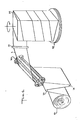
- Figure 4 is a perspective view of the stretching device incorporated in a wrapping machine by wrapping.
- the drawing device can, as a variant, be incorporated into a curtain type machine.
- a reel of stretchable plastic film 10 is unwound under a tension exerted by friction means.
- the film supply is carried out by and through a configuration of rollers 28 which ensure correct tension and alignment of the film.
- the film is then deflected through the stretching device 30 so as to allow the film to be stretched bi-axially.
- the film is kept under tension and placed around a load 24 to form a package.
- FIG. 5 is a perspective view of a double stretching device incorporated in a wrapping machine by wrapping.
- the stretched plastic film is inclined through the stretching devices 30 and 31 which are oriented with respective angles ⁇ and ⁇ equal and opposite to each other. After stretching with the device has been carried out, the film passes over a roller 10 which aligns the film to form a packaging spiral.
- the load 24 is mounted mobile on a turntable 25 so as to allow the plastic film to wrap around the load, under tension, and thus to form a helical wrapping.
- FIG. 1 also illustrates the stretching carried out on a plastic net which, when it is not stretched, comprises a rectilinear pattern 33.
- a plastic net which, when it is not stretched, comprises a rectilinear pattern 33.
- the material is inclined relative to the device 30, it is in contact with the generatrices 3. Due to the inclination of the film on the stretching device with a certain angle, the stretching between the generators is also inclined. With force stretch, comprising components in both the longitudinal and transverse directions, this bi-axial stretch distorts the pattern into a parallelogram configuration 34. Due to the stretching of the film, the base and the width of the parallelogram 34 are increased.
- the invention therefore relates first of all to an apparatus for automatically carrying out the bi-axial stretching of a plastic film
- means for supplying a film of stretchable plastic means for automatically stretching the film thus fed and means for orienting the film at a certain angle with respect to stretching means for stretching the film in its length and in its width.
- These stretching means comprise a plurality of generators, the generators being placed substantially in parallel alignment and displaced so as to define an eccentric or off-center path which comes into contact with friction and stretches the film.
- the apparatus also includes means for compensating the film along the perimeter of the stretching means such as means for axially driving the generators.
- the angle between the film and the stretching means is between 0 and 90 °.
- the apparatus also includes means for adjusting the degree of stretching across the width of the film.
- the invention also relates to an apparatus which comprises stretch film supply means, means for automatically stretching the film, the automatic stretching being carried out simultaneously in the longitudinal and transverse directions of the film to produce a bi-stretched film. axial; and means for packaging the load with the film thus stretched bi-axially.
- the stretching means includes a first stretching device having a plurality of generators placed substantially in parallel alignment, means for moving the generators along an eccentric or off-center path relative to a central axis so that the distance between the adjacent generators increase, the film being in friction contact with the adjacent generators so as to stretch the film and means for moving each generator in axial direction and in a coordinated and staggered manner to compensate for the movement of the film along the device and means for orienting the film at a certain angle relative to the stretching device to produce stretching in longitudinal and transverse directions of the film and thus stretch the film bi-axially.
- the angle between the film and the stretching device is between 0 and 90 °.
- the apparatus also comprises second means for automatically and bi-axially stretching the film, the automatic stretching being carried out in the longitudinal and transverse directions of the film.
- the apparatus further comprises a second stretching device comprising a plurality of generators placed substantially in parallel alignment, means for moving the generators along an eccentric or off-center path relative to a central axis so that the distance between the adjacent generators increase, the film being in friction contact with the adjacent generators so as to stretch the film and means for moving each generator in an axial direction and in a coordinated and staggered manner to compensate for the movement of the film along the device and means for orienting the film at a certain angle relative to the stretching device, the angle being substantially equal and opposite to the angle with which the film is oriented on the first stretching device.
- the generators of the second stretching device move on an eccentric or off-center path faster than the generators of the first stretching device.
- the eccentric or off-center path of the generators in the second stretching device has a larger perimeter than the path in the first stretching device.
- the invention relates to a product comprising a plastic film stretched bi-axially and a stretching pattern comprising a series of periodic zones and increasing variations of "NECK DOWN".
- the reasons stretching alternately comprise a series of regions in which "NECK DOWN” has been substantially prevented and regions in which "NECK DOWN” has not been substantially unhindered.
- the invention relates to a method of wrapping a load with stretchable plastic film comprising the steps of: placing an object on a support; provide stretch plastic film; tilting the film at an angle to stretching means; activate the stretching means so as to stretch the film in its length and in width and transport the stretched film around a load to form a package.
- the invention relates to a method of packaging a load with a film of stretchable plastic material comprising the steps of: placing an object on a support; Provide stretch plastic film; Activating a first stretching device comprising a plurality of generators having a substantially parallel arrangement and means for driving the generators on an eccentric or decentered path relative to a central axis as well as means for moving the generators in an axial direction and way coordinated; tilting the film through and relative to a first stretching device to stretch the film bi-axially and finally transporting the stretched film on a load to form a package.
- the method also includes the steps of: Activating a second stretching device comprising a plurality of generators having a substantially parallel arrangement and means for driving the generators in an eccentric or off-center path relative to a central axis as well as means for move the generators in an axial direction and in a coordinated manner; Incline the film from the first stretching device through the second stretching device at an angle substantially equal to and opposite the angle with which the film is oriented in the first stretching device so as to produce stretched film of bi-axial.
Abstract
Description
La présente invention concerne des procédés et appareils automatiques pour réaliser l'étirage bi-axial de matière plastique et plus particulièrement des procédés d'emballage automatiques.The present invention relates to automatic methods and apparatuses for carrying out the bi-axial drawing of plastic material and more particularly to automatic packaging methods.
Les matières plastiques sont couramment utilisées pour réaliser des emballages de protection. Par exemple, des charges devant être stockées, transportées ou distribuées peuvent nécéssiter une protection pour leur manipulation ou, contre l'environnement, etc.... Egalement, des charges à unités multiples peuvent requérir un emballage pour réaliser une charge unique et monobloc plus facilement gérable.Plastics are commonly used to make protective packaging. For example, loads to be stored, transported or distributed may require protection for their handling or, against the environment, etc. Also, loads with multiple units may require packaging to carry out a single, monoblock load. easily manageable.
On connaît principalement deux types d'emballage en matière plastique. Les emballages thermorétractables consistent à envelopper une charge puis à soumettre l'emballage à une température élevée. Cela provoque la contraction de la matière plastique qui serre ainsi la charge. Les inconvénients de ces emballages thermorétractables sont bien connus. En particulier, ils impliquent l'utilisation de moyens de chauffage coûteux en investissement et surtout en fonctionnement. De plus, le film d'emballage peut devenir rigide et ainsi cesser d'exercer la force de compression souhaitée.Two types of plastic packaging are mainly known. Heat-shrinkable packaging consists of wrapping a load and then subjecting the packaging to a high temperature. This causes the plastic to contract, thereby tightening the load. The drawbacks of these heat-shrinkable packages are well known. In particular, they involve the use of heating means which are costly in investment and especially in operation. In addition, the packaging film can become rigid and thus cease to exert the desired compressive force.
Le second type d'emballage plastique est l'emballage étirable. Dans ce cas, la charge est emballée dans un film de matière plastique étirée de manière que par contraction elle enserre la charge. La matière plastique étirée n'est pas rigide et continue de maintenir sa force de compression même si la charge reste au repos.The second type of plastic packaging is stretch packaging. In this case, the load is wrapped in a stretched plastic film so that by contraction it encloses the load. The stretched plastic is not rigid and continues to maintain its compressive force even if the load remains at rest.
Cependant, les emballages étirables actuellement connus ne sont pas sans limites. En effet, par opposition à l'emballage thermorétractable, dans lequel la contraction intervient dans la longueur et dans la largeur du film d'emballage, c'est-à-dire bi-axialement, l'emballage étirable n'est contracté que dans la direction dans laquelle il a été préalablement étiré. Compte tenu qu'un étirage simultané dans plusieurs directions implique des problèmes mécaniques considérables, la matière plastique étirable a jusqu'à présent été étirée seulement dans le sens de la longueur du film d'emballage.However, the currently known stretch wrappers are not without limits. In fact, as opposed to heat-shrinkable packaging, in which the contraction occurs in the length and in the width of the packaging film, that is to say bi-axially, the stretchable packaging is only contracted in the direction in which it was previously stretched. Since stretching in several directions simultaneously involves considerable mechanical problems, the stretchable plastic material has so far been stretched only lengthwise of the packaging film.
On connaît aujourd'hui principalement deux types de machines d'emballage à film étirable commercialisés, disponibles sur le marché. Les machines de banderolage et les machines dîtes "rideau" ou "pass through". Dans les machines de banderolage, la charge est montée pivotante ou l'alimentation en film pivote autour de la charge. Dans les machines "rideau" la charge est déplacée dans un rideau de film en matière plastique conformé en U puis soudé derrière la charge.Two types of stretch film packaging machines on the market are currently known, available on the market. Wrapping machines and machines called "curtain" or "pass through". In wrapping machines, the load is pivotally mounted or the film supply pivots around the load. In curtain machines the load is moved into a plastic film curtain shaped like a U and then welded behind the load.
Le matériau plastique considéré peut être du film continu ou encore un filet ou un matériau comportant des mailles ou équivalent. Pour la simplicité de la description, ces différentes variantes sont désignées par la suite sous le vocable film.The plastic material considered may be continuous film or else a net or a material comprising meshes or the like. For the simplicity of the description, these different variants are referred to below as the film.
Les machines d'emballage étirables utilisent différentes techiques pour réaliser l'étirage. La première technique connue est celle du freinage. Dans les machines de banderolage, cette technique consiste a freiner la bobine de film d'emballage lorsque la charge est entraînée en rotation et, de ce fait entraîne le film depuis la bobine en question. Dans les machines de type rideau, le rideau de film d'emballage est généralement réalisé entre deux bobines de film. Le freinage est appliqué sur l'une ou sur les deux bobines de film lorsque la charge coopère avec le rideau en vue de l'emballage. Des dispositifs de soudage ferment le film derrière la charge pour réaliser un emballage complet.Stretch packaging machines use different techniques to perform stretching. The first known technique is that of braking. In wrapping machines, this technique consists in braking the reel of packaging film when the load is rotated and, therefore, drives the film from the reel in question. In curtain type machines, the wrapping film curtain is generally made between two rolls of film. Braking is applied to one or both of the film reels when the load cooperates with the curtain for packaging. Welding devices close the film behind the load to achieve complete packaging.
Les dispositifs de freinage étirent le film d'emballage lorsqu'il est enroulé autour de la charge. Cet étirage produit une diminution de la largeur du film appelée habituellement "NECK-DOWN", c'est-à-dire la structure du film. Cette technique d'étirage par freinage présente un certain nombre d'inconvénients. L'étirage est irrégulier du fait des coins, des angles, ou des saillies de la charge, ce qui tend à couper le film d'emballage. Pour éviter, la rupture du film, le taux d'étirage est généralement diminué et il en résulte un emballage lâche. Enfin, compte tenu que l'étirage est principalement réalisé dans la longueur du film d'emballage, l'emballage n'exerce pas sur la charge une force de compression dans le sens transversal du film.Braking devices stretch the wrapping film when wrapped around the load. This stretching produces a reduction in the width of the film usually called "NECK-DOWN", that is to say the structure of the film. This braking stretching technique has a number of drawbacks. The stretching is irregular due to the corners, angles, or projections of the load, which tends to cut the packaging film. To avoid film breakage, the stretch rate is generally decreased and this results in loose packaging. Finally, given that stretching is mainly carried out over the length of the packaging film, the packaging does not exert on the load a compressive force in the transverse direction of the film.
Afin de surmonter certains de ces problèmes, il a été proposé une seconde technique d'étirage appelée le pré-étirage. Cette technique est décrite par exemple dans le brevet français 2 281 275. Il a été prouvé que cette technique était généralement acceptable pour produire un film en matière plastique d'emballage qui exerce une force dans la longueur du film. Compte tenu que la force nécessaire à l'étirage du film est plus grande que la force nécessaire pour s'opposer à sa contraction ultérieure, le pré-étirage du film réduit les problèmes de rupture du film résultant des saillies, coins de la charge, etc....In order to overcome some of these problems, a second stretching technique has been proposed called pre-stretching. This technique is described for example in French patent 2,281,275. It has been proven that this technique is generally acceptable for producing a plastic packaging film which exerts a force in the length of the film. Given that the force required to stretch the film is greater than the force necessary to oppose its subsequent contraction, the pre-stretching of the film reduces the problems of rupture of the film resulting from the projections, corners of the load, etc ...
Les dispositifs de pré-étirage fonctionnent en faisant passer le film de matière plastique d'emballage à étirer à travers une série de rouleaux, les rouleaux avals tournant plus vite que les rouleaux amonts. Le degré d'étirage du film entre les séries de rouleaux dépend de la différence de vitesse de rotation des rouleaux. En variante les rouleaux peuvent pivoter à même vitesse mais le rouleau aval a un diamètre plus grand que le rouleau amont. Le film ainsi étiré peut être utilisé pour l'emballage soit dans une machine de banderolage, soit dans une machine rideau. Dans certains cas, la charge se déplace à une vitesse supérieure à celle avec laquelle le film pré-étiré est fourni de sorte qu'un étirage supplémentaire du film est réalisé lorsque le film est appliqué sur la charge. Dans les dispositifs qui combinent le pré-étirage et le freinage, le "NECK-DOWN" du film intervient en deux points entre les rouleaux eux-mêmes et la charge.The pre-stretching devices operate by passing the plastic packaging film to be stretched through a series of rollers, the downstream rollers rotating faster than the upstream rollers. The degree of stretching of the film between the series of rollers depends on the difference in speed of rotation of the rollers. As a variant, the rollers can pivot at the same speed but the downstream roller has a larger diameter than the upstream roller. The film thus stretched can be used for packaging either in a wrapping machine or in a curtain machine. In some cases, the load moves at a higher speed than that with which the pre-stretched film is supplied so that additional stretching of the film is produced when the film is applied to the load. In devices that combine pre-stretching and braking, the "NECK-DOWN" of the film occurs at two points between the rollers themselves and the load.
Une caractéristique commune des machines et dispositifs précédemment décrits est l'étirage unidirectionnel, c'est-à-dire l'étirage du film dans sa longueur. Bien que le pré-étirage réduise les problèmes de rupture et procure un emballage plus serré, l'étirage n'est réalisé que le long de l'axe du film. Compte tenu que les utilisateurs souhaitent une contraction bi-axiale du film ainsi que cela est obtenu avec le film rétractable, il serait avantageux de procurer un procédé et un appareil pour réaliser l'étirage du film en matière plastique dans deux directions : la longueur et la largeur. De tels films ainsi étirés de façon bi-axiale exerçeraient des forces de contraction plus uniformes sur les charges emballées et particulièrement sur les charges de forme irrégulière. De plus, un "NECK-DOWN" uniforme ne permet pas de réaliser les compensations nécessaires pour les saillies, coins, etc.... En conséquence, il serait également avantageux d'avoir un "NECK-DOWN" non uniforme. Par conséquent, l'invention a pour objet un appareil pour l'étirage bi-axial de film en matière plastique et un procédé pour utiliser un tel appareil.A common characteristic of the machines and devices described above is the unidirectional stretching, that is to say the stretching of the film in its length. Although pre-stretching reduces breakage problems and provides tighter packaging, stretching is only done along the axis of the film. Given that users want a bi-axial contraction of the film as is achieved with the shrink film, it would be advantageous to provide a method and an apparatus for drawing the plastic film in two directions: the length and the width. Such films thus stretched bi-axially would exert more uniform contraction forces on the packaged loads and particularly on the irregularly shaped loads. In addition, a uniform "NECK-DOWN" does not allow the necessary compensations to be made for the projections, corners, etc.. Consequently, it would also be advantageous to have a non-uniform "NECK-DOWN". Consequently, the subject of the invention is an apparatus for the bi-axial stretching of plastic film and a method for using such an apparatus.
L'invention a également pour objet de produire un emballage mettant en oeuvre un film en matière plastique étiré de façon bi-axiale.The invention also aims to produce a packaging using a plastic film stretched bi-axially.
L'invention a également pour objet de procurer un film en matière plastique étiré de façon bi-axiale qui n'a pas un "NECK-DOWN" uniforme.The object of the invention is also to provide a bi-axially stretched plastic film which does not have a uniform "NECK-DOWN".
L'invention concerne un appareil nouveau et sa mise en oeuvre dans un procédé pour réaliser automatiquement l'étirage d'un film en matière plastique. Pour résoudre les problèmes mentionnés précédemment, le film en matière plastique est étiré périodiquement à la fois dans sa longueur et dans sa largeur. Un emballage réalisé à partir d'une machine utilisant l'invention n'exerce pas des forces de compression seulement dans la longueur de film mais aussi dans la largeur du film. Du fait que l'étirage est réalisé essentiellement avant que le film ne soit appliqué sur la charge, les problèms de rupture sont réduits.The invention relates to a new apparatus and its implementation in a method for automatically carrying out the stretching of a plastic film. To solve the aforementioned problems, the plastic film is stretched periodically both in length and in its width. A packaging produced from a machine using the invention does not exert compressive forces only in the length of film but also in the width of the film. Due to the fact that stretching is carried out essentially before the film is applied to the load, the problems of rupture are reduced.
De plus, étant donné que le film n'est pas étiré de façon uniforme, il est possible d'avoir les compensations nécessaires pour les saillies et les coins qui sinon sont la source de rupture du film. En conséquence, les opérations d'emballage peuvent être plus rapides et la charge est mieux emballée. L'invention est particulièrement utile si la charge comprend plusieurs objets devant être groupés ou si la charge doit rester au repos.In addition, since the film is not stretched uniformly, it is possible to have the necessary compensations for the projections and corners which otherwise are the source of the film breaking. As a result, packaging operations can be faster and the load is better packaged. The invention is particularly useful if the load comprises several objects to be grouped or if the load must remain at rest.
L'invention implique la mise en oeuvre de génératrices d'étirage du film en matière plastique ainsi qu'il est décrit dans le brevet US 546 034, et dans le brevet français 74 27653, publié sous le n° 2 281 275 ainsi que dans son addition n° 83 1284. Contrairement à ce qui est décrit dans le brevet français 74 27653, publié sous le n° 2 281 275 ainsi que dans son addition n° 83 1284, la présente invention réalise l'étirage du film en matière plastique à la fois dans sa longueur et dans sa largeur.The invention involves the use of stretching generators for the plastic film as described in US patent 546,034, and in French patent 74 27653, published under No. 2,281,275 as well as in its addition No. 83 1284. Contrary to what is described in French patent 74 27653, published under No. 2 281 275 as well as in its addition No. 83 1284, the present invention achieves the stretching of the plastic film both in length and in width.
L'invention concerne un dispositif d'étirage comprenant une pluralité de génératrices placées substantiellement parallèlement par rapport à un axe de rotation; des moyens d'entraînement des génératrices le long d'un chemin décentré ou formant excentrique par rapport à un axe central; et des moyens pour entraîner les génératrices dans les directions axiales, de façon échelonnée et coordonnée. Le nombre de génératrices est préférentiellement compris entre six et huit, mais d'autres possibilités sont envisageables.The invention relates to a drawing device comprising a plurality of generators placed substantially parallel with respect to an axis of rotation; means for driving the generators along an off-center path or forming an eccentric with respect to a central axis; and means for driving the generators in the axial directions, in a staggered and coordinated manner. The number of generators is preferably between six and eight, but other possibilities are possible.
Dans un appareil automatique d'étirage de film, le dispositif est mis en oeuvre pour réaliser un motif d'étirage bi-axial sur le film. Un appareil comprend des moyens d'alimentation en film en matière plastique étirable, des moyens pour étirer automatiquement le film ainsi fourni, et des moyens pour orienter le film fourni avec un certain angle par rapport aux moyens d'étirage pour étirer le film à la fois dans le sens de sa longueur et dans le sens de sa largeur.In an automatic film stretching device, the device is used to produce a bi-axial stretching pattern on the film. An apparatus comprises means for supplying plastic stretch film, means for automatically stretching the film thus supplied, and means for orienting the supplied film at an angle to the stretching means for stretching the film both lengthwise and in the sense of its width.
Dans une forme de réalisation possible, le film est également placé avec un certain angle et partiellement autour d'un second appareil d'étirage orienté par rapport au film avec un angle qui est essentiellement égal et opposé à l'angle du premier dispositif d'étirage.In a possible embodiment, the film is also placed at a certain angle and partially around a second stretching apparatus oriented with respect to the film with an angle which is essentially equal to and opposite the angle of the first device. drawing.
Comme le matériau est en contact avec les génératrices, la distance entre les génératrices et l'axe central est augmentée, et le matériau entre les génératrices est donc étiré. Du fait que le film intercepte le dispositif avec un certain angle, l'étirage forme un certain angle par rapport à la longueur et à la largeur du film. La proportion d'étirage dans chaque direction dépend de l'angle d'intersection entre le film et le dispositif d'étirage. Lorsque le film passe à travers et partiellement autour du dispositif d'étirage rotatif, les génératrices changent de position axiale. Cela compense la tendance du film ainsi dévié de glisser ou de se déplacer ou de changer d'orientation par rapport au dispositif d'étirage.As the material is in contact with the generators, the distance between the generators and the central axis is increased, and the material between the generators is therefore stretched. Because the film intercepts the device at a certain angle, the stretching forms an angle with respect to the length and width of the film. The proportion of stretching in each direction depends on the angle of intersection between the film and the stretching device. When the film passes through and partially around the rotary stretching device, the generators change their axial position. This compensates for the tendency of the film thus deflected to slide or move or change orientation relative to the stretching device.
Après engagement avec le film, les génératrices se déplacent d'un côté à l'autre du dispositif d'étirage. La distance sur laquelle les génératrices se déplacent dans la direction axiale dépend de l'angle d'intersection entre le film en matière plastique et le dispositif.After engagement with the film, the generators move from one side to the other of the stretching device. The distance over which the generators move in the axial direction depends on the angle of intersection between the plastic film and the device.
Le procédé pour mettre en oeuvre l'invention à l'emballage d'une charge avec un film en matière plastique comprend les étapes suivantes : on place un objet sur un support, on fournit du film en matière plastique étirable et on incline le film par rapport aux moyens d'étirage, on active les moyens d'étirage pour étirer le film dans le sens de la longueur et le sens de la largeur du film et on forme un emballage. Du fait du frottement à l'intersection entre le film en matière plastique et les génératrices, la tendance du film au "NECK DOWN" lors de l'étirage est diminuée. Cependant entre les zones d'intersection le film peut être sujet à un certain "NECK DOWN". Cela conduit à un film qui présente un motif d'étirage qui correspond à ces zones d'intersection. Le produit, selon l'invention comprend donc un film en matière plastique étiré de façon bi-axiale et un motif d'étirage comprenant une série de zones périodiques et en augmentation dans lesquelles le film a été substantiellement empêché et des régions dans lesquelles le "NECK DOWN" a été substantiellement non empêché.The method for implementing the invention in the packaging of a load with a plastic film comprises the following steps: an object is placed on a support, provision is made of stretchable plastic film and the film is tilted by relative to the stretching means, the stretching means are activated to stretch the film lengthwise and widthwise of the film and a package is formed. Of makes friction at the intersection between the plastic film and the generators, the tendency of the film to "NECK DOWN" during stretching is reduced. However between the areas of intersection the film may be subject to a certain "NECK DOWN". This results in a film which has a stretch pattern which corresponds to these intersection areas. The product according to the invention therefore comprises a plastic film stretched bi-axially and a stretching pattern comprising a series of periodic and increasing zones in which the film has been substantially prevented and regions in which the " NECK DOWN "was substantially not prevented.
L'étirage dans la direction transversale du film peut être augmenté en utilisant deux dispositifs d'étirage qui superposent le motif du premier dispositif d'étirage au second motif du dispositif correspondant. L'entraînement du film à travers le second dispositif d'étirage a un angle qui est approximativement égal à l'opposé de l'angle sur le premier dispositif d'étirage procure un motif d'étirage dans une direction opposée à celle précédemment obtenue. Cela tend à maximiser l'étirage le long des axes du film. Naturellement, la valeur de l'angle peut être adaptée pour correspondre à la demande de chaque application particulièreThe stretch in the transverse direction of the film can be increased by using two stretching devices which superimpose the pattern of the first stretching device on the second pattern of the corresponding device. Driving the film through the second stretching device at an angle which is approximately equal to the opposite of the angle on the first stretching device provides a stretching pattern in a direction opposite to that previously obtained. This tends to maximize the stretch along the axes of the film. Naturally, the value of the angle can be adapted to match the demand of each particular application.
L'invention sera bien comprise grâce à la description qui suivra en référence aux dessins annexés dans lesquels:
- - La figure 1 est une vue en perspective d'un dispositif d'étirage avec le film d'étirage monté dessus.
- - La figure 2 est une vue de côté du dispositif d'étirage avec le film en matière plastique monté dessus.
- - La figure 3 est une vue de côté interne illustrant une came du dispositif.
- - La figure 4 est une vue en perspective d'un dispositif d'étirage associé à une machine d'emballage par banderolage.
- - La figure 5 est une vue en perspective de deux dispositifs d'étirage associés à une machine d'emballage par banderolage.
- - Figure 1 is a perspective view of a stretching device with the stretching film mounted thereon.
- - Figure 2 is a side view of the stretching device with the plastic film mounted thereon.
- - Figure 3 is an internal side view illustrating a cam of the device.
- - Figure 4 is a perspective view of a stretching device associated with a wrapping machine by wrapping.
- - Figure 5 is a perspective view of two stretching devices associated with a wrapping machine by wrapping.
On se régère à la figure 1 sur laquelle est représentée un dispositif d'étirage dans lequel un film en matière plastique 1 est étiré pour former un film en matière plastique 2 étiré. Le film 1 est orienté en oblique c'est-à-dire incliné à travers une d'une série de génératrices 3 placées substantiellement parallèlement les unes aux autres et situées dans des fentes radiales 4. Les fentes 4 sont ménagées dans des disques 5, 6 coaxiaux et écartés l'un de l'autre. Les fentes 4 autorisent les génératrices 3 à se déplacer dans une direction perpendiculaire à l'axe de rotation. En conséquence, la distance entre les génératrices 3 peut être modifiée tout en gardant un parallélisme substantiel entre les génératrices. Les disques 5, 6 sont montés en rotation sur un arbre moteur 7 qui définit l'axe de rotation, de manière à venir en prise avec le film ou faire avancer le film sur la configuration de génératrices 3.We refer to Figure 1 on which is represented a stretching device in which a
La première génératrice 3a est située à proximité de l'arbre moteur 7 au moment ou le film en matière plastique vient au contact pour la première fois avec un certain angle par rapport à la génératrice. Du fait que les disques 5 et 6 pivotent le film 1 est entraîné jusqu'à la deuxième génératrice 3b puis jusqu'à la génératrice 3c et ainsi de suite. Simultanément, les génératrices 3 sont déplacées le long d'un chemin radial défini par des fentes 4 de manière que la distance entre les génératrices adjacentes soit augmentée.The first generator 3a is located near the drive shaft 7 when the plastic film comes into contact for the first time at a certain angle relative to the generator. Because the discs 5 and 6 pivot the
La première génératrice 3a est déplacée simultanément dans une direction axiale, c'est-à-dire parallèle à l'arbre moteur 7 de manière à compenser la tendance du film en matière plastique de glisser ou se déplacer le long du dispositif d'étirage rotatif. Chaque génératrice se déplace de façon échelonnée et coordonnée avec les autres génératrices du dispositif. Cette coordination du mouvement axial des génératrices 3 est illustrée par les positions occupées par les génératrices durant un cycle correspondant à une révolution du dispositif d'étirage. Après environ une demi-révolution, les génératrices atteignent leur point le plus éloigné de l'arbre moteur 7 et le mouvement dans la direction axiale est alors à son maximum. Lorsque la rotation continue, le contact entre les génératrices et le film en matière plastique 16 cesse et les génératrices reviennent à leur position proche de l'arbre moteur 7 et dans la direction axiale opposée en vue de recommencer un autre cycle.The first generator 3a is moved simultaneously in an axial direction, that is to say parallel to the motor shaft 7 so as to compensate for the tendency of the plastic film to slide or move along the rotary stretching device . Each generator moves in a staggered and coordinated manner with the other generators of the device. This coordination of the axial movement of the
La figure 2 illustre comment la rotation des génératrices sur un chemin axial produit l'étirage du film. Lorsque le disque 6 est entraîné autour de l'arbre moteur 7 les génératrices 3 sont déplacées le long du chemin radial défini par les fentes 4 qui permet de faire varier la distance entre les génératrices adjacentes. Ainsi, comme le film en matière plastique initialement est en contact avec les génératrices, la distance 11 est inférieure ou égale à la distance 12. De la même manière, la distance 13 est supérieure à la distance 12 et inférieure à la distance 14. Lorsque les génératrices sont à leur extension maximale, la distance 11 est augmentée jusqu'à la distance 15 et la distance 16 augmentée jusqu'à la distance 18. La rotation des génératrices pour provoquer leur déplacement sur un chemin excentrique ou décentré provoque donc l'étirage du film en matière plastique qui devient distordu et étiré. Les distances 11, 12, 13, 14 et 15 mentionnées correspondent aux positions des génératrices sur les chemins radiaux c'est-à-dire à la distance entre les génératrices 3 et l'arbre moteur 7. Les distances 16 et 18 sont des écartements entre deux génératrices adjacentes respectivement au début et à la fin de l'étirage.Figure 2 illustrates how the rotation of the generators on an axial path produces the stretching of the film. When the disc 6 is driven around the drive shaft 7 the
La figure 3 est une vue en coupe du dispositif d'étirage. Les génératrices 3 sont placées de manière à traverser les disques 5 et 6 à travers les fentes 4. Les génératrices sont placées à proximité de la surface d'une came 21. Un insert 19 court dans un canal 20 de manière à assujettir les génératrices à la came 21. La rotation des génératrices 3 autour de la came 21 produit le cheminement excentrique des génératrices. Ce mouvement est réalisé grâce à un moteur 23 qui entraîne les disques 5 et 6 sur la came. De plus, une fente 22 forme une hélice autour de la came de manière à provoquer le déplacement des génératrices de la position 8 à la position 9 puis le retour de la position 9 à la position 8 c'est-à-dire le mouvement axial des génératrices. Afin de diminuer les forces de frottement, les génératrices sont montées de manière à pivoter dans des roulements à billes.Figure 3 is a sectional view of the stretching device. The
La figure 4 est une vue en perspective du dispositif d'étirage incorporé à une machine d'emballage par banderolage. Le dispositif d'étirage peut, en variante, être incorporé à une machine de type rideau. Une bobine de film en matière plastique étirable 10 est déroulée sous une tension exercée par des moyens de friction. L'alimentation en film est réalisée par et à travers une configuration de rouleaux 28 qui assurent une tension correcte et un alignement du film. Le film est ensuite dévié à travers le dispositif d'étirage 30 de manière à permettre au film d'être étiré de façon bi-axiale.Figure 4 is a perspective view of the stretching device incorporated in a wrapping machine by wrapping. The drawing device can, as a variant, be incorporated into a curtain type machine. A reel of
Le film et maintenu sous tension et placé autour d'une charge 24 pour former un emballage.The film is kept under tension and placed around a
La figure 5 est une vue en perspective d'un double dispositif d'étirage incorporé à une machine d'emballage par banderolage. Ici encore, une application à une machine de type rideau est également possible. Le film en matière plastique tendu est incliné à travers les dispositifs d'étirage 30 et 31 qui sont orientés avec des angles respectivements α et β égaux et opposés l'un à l'autre. Après que l'étirage avec le dispositif ait été réalisé, le film passe sur un rouleau 10 qui réalise l'alignement du film pour former une spirale d'emballage. La charge 24 est montée mobile sur une table tournante 25 de manière à permettre au film en matière plastique de s'enrouler autour de la charge, sous tension, et ainsi de former un banderolage hélicoïdal.Figure 5 is a perspective view of a double stretching device incorporated in a wrapping machine by wrapping. Here again, an application to a curtain type machine is also possible. The stretched plastic film is inclined through the stretching
La figure 1 illustre également l'étirage réalisé sur un filet en matière plastique qui, lorsqu'il n'est pas étiré, comporte un motif rectiligne 33. Comme le matériau est incliné par rapport au dispositif 30, il est en contact avec les génératrices 3. Du fait de l'inclinaison du film sur le dispositif d'étirage avec un certain angle, l'étirage entre les génératrices est également incliné. Avec une force d'étirage, comprenant des composantes à la fois dans les directions longitudinales et transversales, cet étirage bi-axial distord le motif en une configuration en parallèlogramme 34. Du fait de l'étirage du film, la base et la largeur du parallèlogramme 34 sont augmentées.FIG. 1 also illustrates the stretching carried out on a plastic net which, when it is not stretched, comprises a rectilinear pattern 33. As the material is inclined relative to the
L'invention concerne donc d'abord un appareil pour réaliser automatiquement l'étirage bi-axial d'un film en matière plastique comprenant des moyens d'alimentation en film en matière plastique étirable, des moyens pour étirer automatiquement le film ainsi alimenté et des moyens pour orienter le film avec un certain angle par rapport à des moyens d'étirage pour étirer le film dans sa longueur et dans sa largeur. Ces moyens d'étirage comprennent une pluralité de génératrices, les génératrices étant placées substantiellement en alignement parallèle et déplacées de manière à définir un chemin excentrique ou décentré qui vient au contact avec friction et étire le film. L'appareil comprend également des moyens de compensation du film le long du périmètre des moyens d'étirage tels que des moyens d'entraînement axial des génératrices. L'angle entre le film et les moyens d'étirage est compris entre 0 et 90°. L'appareil comprend également des moyens pour régler le degré d'étirage dans la largeur du film.The invention therefore relates first of all to an apparatus for automatically carrying out the bi-axial stretching of a plastic film comprising means for supplying a film of stretchable plastic, means for automatically stretching the film thus fed and means for orienting the film at a certain angle with respect to stretching means for stretching the film in its length and in its width. These stretching means comprise a plurality of generators, the generators being placed substantially in parallel alignment and displaced so as to define an eccentric or off-center path which comes into contact with friction and stretches the film. The apparatus also includes means for compensating the film along the perimeter of the stretching means such as means for axially driving the generators. The angle between the film and the stretching means is between 0 and 90 °. The apparatus also includes means for adjusting the degree of stretching across the width of the film.
L'invention concerne également un appareil qui comprend des moyens d'alimentation en film étirable, des moyens pour étirer automatiquement le film, l'étirage automatique étant réalisé simultanément dans les directions longitudinale et transversale du film pour produire un film étiré de façon bi-axiale; et des moyens pour emballer la charge avec le film ainsi étiré de façon bi-axiale. Les moyens d'étirage comprennent un premier dispositif d'étirage ayant une pluralité de génératrices placées substantiellement en alignement parallèle, des moyens pour déplacer les génératrices le long d'un chemin excentrique ou décentré par rapport à un axe central de manière que la distance entre les génératrices adjacentes augmentent, le film étant en contact avec friction avec les génératrices adjacentes de manière à étirer le film et des moyens pour déplacer chaque génératrice en direction axiale et de façon coordonnée et échelonnée pour compenser le mouvement du film le long du dispositif et des moyens pour orienter le film avec un certain angle par rapport au dispositif d'étirage pour produire l'étirage dans des directions longitudinale et transversale du film et ainsi étirer de façon bi-axiale le film. L'angle entre le film et le dispositif d'étirage est compris entre 0 et 90°. L'appareil comprend également des seconds moyens pour étirer automatiquement et de façon bi-axial le film, l'étirage automatique étant réalisé dans les directions longitudinale et transversale du film. L'appareil comporte en outre un second dispositif d'étirage comprenant une pluralité de génératrices placées substantiellement en alignement parallèle, des moyens pour déplacer les génératrices le long d'un chemin excentrique ou décentré par rapport à un axe central de manière que la distance entre les génératrices adjacentes augmentent, le film étant en contact avec friction avec les génératrices adjacentes de manière à étirer le film et des moyens pour déplacer chaque génératrice en direction axiale et de façon coordonnée et échelonnée pour compenser le mouvement du film le long du dispositif et des moyens pour orienter le film avec un certain angle par rapport au dispositif d'étirage, l'angle étant substantiellement égal et opposé à l'angle avec lequel le film est orienté sur le premier dispositif d'étirage. Les génératrices du second dispositif d'étirage se déplacent sur un chemin excentrique ou décentré plus vite que les génératrices du premier dispositif d'étirage. Le chemin excentrique ou décentré des génératrices dans le second dispositif d'étirage a un périmètre plus grand que le chemin dans le premier dispositif d'étirage. La charge est emballée de manière que le film en matière plastique étiré de façon bi-axiale est appliqué sur la surface d'une charge à une vitesse supérieure à la vitesse à laquelle le film passe sur le second dispositif d'étirage.The invention also relates to an apparatus which comprises stretch film supply means, means for automatically stretching the film, the automatic stretching being carried out simultaneously in the longitudinal and transverse directions of the film to produce a bi-stretched film. axial; and means for packaging the load with the film thus stretched bi-axially. The stretching means includes a first stretching device having a plurality of generators placed substantially in parallel alignment, means for moving the generators along an eccentric or off-center path relative to a central axis so that the distance between the adjacent generators increase, the film being in friction contact with the adjacent generators so as to stretch the film and means for moving each generator in axial direction and in a coordinated and staggered manner to compensate for the movement of the film along the device and means for orienting the film at a certain angle relative to the stretching device to produce stretching in longitudinal and transverse directions of the film and thus stretch the film bi-axially. The angle between the film and the stretching device is between 0 and 90 °. The apparatus also comprises second means for automatically and bi-axially stretching the film, the automatic stretching being carried out in the longitudinal and transverse directions of the film. The apparatus further comprises a second stretching device comprising a plurality of generators placed substantially in parallel alignment, means for moving the generators along an eccentric or off-center path relative to a central axis so that the distance between the adjacent generators increase, the film being in friction contact with the adjacent generators so as to stretch the film and means for moving each generator in an axial direction and in a coordinated and staggered manner to compensate for the movement of the film along the device and means for orienting the film at a certain angle relative to the stretching device, the angle being substantially equal and opposite to the angle with which the film is oriented on the first stretching device. The generators of the second stretching device move on an eccentric or off-center path faster than the generators of the first stretching device. The eccentric or off-center path of the generators in the second stretching device has a larger perimeter than the path in the first stretching device. The load is wrapped so that the bi-axially stretched plastic film is applied to the surface of a load at a speed greater than the speed at which the film passes over the second stretching device.
L'invention concerne en troisième lieu un produit comprenant un film en matière plastique étiré de façon bi-axiale et un motif d'étirage comprenant une série de zones périodiques et en augmentation de variations de "NECK DOWN". Les motifs d'étirage comprennent alternativement une série de régions dans lesquelles le "NECK DOWN" a été substantiellement empêché et des régions dans lesquelles le "NECK DOWN" n'a pas été substantiellement non empêché.Thirdly, the invention relates to a product comprising a plastic film stretched bi-axially and a stretching pattern comprising a series of periodic zones and increasing variations of "NECK DOWN". The reasons stretching alternately comprise a series of regions in which "NECK DOWN" has been substantially prevented and regions in which "NECK DOWN" has not been substantially unhindered.
L'invention concerne en quatrième lieu un procédé d'emballage d'une charge avec du film en matière plastique étirable comprennant les étapes consistant à : placer un objet sur un support; fournir du film en matière plastique étirable; incliner le film avec un certain angle par rapport à des moyens d'étirage; activer les moyens d'étirage de manière à étirer le film dans sa longueur et dans largeur et transporter le film étiré autour d'une charge pour former un emballage.Fourthly, the invention relates to a method of wrapping a load with stretchable plastic film comprising the steps of: placing an object on a support; provide stretch plastic film; tilting the film at an angle to stretching means; activate the stretching means so as to stretch the film in its length and in width and transport the stretched film around a load to form a package.
Plus précisément, l'invention concerne un procédé d'emballage d'une charge avec du film en matière plastique étirable comprenant les étapes consistant à : Placer un objet sur un support; Fournir du film en matière plastique étirable; Activer un premier dispositif d'étirage comprenant une pluralité de génératrices ayant une disposition substantiellement parallèle et des moyens pour entraîner les génératrices sur un chemin excentrique ou décentré par rapport à un axe central ainsi que des moyens pour déplacer les génératrices dans une direction axiale et façon coordonnée; incliner le film à travers et par rapport à un premier dispositif d'étirage pour étirer le film de façon bi-axiale et enfin transporter le film étiré sur une charge pour former un emballage. Le procédé comprend également les étapes consistant à : Activer un second dispositif d'étirage comprenant une pluralité de génératrices ayant une disposition substantiellement parallèle et des moyens pour entraîner les génératrices dans un chemin excentrique ou décentré par rapport à un axe central ainsi que des moyens pour déplacer les génératrices dans une direction axiale et de façon coordonnée; Incliner le film depuis le premier dispositif d'étirage à travers le second dispositif d'étirage avec un angle substantiellement égal et opposé à l'angle avec lequel le film est orienté dans le premier dispositif d'étirage de manière à produire du film étiré de façon bi-axiale.More specifically, the invention relates to a method of packaging a load with a film of stretchable plastic material comprising the steps of: placing an object on a support; Provide stretch plastic film; Activating a first stretching device comprising a plurality of generators having a substantially parallel arrangement and means for driving the generators on an eccentric or decentered path relative to a central axis as well as means for moving the generators in an axial direction and way coordinated; tilting the film through and relative to a first stretching device to stretch the film bi-axially and finally transporting the stretched film on a load to form a package. The method also includes the steps of: Activating a second stretching device comprising a plurality of generators having a substantially parallel arrangement and means for driving the generators in an eccentric or off-center path relative to a central axis as well as means for move the generators in an axial direction and in a coordinated manner; Incline the film from the first stretching device through the second stretching device at an angle substantially equal to and opposite the angle with which the film is oriented in the first stretching device so as to produce stretched film of bi-axial.
Claims (21)
Priority Applications (1)
| Application Number | Priority Date | Filing Date | Title |
|---|---|---|---|
| AT86400938T ATE66861T1 (en) | 1985-04-29 | 1986-04-29 | METHOD AND DEVICE FOR BIAXIAL STRETCHING OF PLASTIC MATERIALS AND PRODUCTS MADE SO. |
Applications Claiming Priority (2)
| Application Number | Priority Date | Filing Date | Title |
|---|---|---|---|
| US72822085A | 1985-04-29 | 1985-04-29 | |
| US728220 | 1985-04-29 |
Publications (3)
| Publication Number | Publication Date |
|---|---|
| EP0213969A2 true EP0213969A2 (en) | 1987-03-11 |
| EP0213969A3 EP0213969A3 (en) | 1988-10-19 |
| EP0213969B1 EP0213969B1 (en) | 1991-09-04 |
Family
ID=24925916
Family Applications (1)
| Application Number | Title | Priority Date | Filing Date |
|---|---|---|---|
| EP86400938A Expired - Lifetime EP0213969B1 (en) | 1985-04-29 | 1986-04-29 | Process and apparatus for biaxially stretching plastics materials, and products thereby obtained |
Country Status (4)
| Country | Link |
|---|---|
| US (1) | US5040356A (en) |
| EP (1) | EP0213969B1 (en) |
| AT (1) | ATE66861T1 (en) |
| DE (1) | DE3681235D1 (en) |
Cited By (1)
| Publication number | Priority date | Publication date | Assignee | Title |
|---|---|---|---|---|
| EP0392000A1 (en) * | 1988-10-10 | 1990-10-17 | Francis Ian Down | Pre-stretching wrapping film |
Families Citing this family (24)
| Publication number | Priority date | Publication date | Assignee | Title |
|---|---|---|---|---|
| US5203136A (en) * | 1989-09-06 | 1993-04-20 | Newtec International (Societe Anonyme) | Film unwinding carriage for a packaging machine |
| FR2651481B1 (en) * | 1989-09-06 | 1991-12-20 | Newtec Int | FILM RELEASE TROLLEY FOR PACKAGING MACHINE. |
| CA2068908C (en) * | 1992-05-19 | 2000-06-27 | Donald J. Salzsauler | Stretch film |
| CA2228020C (en) * | 1997-07-30 | 2006-03-28 | Donald J. Salzsauler | Method and apparatus for producing coreless rolls of sheet material |
| US7568327B2 (en) | 2003-01-31 | 2009-08-04 | Lantech.Com, Llc | Method and apparatus for securing a load to a pallet with a roped film web |
| US20050150811A1 (en) * | 2004-01-08 | 2005-07-14 | Mulch Manufacturing, Inc. | Method for wrapping product |
| US7707801B2 (en) * | 2005-04-08 | 2010-05-04 | Lantech.Com, Llc | Method for dispensing a predetermined amount of film relative to load girth |
| AU2007221338A1 (en) | 2006-02-23 | 2007-09-07 | Lantech.Com, Llc | Method and apparatus for securing a load to a pallet with a roped film web |
| US9908648B2 (en) * | 2008-01-07 | 2018-03-06 | Lantech.Com, Llc | Demand based wrapping |
| WO2009089279A1 (en) * | 2008-01-07 | 2009-07-16 | Lantech. Com, Llc | Electronic control of metered film dispensing in a wrapping apparatus |
| IT1395323B1 (en) * | 2009-08-28 | 2012-09-14 | Gd Spa | EQUIPMENT FOR FEEDING TAPE MATERIAL IN PACKAGING MACHINES |
| WO2012058596A1 (en) | 2010-10-29 | 2012-05-03 | Lantech.Com, Llc | Machine generated wrap data |
| WO2014066757A1 (en) | 2012-10-25 | 2014-05-01 | Lantech.Com, Llc | Rotation angle-based wrapping |
| CA2889579C (en) | 2012-10-25 | 2020-07-14 | Lantech.Com, Llc | Corner geometry-based wrapping |
| CA3109066C (en) | 2012-10-25 | 2023-03-07 | Lantech.Com, Llc | Effective circumference-based wrapping |
| CA2901256C (en) | 2013-02-13 | 2017-12-12 | Lantech.Com, Llc | Containment force-based wrapping |
| US9896229B1 (en) | 2013-08-29 | 2018-02-20 | Top Tier, Llc | Stretch wrapping apparatus and method |
| CA3038441C (en) | 2014-01-14 | 2021-04-27 | Lantech.Com, Llc | Dynamic adjustment of wrap force parameter responsive to monitored wrap force and/or for film break reduction |
| WO2016057724A1 (en) | 2014-10-07 | 2016-04-14 | Lantech.Com, Llc | Graphical depiction of wrap profile for load wrapping apparatus |
| CA2999861C (en) | 2015-09-25 | 2020-05-05 | Lantech.Com, Llc | Stretch wrapping machine with automated determination of load stability by subjecting a load to a disturbance |
| AU2018338049B2 (en) | 2017-09-22 | 2021-12-23 | Lantech.Com, Llc | Load wrapping apparatus wrap profiles with controlled wrap cycle interruptions |
| CA3106566C (en) | 2018-08-06 | 2023-04-04 | Lantech.Com, Llc | Stretch wrapping machine with curve fit control of dispense rate |
| AU2020346736B2 (en) | 2019-09-09 | 2024-02-22 | Lantech.Com, Llc | Stretch wrapping machine with dispense rate control based on sensed rate of dispensed packaging material and predicted load geometry |
| CA3147093A1 (en) | 2019-09-19 | 2021-03-25 | Iii Patrick R. Lancaster | Packaging material grading and/or factory profiles |
Citations (6)
| Publication number | Priority date | Publication date | Assignee | Title |
|---|---|---|---|---|
| LU55225A1 (en) * | 1967-01-06 | 1968-03-27 | ||
| US3441638A (en) * | 1964-11-20 | 1969-04-29 | Smith & Nephew | Process for making an open network structure |
| FR2026328A1 (en) * | 1968-12-17 | 1970-09-18 | Fmc Corp | |
| US3833973A (en) * | 1972-06-16 | 1974-09-10 | Kimberly Clark Co | Simultaneous continuous biaxial web stretcher |
| FR2281275A1 (en) * | 1974-08-08 | 1976-03-05 | Thimon | Stretching film just prior to wrapping goods in oriented film - to avoid interaction between pack stability and stretching forces |
| EP0110751A1 (en) * | 1982-10-29 | 1984-06-13 | Newtec International | Stretching device |
Family Cites Families (6)
| Publication number | Priority date | Publication date | Assignee | Title |
|---|---|---|---|---|
| US2505146A (en) * | 1946-12-14 | 1950-04-25 | Polaroid Corp | Process and apparatus for stretching continuous sheet materials |
| US2571355A (en) * | 1948-07-07 | 1951-10-16 | Wingfoot Corp | Method and apparatus for simultaneous two-way stretching of film |
| DK103913C (en) * | 1963-08-08 | 1966-03-07 | Ole-Bendt Rasmussen | Method for imparting a web of a orientable polymeric material a transverse stretch, and roll for use in the method. |
| US4140827A (en) * | 1977-06-29 | 1979-02-20 | Compo Industries Inc. | Imitation-leather, bias-stretching process |
| US4302920A (en) * | 1979-11-21 | 1981-12-01 | Lantech Inc. | Film web drive stretch wrapping apparatus and process |
| US4458467A (en) * | 1981-03-31 | 1984-07-10 | Infra Pak (Dallas), Inc. | Pretensioner for stretchable film web with dancer roller compensation |
-
1986
- 1986-04-29 EP EP86400938A patent/EP0213969B1/en not_active Expired - Lifetime
- 1986-04-29 DE DE8686400938T patent/DE3681235D1/en not_active Expired - Fee Related
- 1986-04-29 AT AT86400938T patent/ATE66861T1/en not_active IP Right Cessation
-
1987
- 1987-10-06 US US07/107,849 patent/US5040356A/en not_active Expired - Fee Related
Patent Citations (6)
| Publication number | Priority date | Publication date | Assignee | Title |
|---|---|---|---|---|
| US3441638A (en) * | 1964-11-20 | 1969-04-29 | Smith & Nephew | Process for making an open network structure |
| LU55225A1 (en) * | 1967-01-06 | 1968-03-27 | ||
| FR2026328A1 (en) * | 1968-12-17 | 1970-09-18 | Fmc Corp | |
| US3833973A (en) * | 1972-06-16 | 1974-09-10 | Kimberly Clark Co | Simultaneous continuous biaxial web stretcher |
| FR2281275A1 (en) * | 1974-08-08 | 1976-03-05 | Thimon | Stretching film just prior to wrapping goods in oriented film - to avoid interaction between pack stability and stretching forces |
| EP0110751A1 (en) * | 1982-10-29 | 1984-06-13 | Newtec International | Stretching device |
Cited By (2)
| Publication number | Priority date | Publication date | Assignee | Title |
|---|---|---|---|---|
| EP0392000A1 (en) * | 1988-10-10 | 1990-10-17 | Francis Ian Down | Pre-stretching wrapping film |
| EP0392000A4 (en) * | 1988-10-10 | 1991-12-18 | G.D. Engineering Pty Limited | Pre-stretching wrapping film |
Also Published As
| Publication number | Publication date |
|---|---|
| EP0213969B1 (en) | 1991-09-04 |
| EP0213969A3 (en) | 1988-10-19 |
| DE3681235D1 (en) | 1991-10-10 |
| ATE66861T1 (en) | 1991-09-15 |
| US5040356A (en) | 1991-08-20 |
Similar Documents
| Publication | Publication Date | Title |
|---|---|---|
| EP0213969B1 (en) | Process and apparatus for biaxially stretching plastics materials, and products thereby obtained | |
| EP0551228B1 (en) | Method and apparatus for compressing a roll of fibre mattress | |
| FR2468506A1 (en) | METHOD AND APPARATUS FOR PACKAGING MULTIPLE ELEMENTARY LOADS IN A SINGLE PACKAGE | |
| FR2470056A1 (en) | METHODS AND APPARATUS FOR PERFORMING UNIT PACKAGING WITH STRETCHED PLASTIC MATERIAL | |
| EP0096635B1 (en) | Method and device for regulating the pre-stretching of a plastic film, especifically in view of the packaging of a load | |
| LU83380A1 (en) | PACKAGING APPARATUS WITH CONVEYOR OF PACKAGING SHEET | |
| FR2562867A1 (en) | METHOD FOR MAINTAINING THE TENSION OF A SHEET OF PACKAGING MATERIAL IN A WRAPPER | |
| EP0144266B1 (en) | Device for wrapping a load with a stretchable plastic film | |
| FR2617123A1 (en) | TAPE WITH LONGITUDINAL REINFORCEMENT, PACKAGING METHOD AND PACKAGE COMPRISING SUCH A TAPE, INSTALLATION AND MACHINE FOR IMPLEMENTING THE PACKING METHOD, AND DEVICE FOR MAKING SUCH A TAPE | |
| EP0419299A2 (en) | Film unwinding carriage for a packaging machine | |
| EP0036088B1 (en) | Machine for coiling pieces of material in sheet form | |
| FR2539725A1 (en) | ||
| FR2606366A1 (en) | PASS-THROUGH PACKAGING PROCESS AND MACHINE | |
| FR2568219A1 (en) | TYPE PACKAGING METHOD AND MACHINE FOR PLACING A FILM AROUND A SET OF ARTICLES | |
| EP0806284B1 (en) | Overwrapping film, film pre-stretching device and overwrapping method | |
| EP0878425B1 (en) | Machine to wind film, process for the manufacturing of pre-stretched film rolls, and rolls of pre-stretched film manufactured by this process | |
| FR2493802A1 (en) | Automatic wrapping feed for pallets - has cold stretch plastics film applied by thrust shoe and welded closed | |
| WO1998025844A1 (en) | Machine for coiling a flat continuous element to form rolls | |
| LU87642A1 (en) | A WRAPPED PRODUCT AND A WRAPPING METHOD THEREOF | |
| EP0332510B1 (en) | Apparatus for stretching a plastic film | |
| WO2003091009A1 (en) | Device for storing and transferring strip-type products for use in making a tyre casing | |
| FR2650555A1 (en) | METHOD AND MACHINE FOR DEPOSITING A HELICOIDAL-WIDE FILM BAND ON THE VERTICAL FACES OF A PALLETIZED LOAD | |
| FR2525178A1 (en) | APPARATUS, MACHINE AND METHOD OF PACKAGING | |
| FR2665876A1 (en) | PACKAGING MACHINE, PARTICULARLY FOR FORMING CHAIN PACKAGES AND THE LIKE, AND OPERATING METHOD THEREOF. | |
| FR2989668A1 (en) | Film injection table for packaging machine for packaging bottle with polyurethane film, has transport table whose reception zone is located downstream of and at distance from downstream drive zone of downstream drive device |
Legal Events
| Date | Code | Title | Description |
|---|---|---|---|
| PUAI | Public reference made under article 153(3) epc to a published international application that has entered the european phase |
Free format text: ORIGINAL CODE: 0009012 |
|
| AK | Designated contracting states |
Kind code of ref document: A2 Designated state(s): AT BE CH DE FR GB IT LI NL SE |
|
| PUAL | Search report despatched |
Free format text: ORIGINAL CODE: 0009013 |
|
| AK | Designated contracting states |
Kind code of ref document: A3 Designated state(s): AT BE CH DE FR GB IT LI NL SE |
|
| 17P | Request for examination filed |
Effective date: 19890313 |
|
| 17Q | First examination report despatched |
Effective date: 19900202 |
|
| GRAA | (expected) grant |
Free format text: ORIGINAL CODE: 0009210 |
|
| AK | Designated contracting states |
Kind code of ref document: B1 Designated state(s): AT BE CH DE FR GB IT LI NL SE |
|
| PG25 | Lapsed in a contracting state [announced via postgrant information from national office to epo] |
Ref country code: SE Effective date: 19910904 Ref country code: NL Effective date: 19910904 Ref country code: AT Effective date: 19910904 |
|
| REF | Corresponds to: |
Ref document number: 66861 Country of ref document: AT Date of ref document: 19910915 Kind code of ref document: T |
|
| REF | Corresponds to: |
Ref document number: 3681235 Country of ref document: DE Date of ref document: 19911010 |
|
| GBT | Gb: translation of ep patent filed (gb section 77(6)(a)/1977) | ||
| ITF | It: translation for a ep patent filed |
Owner name: BUGNION S.P.A. |
|
| NLV1 | Nl: lapsed or annulled due to failure to fulfill the requirements of art. 29p and 29m of the patents act | ||
| PG25 | Lapsed in a contracting state [announced via postgrant information from national office to epo] |
Ref country code: LI Effective date: 19920430 Ref country code: CH Effective date: 19920430 Ref country code: BE Effective date: 19920430 |
|
| PLBE | No opposition filed within time limit |
Free format text: ORIGINAL CODE: 0009261 |
|
| STAA | Information on the status of an ep patent application or granted ep patent |
Free format text: STATUS: NO OPPOSITION FILED WITHIN TIME LIMIT |
|
| 26N | No opposition filed | ||
| BERE | Be: lapsed |
Owner name: NEWTEC INTERNATIONAL Effective date: 19920430 |
|
| REG | Reference to a national code |
Ref country code: CH Ref legal event code: PL |
|
| PGFP | Annual fee paid to national office [announced via postgrant information from national office to epo] |
Ref country code: FR Payment date: 19960318 Year of fee payment: 11 |
|
| PGFP | Annual fee paid to national office [announced via postgrant information from national office to epo] |
Ref country code: GB Payment date: 19960322 Year of fee payment: 11 |
|
| PGFP | Annual fee paid to national office [announced via postgrant information from national office to epo] |
Ref country code: DE Payment date: 19960326 Year of fee payment: 11 |
|
| PG25 | Lapsed in a contracting state [announced via postgrant information from national office to epo] |
Ref country code: GB Effective date: 19970429 |
|
| GBPC | Gb: european patent ceased through non-payment of renewal fee |
Effective date: 19970429 |
|
| PG25 | Lapsed in a contracting state [announced via postgrant information from national office to epo] |
Ref country code: FR Free format text: LAPSE BECAUSE OF NON-PAYMENT OF DUE FEES Effective date: 19971231 |
|
| PG25 | Lapsed in a contracting state [announced via postgrant information from national office to epo] |
Ref country code: DE Free format text: LAPSE BECAUSE OF NON-PAYMENT OF DUE FEES Effective date: 19980101 |
|
| REG | Reference to a national code |
Ref country code: FR Ref legal event code: ST |
|
| PG25 | Lapsed in a contracting state [announced via postgrant information from national office to epo] |
Ref country code: IT Free format text: LAPSE BECAUSE OF NON-PAYMENT OF DUE FEES;WARNING: LAPSES OF ITALIAN PATENTS WITH EFFECTIVE DATE BEFORE 2007 MAY HAVE OCCURRED AT ANY TIME BEFORE 2007. THE CORRECT EFFECTIVE DATE MAY BE DIFFERENT FROM THE ONE RECORDED. Effective date: 20050429 |