EP0213486B1 - Method for displaying operation range of logical language - Google Patents
Method for displaying operation range of logical language Download PDFInfo
- Publication number
- EP0213486B1 EP0213486B1 EP86111186A EP86111186A EP0213486B1 EP 0213486 B1 EP0213486 B1 EP 0213486B1 EP 86111186 A EP86111186 A EP 86111186A EP 86111186 A EP86111186 A EP 86111186A EP 0213486 B1 EP0213486 B1 EP 0213486B1
- Authority
- EP
- European Patent Office
- Prior art keywords
- term
- call
- clause
- program
- display
- Prior art date
- Legal status (The legal status is an assumption and is not a legal conclusion. Google has not performed a legal analysis and makes no representation as to the accuracy of the status listed.)
- Expired - Lifetime
Links
Images



Classifications
-
- G—PHYSICS
- G06—COMPUTING OR CALCULATING; COUNTING
- G06F—ELECTRIC DIGITAL DATA PROCESSING
- G06F11/00—Error detection; Error correction; Monitoring
- G06F11/36—Prevention of errors by analysis, debugging or testing of software
- G06F11/3698—Environments for analysis, debugging or testing of software
-
- G—PHYSICS
- G06—COMPUTING OR CALCULATING; COUNTING
- G06F—ELECTRIC DIGITAL DATA PROCESSING
- G06F11/00—Error detection; Error correction; Monitoring
- G06F11/30—Monitoring
- G06F11/32—Monitoring with visual or acoustical indication of the functioning of the machine
- G06F11/321—Display for diagnostics, e.g. diagnostic result display, self-test user interface
-
- G—PHYSICS
- G06—COMPUTING OR CALCULATING; COUNTING
- G06F—ELECTRIC DIGITAL DATA PROCESSING
- G06F11/00—Error detection; Error correction; Monitoring
- G06F11/30—Monitoring
- G06F11/32—Monitoring with visual or acoustical indication of the functioning of the machine
- G06F11/323—Visualisation of programs or trace data
-
- G—PHYSICS
- G06—COMPUTING OR CALCULATING; COUNTING
- G06F—ELECTRIC DIGITAL DATA PROCESSING
- G06F8/00—Arrangements for software engineering
- G06F8/30—Creation or generation of source code
- G06F8/31—Programming languages or programming paradigms
- G06F8/313—Logic programming, e.g. PROLOG programming language
Definitions
- the present invention relates to a test and debug support method for a logical language, and in particular to an operation range display method of program suitable to the test and debug based upon declarative program understanding.
- operation grasp models for each clause taken as a unit, for each head term of a clause taken as a unit, and for each body term of a clause taken as a unit are proposed in a paper entitled “Function and Effect of Logical Basic Processing system LONLI” presented by Hirose et al. at the 29th National Conference of the Information Processing Society of Japan (1984).
- a PROLOG program comprises one or plural procedures, and each procedure comprises one or plural clauses.
- a clause comprises a sequence of one or plural terms and the first term of the sequence is called a head term and others are called body terms.
- the program shown in Fig. 1 comprises one procedure "d_letter” and it has three clauses as designated by numerals 1, 2 and 3.
- Clauses 1 and 2 are fact clauses.
- Clause 3 is a rule clause comprising one head term 3A and one body term 3B. This program determines whether a list includes two consecutive identical elements or two alternate identical elements. This program is more easily understood by using the declarative understanding method described below. A number of programmers produce programs on the basis of this understanding method.
- clause 1 in d _ letter procedure is executed which results in an unsuccessful end
- clause 2 in d _ letter procedure is executed which also results in an unsuccessful end
- the head term of clause 3 is executed which results in a successful end
- the next term i.e., the body term of clause 3 is executed
- d _ letter procedure is called recursively.
- the sequence of the above-explained operations are indicated by the arrow passing through the box-shaped figures designated 8, 10, 12 and 14.
- clauses 1 and 2 of the procedure are executed and the execution of clause 2 results in a successful end. These operations are indicated by the arrow passing through the box-shaped figure designated by 16 and 18.
- the arrows are displays corresponding to the procedural understanding method. It is difficult to make these displays correspond to understanding of the above described (clause 1), (clause 2) and (clause 3), i.e., the declarative understanding method. Because the displayed entire operation path extending from the program start to the program end must be tracked for reading out of the display of Fig. 2 the necessary information representing which clause has been used.
- An object of the present invention is to provide a program operation range display method suitable to the test and debugging work based upon the declarative program understanding of the program described by the logical language.
- the present invention as claimed in claim 1 is based upon the fact that the principal information used in the declarative understanding method is the cumulative information obtained by overlapping the operation paths extending from the program start to the program end for each procedure, each head term and each body term. In accordance with the present invention, therefore, the operation range is displayed for each procedure, each head term and each body term.
- Fig. 3 shows an example of display according to the present invention when the execution shown in Fig. 2 has been conducted.
- the displays are associated with four sides of box-shaped figures surrounding respective terms and are easy for programmers knowing the conventional operation path display (Fig. 2) to learn.
- Fig. 1 shows an example of program described by using the logical language.
- Fig. 2 shows an example of execution trace using the "clause" model.
- Figs. 3 and 11 show examples of operation range displays according to a method of the present invention.
- Figs. 4 to 6 show the hardware configuration of embodiments according to the present invention.
- Fig. 7 shows an example of the trace display output.
- Fig. 8 shows the configuration of an internal table for producing display data of the present invention.
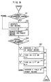
- Fig. 9 shows a flow chart of processing procedure of the internal table configuration.
- Fig. 10 shows contents of the table configuration of Fig. 8 during the operation.
- Fig. 4 shows the block configuration of entire system whereto the present invention is applied.
- An arithmetic unit 31, a memory unit 32, a CRT display unit 33, and a keyboard input unit 34 are connected via a bus 35.
- Fig. 5 shows the configuration of software of this embodiment stored in the memory unit 32.
- a control section 41, an input/output section 42, an inference section 43, a debugger display section 44, a user program section 46 and an execution management stack section 47 are included in the software configuration.
- the control section 41 is at first activated by a system start signal 45.
- the control section 41 analyzes a command 411 supplied from the keyboard input unit 34 by the user and issues either a signal 451 for activating the input/output section 42 or a signal 452 for activating the inference section 43.
- the input/output section 42 stores a program 421 supplied by the user into the user program section 46.
- the inference section 43 refers to the user program section 46, and produces a solution to a question supplied by the user while using the execution management stack section 47.
- the debugger display section 44 successively supervises the progress of processing conducted in the inference section 43 and sends the supervision result 442 to the user.
- the operation of the debugger display section 44 will now be described by referring to Fig. 6.
- the debugger display section 44 includes a trace display section 49, an operation range grasp section 50, an operation situation supervision stack 51, an operation range table 52, and an operation range display section 53.
- the inference section 43 produces a starting signal 491 for the trace display section 49 and the operation range grasp section 50 at the time when the program passes through the control point in the "clause model".
- the inference section sends out to the trace display section 49 and the operation range grasp section 50 a signal 492 relating to a class 71 of a control point shown in Fig. 7, a procedure name 72 during execution, a consistent call number 73 generated whenever a procedure call is produced, and a call level 74 for indicating the next level of the call.
- the trace display section 49 traces the signal 492 to successively send out the trace display result 61.
- Fig. 7 shows output examples of trace displays resulting from applying the operation shown in Fig.
- the operation range grasp section 50 grasps operation status of each procedure, each head term, and each body term having been executed, and records them on the operation range table 52, as will be explained below with reference to Fig. 8A and 9.
- the inference section 43 sends out a start signal 531 to start the operation range display section 53.
- the operation range display section 53 displays the operation ranges of each procedure, each head term and each body term on a display 62 by making thick only sides which have actually been activated among upper, right, left and lower sides of box-shaped figures surrounding each procedure, each head term, and each body term.
- Fig. 3 shows a display example of operation range for the procedure d-letter (X) derived after the operation shown in Fig. 2.
- the head term of first clause 1 has been activated twice which has resulted in no successful end. So, only the left side 24A of the box-shaped figure designated by 24 surrounding the term has beem marked thick.
- the head term of second clause 2 of d _ letter procedure has been activated twice which has resulted in a successful end and an unsuccessful end. So, the upper side 26B and left side 26A of the box-shaped figure designated by 26 surrounding the term have been marked thick.
- the head term 3A and body trem 3B of third clause 3 have been activated which has resulted in a successful end. So, the upper sides 28B and 30B of box-shaped figures designated by 28 and 30 surrounding the head term 3A and the body term 3B respectively don been marked thick. Examples of the configuration of the operation situation supervision stack 51 and the operation range table 52 which are deeply related to the present invention will now be described together with details of the processing algorithm of the operation range grasp section 50.
- Fig. 8A shows the detailed structure of the operation situation supervision stack 51.
- Fig. 8B shows the detailed structure of the operation range table 52.
- the operation situation supervision stack 51 stores therein a record 77 composed of six kinds of information.
- the six kinds of information are a call procedure name 72, a consistent call number 73, a control point class 71 distinguishing between call (hereafter referred to as C), exit (successful end, hereafter referred to as E), redo (recall, hereafter referred to as R), and fail (unsuccessful end, hereafter referred to as F), a call level 74, a current clause number 75 (hereafter referred to as L number) representing the number of clause now under execution, and a current term number 76 (hereafter referred to as C number) representing the number of term now under execution.
- L number current clause number
- C number current term number
- the operation range table 52 is composed of a collection of records 80.
- the record 80 is composed of the procedure name 72 and an arrangement 79 of four kinds of operation flags (C-E, C-F, R-E and R-F flags) for each term (head term and body term) of each clause included in that procedure.
- Each of the C-E, C-F, R-E and R-F flags is a 1-bit flag when a form in a procedure is executed to assume one of the four operation statuses i.e. C-E, C-F, R-E, and R-F operation statuses, the corresponding flag is set to "1" and the other three flags set to "0".
- the operation range grasp section 50 is activated by the inference section 43 when the control point in the "clause model" of the program is passed through. Then the section 50 performs the processing as follows.
- Step 91 Determine the control point class 71 of the information 492 supplied from the inference section 43 (hereafter referred to as current information). Proceed to step 92 if the class is C (call), otherwise proceed to step 93.
- Step 92 Store the current information into the operation situation supervision stack 51. Set both the L number and C number to 1 and proceed to step 93.
- Step 93 Search the operation situation supervision stack 51 for the record 77 having the same number as the consistent call number 73 of the current information.
- This record is hereafter referred to as current record.
- This record is referred to as parent record.
- Step 94 Determine the control point class 71 of the current information. If the class is "R”, proceed to step 95. If the class is "E”, proceed to step 96. If the class is "F”, proceed to step 97. Otherwise, proceed to step 98.
- Step 95 The control point class of the current record is defined to be "R", and the C number of the parent record is decreased by 1. Thus the processing is completed.
- Step 96 Determine the control point class 71 of the current record. If the class is "C”, set the operation status flag C-E of the operation range table 52 corresponding to the procedure name, L number and C number of the parent record to "1". If the class is "R”, set the operation flag R-E to "1". And set the control point class of the current record to "E” to complete the processing. Step 97: Determine the control point class of the current record. If the class is "C”, set the operation flag C-F of the execution range table 52 corresponding to the procedure name, L number and C number of the parent record to "1". If the class is "R”, set the operation flag R-F to "1". If the result becomes zero, increase the L number by 1 and set the C number to 1. And delete the current record to finish the processing.
- Step 98 Increase the C number of the parent record by 1 and finish the processing.
- Figs. 10A and 10B respectively show the contents of the operation situation supervision stack 51 and the operation range table 52 when the operation range grasp section 50 has processed the first information to the eighth information shown in Fig. 7. Since the L number 75 and C number 76 of the first record of the operation situation supervision stack 51 are respectively 3 and 2, it is known that the call source of the second record is the second term of the third clause of the procedure d-letter.
- Fig. 11 shows another example of display of program execution range derived by the present embodiment.
- Procedure p shown in Figure 11 has three clauses, and thick sides of box-shaped figures surrounding terms included in these clauses indicate which operations have already been executed. For example, as the upper sides of box-shaped figures designated by 100 and 102 have not been marked thick, it is readily understood from this display that the first clause is not used, and as the right side of the box-shaped figure designated by 110 and the left side of the box-shaped figure designated by 112 have been marked thick, backtracking is incurred one or more times between s(X, Y) and r(A, Y) of the third clause. It is also understood that the recall for this predicate has not been effected, and the call for the predicate has not brought about an unsuccessful end.
- the display of the operation range agrees with the declarative understanding method of the program described by a logical language, i.e., the program understanding method based on the standpoint that each procedure and each clause represents identical facts. That is to say, identical facts which have been used are displayed. As a result, the efficiency in test and debugging work is improved.
Landscapes
- Engineering & Computer Science (AREA)
- Theoretical Computer Science (AREA)
- General Engineering & Computer Science (AREA)
- Physics & Mathematics (AREA)
- General Physics & Mathematics (AREA)
- Software Systems (AREA)
- Quality & Reliability (AREA)
- Computing Systems (AREA)
- Computer Hardware Design (AREA)
- Data Mining & Analysis (AREA)
- Human Computer Interaction (AREA)
- Debugging And Monitoring (AREA)
- Devices For Executing Special Programs (AREA)
Description
- The present invention relates to a test and debug support method for a logical language, and in particular to an operation range display method of program suitable to the test and debug based upon declarative program understanding.
- A program understanding method for debugging a logical language is discussed in a paper entitled "Understanding the Control Flow of PROLOG Programs" written by L. Byrd, D.A.I Research Paper 151,
pages 1 to 12 Dept. of Artifical Intelligence, Univ. of Edinburgh, in Proceeding of Logic Programming Workshop, Debrecen, Hungary, 1980. In this paper, an operation grasp model for each procedure taken as a unit is proposed, and the necessity of an operation grasp model for each clause taken as a unit is implied. The operation grasp model for clause taken as a unit corresponding to this implication is described in Prolog-KABA Reference Manual (1984),pages 49 to 61 published by Iwasaki Electronics Corporation in Japan, for example. Further, operation grasp models (referred to as "clause models") for each clause taken as a unit, for each head term of a clause taken as a unit, and for each body term of a clause taken as a unit are proposed in a paper entitled "Function and Effect of Logical Basic Processing system LONLI" presented by Hirose et al. at the 29th National Conference of the Information Processing Society of Japan (1984). - In any of these papers, however, the problem of display method of the operation mode on those operation grasp models is not recognized.
- As for the display method of the operation mode, a proposal relating to the visual display of the operation process of a logical language is made in a paper entitled "Diagrammatical Operation Display Method of Prolog" written by Goto, document 27-6, Working Group of Symbol Manipulation, Information Processing Society of Japan (1984). And a proposal relating to the display method of the operation grasp model for each clause taken as a unit is made by Numao et al. in a paper entitled "PROEDIT, a screen oriented prolog programming environment", proceedings of the logic programming conference ′85 in Japan (1985).
- In any of the above described papers, however, support to declarative program undestanding of the program described with a logical language is not considered.
- The publication "Proceedings of the ACM Sigplan '85: Symposium On Language Issues In Programming Enviroments", vol. 20, no. 7, page 179, 190 by Francez et.al. discloses a debug support method for a logical language, and in particular an operation range display method for a program suitable for debugging based upon declarative program understanding, said method effecting highlighting of active procedures during program execution. Such a display does not consider the history of the program execution on a term by term basis and is therefore only of limited use in debugging.
- In testing and debugging a program, it is necessary to understand whether the program operates as intended or not. For supporting this understanding, it is desirable that the information supplied by a language processing system matches to the program understanding method of the programmer.
- As methods for understanding the operation of the program in case of a logical language, there are two methods, i.e., procedural understanding method and declarative understanding method. It can be said that the procedural understanding method provides more minute operation understanding than the declarative understanding. However, the programmer does not always produce a program by using only this minute understanding method.
- For example, an example of programming using "d-letter (A) the logical language PROLOG as shown in Fig. 1 is assumed. A PROLOG program comprises one or plural procedures, and each procedure comprises one or plural clauses. A clause comprises a sequence of one or plural terms and the first term of the sequence is called a head term and others are called body terms. The program shown in Fig. 1 comprises one procedure "d_letter" and it has three clauses as designated by
numerals Clauses head term 3A and onebody term 3B. This program determines whether a list includes two consecutive identical elements or two alternate identical elements. This program is more easily understood by using the declarative understanding method described below. A number of programmers produce programs on the basis of this understanding method. - (Clause 1) ...
- If the argument A is a list, and the first and second elements in the list are the same X, d-letter (A) holds true.
- (Clause 2) ...
- If the argument A is a list, and the first and third elements in the list are the same X, d-letter (A) holds true.
- (Clause 3) ...
- If the argument A is a list, and d-letter (L) holds true on the second and the next following lists, d-letter (A) holds true.
- It is now assumed that a call
? - d * letter ([a, b, c, b]). is issued to the above described program. In the prior art, the program operation attendant upon this call is represented by the display of the operation path. Fig. 2 shows an example of display of the operation path when the "clause" model is used. Arrows in Fig. 2 faithfully show the processing procedure of the processing system of the logical language prolog. - When the above program call is issued,
clause 1 in d _ letter procedure is executed which results in an unsuccessful end,clause 2 in d _ letter procedure is executed which also results in an unsuccessful end, and the head term of clause 3 is executed which results in a successful end, so the next term, i.e., the body term of clause 3 is executed, and d _ letter procedure is called recursively. The sequence of the above-explained operations are indicated by the arrow passing through the box-shaped figures designated 8, 10, 12 and 14. After the second call of the d_ letter procedure,clauses clause 2 results in a successful end. These operations are indicated by the arrow passing through the box-shaped figure designated by 16 and 18. That is to say, the arrows are displays corresponding to the procedural understanding method. It is difficult to make these displays correspond to understanding of the above described (clause 1), (clause 2) and (clause 3), i.e., the declarative understanding method. Because the displayed entire operation path extending from the program start to the program end must be tracked for reading out of the display of Fig. 2 the necessary information representing which clause has been used. - An object of the present invention is to provide a program operation range display method suitable to the test and debugging work based upon the declarative program understanding of the program described by the logical language.
- The present invention as claimed in
claim 1 is based upon the fact that the principal information used in the declarative understanding method is the cumulative information obtained by overlapping the operation paths extending from the program start to the program end for each procedure, each head term and each body term. In accordance with the present invention, therefore, the operation range is displayed for each procedure, each head term and each body term. Fig. 3 shows an example of display according to the present invention when the execution shown in Fig. 2 has been conducted. The displays are associated with four sides of box-shaped figures surrounding respective terms and are easy for programmers knowing the conventional operation path display (Fig. 2) to learn. - Fig. 1 shows an example of program described by using the logical language.
- Fig. 2 shows an example of execution trace using the "clause" model.
- Figs. 3 and 11 show examples of operation range displays according to a method of the present invention.
- Figs. 4 to 6 show the hardware configuration of embodiments according to the present invention.
- Fig. 7 shows an example of the trace display output.
- Fig. 8 shows the configuration of an internal table for producing display data of the present invention.
- Fig. 9 shows a flow chart of processing procedure of the internal table configuration.
- Fig. 10 shows contents of the table configuration of Fig. 8 during the operation.
- Fig. 4 shows the block configuration of entire system whereto the present invention is applied. An
arithmetic unit 31, amemory unit 32, aCRT display unit 33, and akeyboard input unit 34 are connected via abus 35. - Fig. 5 shows the configuration of software of this embodiment stored in the
memory unit 32. Acontrol section 41, an input/output section 42, aninference section 43, adebugger display section 44, auser program section 46 and an executionmanagement stack section 47 are included in the software configuration. - The operation of the whole system will now be described. In Fig. 5, arrows of broken lines represent flow of control signals, and arrows of solid lines represent flow of data signals. The
control section 41 is at first activated by asystem start signal 45. Thecontrol section 41 analyzes acommand 411 supplied from thekeyboard input unit 34 by the user and issues either asignal 451 for activating the input/output section 42 or asignal 452 for activating theinference section 43. The input/output section 42 stores aprogram 421 supplied by the user into theuser program section 46. Theinference section 43 refers to theuser program section 46, and produces a solution to a question supplied by the user while using the executionmanagement stack section 47. Thedebugger display section 44 successively supervises the progress of processing conducted in theinference section 43 and sends thesupervision result 442 to the user. The operation of thedebugger display section 44 will now be described by referring to Fig. 6. - The
debugger display section 44 includes atrace display section 49, an operation range grasp section 50, an operationsituation supervision stack 51, an operation range table 52, and an operationrange display section 53. - During the execution of the program, the
inference section 43 produces a startingsignal 491 for thetrace display section 49 and the operation range grasp section 50 at the time when the program passes through the control point in the "clause model". At the same time, the inference section sends out to thetrace display section 49 and the operation range grasp section 50 a signal 492 relating to aclass 71 of a control point shown in Fig. 7, aprocedure name 72 during execution, aconsistent call number 73 generated whenever a procedure call is produced, and acall level 74 for indicating the next level of the call. Thetrace display section 49 traces the signal 492 to successively send out thetrace display result 61. Fig. 7 shows output examples of trace displays resulting from applying the operation shown in Fig. 2 to the program of Fig. 1. By using the operationsituation supervision stack 51 on the basis of the above described signal 492 supplied from theinference section 43, the operation range grasp section 50 grasps operation status of each procedure, each head term, and each body term having been executed, and records them on the operation range table 52, as will be explained below with reference to Fig. 8A and 9. - When the operation range display indication program is executed independent of the above described control point transit timing, the
inference section 43 sends out astart signal 531 to start the operationrange display section 53. On the basis of the information recorded in the operation range table 52, the operationrange display section 53 displays the operation ranges of each procedure, each head term and each body term on adisplay 62 by making thick only sides which have actually been activated among upper, right, left and lower sides of box-shaped figures surrounding each procedure, each head term, and each body term. Fig. 3 shows a display example of operation range for the procedure d-letter (X) derived after the operation shown in Fig. 2. - The head term of
first clause 1 has been activated twice which has resulted in no successful end. So, only theleft side 24A of the box-shaped figure designated by 24 surrounding the term has beem marked thick. The head term ofsecond clause 2 of d _ letter procedure has been activated twice which has resulted in a successful end and an unsuccessful end. So, theupper side 26B and leftside 26A of the box-shaped figure designated by 26 surrounding the term have been marked thick. Thehead term 3A andbody trem 3B of third clause 3 have been activated which has resulted in a successful end. So, theupper sides 28B and 30B of box-shaped figures designated by 28 and 30 surrounding thehead term 3A and thebody term 3B respectively habe been marked thick. Examples of the configuration of the operationsituation supervision stack 51 and the operation range table 52 which are deeply related to the present invention will now be described together with details of the processing algorithm of the operation range grasp section 50. - Fig. 8A shows the detailed structure of the operation
situation supervision stack 51. Fig. 8B shows the detailed structure of the operation range table 52. - Whenever a new procedure call occurs, the operation
situation supervision stack 51 stores therein arecord 77 composed of six kinds of information. The six kinds of information are acall procedure name 72, aconsistent call number 73, acontrol point class 71 distinguishing between call (hereafter referred to as C), exit (successful end, hereafter referred to as E), redo (recall, hereafter referred to as R), and fail (unsuccessful end, hereafter referred to as F), acall level 74, a current clause number 75 (hereafter referred to as L number) representing the number of clause now under execution, and a current term number 76 (hereafter referred to as C number) representing the number of term now under execution. - The operation range table 52 is composed of a collection of
records 80. Therecord 80 is composed of theprocedure name 72 and anarrangement 79 of four kinds of operation flags (C-E, C-F, R-E and R-F flags) for each term (head term and body term) of each clause included in that procedure. Each of the C-E, C-F, R-E and R-F flags is a 1-bit flag when a form in a procedure is executed to assume one of the four operation statuses i.e. C-E, C-F, R-E, and R-F operation statuses, the corresponding flag is set to "1" and the other three flags set to "0". - The processing algorithm of the operation range grasp section 50 will now be described by referring to Fig. 9.
- During execution of the program, the operation range grasp section 50 is activated by the
inference section 43 when the control point in the "clause model" of the program is passed through. Then the section 50 performs the processing as follows. - Step 91: Determine the
control point class 71 of the information 492 supplied from the inference section 43 (hereafter referred to as current information). Proceed to step 92 if the class is C (call), otherwise proceed to step 93. - Step 92: Store the current information into the operation
situation supervision stack 51. Set both the L number and C number to 1 and proceed to step 93. - Step 93: Search the operation
situation supervision stack 51 for therecord 77 having the same number as theconsistent call number 73 of the current information. This record is hereafter referred to as current record. Search the operationsituation supervision stack 51 from the current record into the lower rank direction (into the direction of older record storage) successively for a record having a call depth less than that of the current record by one. This record is referred to as parent record. - Step 94: Determine the
control point class 71 of the current information. If the class is "R", proceed to step 95. If the class is "E", proceed to step 96. If the class is "F", proceed to step 97. Otherwise, proceed to step 98. - Step 95: The control point class of the current record is defined to be "R", and the C number of the parent record is decreased by 1. Thus the processing is completed.
- Step 96: Determine the
control point class 71 of the current record. If the class is "C", set the operation status flag C-E of the operation range table 52 corresponding to the procedure name, L number and C number of the parent record to "1". If the class is "R", set the operation flag R-E to "1". And set the control point class of the current record to "E" to complete the processing. Step 97: Determine the control point class of the current record. If the class is "C", set the operation flag C-F of the execution range table 52 corresponding to the procedure name, L number and C number of the parent record to "1". If the class is "R", set the operation flag R-F to "1". If the result becomes zero, increase the L number by 1 and set the C number to 1. And delete the current record to finish the processing. - Step 98: Increase the C number of the parent record by 1 and finish the processing.
- Figs. 10A and 10B respectively show the contents of the operation
situation supervision stack 51 and the operation range table 52 when the operation range grasp section 50 has processed the first information to the eighth information shown in Fig. 7. Since theL number 75 andC number 76 of the first record of the operationsituation supervision stack 51 are respectively 3 and 2, it is known that the call source of the second record is the second term of the third clause of the procedure d-letter. - Fig. 11 shows another example of display of program execution range derived by the present embodiment.
- Procedure p shown in Figure 11 has three clauses, and thick sides of box-shaped figures surrounding terms included in these clauses indicate which operations have already been executed. For example, as the upper sides of box-shaped figures designated by 100 and 102 have not been marked thick, it is readily understood from this display that the first clause is not used, and as the right side of the box-shaped figure designated by 110 and the left side of the box-shaped figure designated by 112 have been marked thick, backtracking is incurred one or more times between s(X, Y) and r(A, Y) of the third clause. It is also understood that the recall for this predicate has not been effected, and the call for the predicate has not brought about an unsuccessful end.
- In accordance with the present invention, the display of the operation range agrees with the declarative understanding method of the program described by a logical language, i.e., the program understanding method based on the standpoint that each procedure and each clause represents identical facts. That is to say, identical facts which have been used are displayed. As a result, the efficiency in test and debugging work is improved.
Claims (4)
- An operation range display method for a system which executes a logical language program which comprises one or plural procedures, each procedure comprising one or plural clauses, each clause comprising one or plural terms, comprising the steps of:
by an operation grasp section (50),- a) grasping, in response to execution of each of the terms included in the program, an operation status of the term including a call procedure name (72), a consistent call number (73), a control point class (71) distinguishing between either a call (C), a successful end (E), a recall (R), or an unsuccessful and (F), a call level (74), a current clause number (75) representing the number of clause under execution, and a current term number (76) representing the number of term under execution;- b) storing in an operation supervision stack (51) records (77) of said operation status of each term;- c) setting, on the basis of the information in said record (77), operation flags for indicating which operation has already been conducted for each term among four kinds of operation, i.e., call-successful end (C-E), call unsuccessful end (C-F), recall successful end (R-E), and recall unsuccessful end (R-F);- d) storing said operation flags (79) in an operation range table (52); and
by an operation display section (53),- e) displaying the operation range of each term on a display (62) based on the status of said operation flags by associating said four kinds of operation to respective sides of a box shaped figure surrounding each term, respectively, the displaying of each said figure depending upon the respective status operation flags at a given time of execution of the respective term. - The method of claim 1, wherein said figure is a rectangle.
- The method of claim 2, wherein each side of said rectangle is displayed in a manner different from a normal display state, when a respective operation flag associated to a respective side has been set for the corresponding term.
- The method of claim 3, wherein said different manner of displaying consists in using a thicker line for the respective sides of said rectangle associated to the respective operation flags which are set than for the other sides of said rectangle.
Applications Claiming Priority (2)
| Application Number | Priority Date | Filing Date | Title |
|---|---|---|---|
| JP60195848A JPH079628B2 (en) | 1985-09-06 | 1985-09-06 | How to display operating range of logic language |
| JP195848/85 | 1985-09-06 |
Publications (3)
| Publication Number | Publication Date |
|---|---|
| EP0213486A2 EP0213486A2 (en) | 1987-03-11 |
| EP0213486A3 EP0213486A3 (en) | 1989-05-10 |
| EP0213486B1 true EP0213486B1 (en) | 1995-06-21 |
Family
ID=16348014
Family Applications (1)
| Application Number | Title | Priority Date | Filing Date |
|---|---|---|---|
| EP86111186A Expired - Lifetime EP0213486B1 (en) | 1985-09-06 | 1986-08-12 | Method for displaying operation range of logical language |
Country Status (4)
| Country | Link |
|---|---|
| US (1) | US4794529A (en) |
| EP (1) | EP0213486B1 (en) |
| JP (1) | JPH079628B2 (en) |
| DE (1) | DE3650337T2 (en) |
Families Citing this family (3)
| Publication number | Priority date | Publication date | Assignee | Title |
|---|---|---|---|---|
| JP2696210B2 (en) * | 1987-03-20 | 1998-01-14 | 株式会社日立製作所 | Displaying execution trace of logical language program |
| US4943968A (en) * | 1987-03-04 | 1990-07-24 | Hitachi, Ltd. | Method of displaying execution trace in a logic programming language processing system |
| DE4323787A1 (en) * | 1993-07-15 | 1995-01-19 | Siemens Ag | Procedure for testing an object-oriented program |
Family Cites Families (1)
| Publication number | Priority date | Publication date | Assignee | Title |
|---|---|---|---|---|
| US4481602A (en) * | 1981-04-06 | 1984-11-06 | International Business Machines Corporation | Font compression and decompression for character generation |
-
1985
- 1985-09-06 JP JP60195848A patent/JPH079628B2/en not_active Expired - Lifetime
-
1986
- 1986-08-12 EP EP86111186A patent/EP0213486B1/en not_active Expired - Lifetime
- 1986-08-12 DE DE3650337T patent/DE3650337T2/en not_active Expired - Fee Related
- 1986-08-13 US US06/895,954 patent/US4794529A/en not_active Expired - Fee Related
Also Published As
| Publication number | Publication date |
|---|---|
| JPH079628B2 (en) | 1995-02-01 |
| JPS6257033A (en) | 1987-03-12 |
| EP0213486A3 (en) | 1989-05-10 |
| DE3650337T2 (en) | 1996-03-07 |
| US4794529A (en) | 1988-12-27 |
| DE3650337D1 (en) | 1995-07-27 |
| EP0213486A2 (en) | 1987-03-11 |
Similar Documents
| Publication | Publication Date | Title |
|---|---|---|
| US6016474A (en) | Tool and method for diagnosing and correcting errors in a computer program | |
| Cook et al. | Space lower bounds for maze threadability on restricted machines | |
| US5412756A (en) | Artificial intelligence software shell for plant operation simulation | |
| EP0331060B2 (en) | Programmable controller with stored tokenized source code | |
| US4730315A (en) | Diagrammatic method of testing program | |
| CA2107833C (en) | Regeneration of process control flow diagrams for programmable logic controllers | |
| Robinson et al. | Formalizing a hierarchical structure of practical mathematical reasoning | |
| Frenkel | Toward automating the software-development cycle | |
| JPH04337843A (en) | Program operation display method | |
| JPH05307096A (en) | Device for monitoring and controlling operation of facility and method for monitoring operation of facility | |
| JPS6116100B2 (en) | ||
| US4794529A (en) | Method for displaying operation range of logical language | |
| WO1995032476A1 (en) | A system and method for creating design configurations and for controlling the execution of multiple design tools | |
| EP0210742A2 (en) | Method for controlling computer program execution sequences | |
| JPH02275539A (en) | Debugging system | |
| Cox et al. | Advanced programming aids in PROGRAPH | |
| JP2579996B2 (en) | Core state prediction device | |
| Yin | An integrated software design paradigm | |
| JPS6074088A (en) | Extraction processing system for hidden-surface removed graphic | |
| Schafer | Graphical interactions with an automatic programming system | |
| JPS63140335A (en) | Automatic procedure generating and processing system | |
| JPH01177137A (en) | Computer execution diagnostic device | |
| JPH05265776A (en) | Method for visualizing parallel execution process | |
| JPH01288930A (en) | Discrete event type simulation system | |
| WO2004097545A2 (en) | A method of executing a computer program |
Legal Events
| Date | Code | Title | Description |
|---|---|---|---|
| PUAI | Public reference made under article 153(3) epc to a published international application that has entered the european phase |
Free format text: ORIGINAL CODE: 0009012 |
|
| AK | Designated contracting states |
Kind code of ref document: A2 Designated state(s): DE FR GB |
|
| PUAL | Search report despatched |
Free format text: ORIGINAL CODE: 0009013 |
|
| AK | Designated contracting states |
Kind code of ref document: A3 Designated state(s): DE FR GB |
|
| 17P | Request for examination filed |
Effective date: 19891027 |
|
| 17Q | First examination report despatched |
Effective date: 19920205 |
|
| GRAA | (expected) grant |
Free format text: ORIGINAL CODE: 0009210 |
|
| AK | Designated contracting states |
Kind code of ref document: B1 Designated state(s): DE FR GB |
|
| REF | Corresponds to: |
Ref document number: 3650337 Country of ref document: DE Date of ref document: 19950727 |
|
| ET | Fr: translation filed | ||
| PLBE | No opposition filed within time limit |
Free format text: ORIGINAL CODE: 0009261 |
|
| STAA | Information on the status of an ep patent application or granted ep patent |
Free format text: STATUS: NO OPPOSITION FILED WITHIN TIME LIMIT |
|
| 26N | No opposition filed | ||
| PGFP | Annual fee paid to national office [announced via postgrant information from national office to epo] |
Ref country code: FR Payment date: 19980616 Year of fee payment: 13 |
|
| PGFP | Annual fee paid to national office [announced via postgrant information from national office to epo] |
Ref country code: GB Payment date: 19980731 Year of fee payment: 13 |
|
| PGFP | Annual fee paid to national office [announced via postgrant information from national office to epo] |
Ref country code: DE Payment date: 19981027 Year of fee payment: 13 |
|
| PG25 | Lapsed in a contracting state [announced via postgrant information from national office to epo] |
Ref country code: GB Free format text: LAPSE BECAUSE OF NON-PAYMENT OF DUE FEES Effective date: 19990812 |
|
| GBPC | Gb: european patent ceased through non-payment of renewal fee |
Effective date: 19990812 |
|
| PG25 | Lapsed in a contracting state [announced via postgrant information from national office to epo] |
Ref country code: FR Free format text: LAPSE BECAUSE OF NON-PAYMENT OF DUE FEES Effective date: 20000428 |
|
| PG25 | Lapsed in a contracting state [announced via postgrant information from national office to epo] |
Ref country code: DE Free format text: LAPSE BECAUSE OF NON-PAYMENT OF DUE FEES Effective date: 20000601 |
|
| REG | Reference to a national code |
Ref country code: FR Ref legal event code: ST |