EP0213199B1 - Apparatus and method for transporting a spacecraft and a fluid propellant from the earth to a substantially low gravity environment above the earth - Google Patents
Apparatus and method for transporting a spacecraft and a fluid propellant from the earth to a substantially low gravity environment above the earth Download PDFInfo
- Publication number
- EP0213199B1 EP0213199B1 EP86902089A EP86902089A EP0213199B1 EP 0213199 B1 EP0213199 B1 EP 0213199B1 EP 86902089 A EP86902089 A EP 86902089A EP 86902089 A EP86902089 A EP 86902089A EP 0213199 B1 EP0213199 B1 EP 0213199B1
- Authority
- EP
- European Patent Office
- Prior art keywords
- spacecraft
- earth
- fluid propellant
- propellant
- low gravity
- Prior art date
- Legal status (The legal status is an assumption and is not a legal conclusion. Google has not performed a legal analysis and makes no representation as to the accuracy of the status listed.)
- Expired
Links
- 239000012530 fluid Substances 0.000 title claims abstract description 109
- 239000003380 propellant Substances 0.000 title claims abstract description 103
- 230000005484 gravity Effects 0.000 title claims abstract description 48
- 238000000034 method Methods 0.000 title claims description 11
- 239000000446 fuel Substances 0.000 claims description 4
- 239000007800 oxidant agent Substances 0.000 claims description 4
- 239000007789 gas Substances 0.000 description 9
- 230000001133 acceleration Effects 0.000 description 2
- 239000001307 helium Substances 0.000 description 2
- 229910052734 helium Inorganic materials 0.000 description 2
- SWQJXJOGLNCZEY-UHFFFAOYSA-N helium atom Chemical compound [He] SWQJXJOGLNCZEY-UHFFFAOYSA-N 0.000 description 2
- 230000009467 reduction Effects 0.000 description 2
- 230000000295 complement effect Effects 0.000 description 1
- 230000008602 contraction Effects 0.000 description 1
- 238000007599 discharging Methods 0.000 description 1
- 229920001971 elastomer Polymers 0.000 description 1
- 239000000806 elastomer Substances 0.000 description 1
- 231100001261 hazardous Toxicity 0.000 description 1
- 238000010348 incorporation Methods 0.000 description 1
- 239000007788 liquid Substances 0.000 description 1
- 238000012986 modification Methods 0.000 description 1
- 230000004048 modification Effects 0.000 description 1
- 230000003287 optical effect Effects 0.000 description 1
- 230000008569 process Effects 0.000 description 1
- 230000000284 resting effect Effects 0.000 description 1
- 238000009987 spinning Methods 0.000 description 1
Images


Classifications
-
- B—PERFORMING OPERATIONS; TRANSPORTING
- B64—AIRCRAFT; AVIATION; COSMONAUTICS
- B64G—COSMONAUTICS; VEHICLES OR EQUIPMENT THEREFOR
- B64G1/00—Cosmonautic vehicles
- B64G1/14—Space shuttles
Definitions
- the invention relates generally to the transport of spacecraft from the earth to the relatively low gravity environment above the earth and more particularly to the transport of spacecraft and fluid propellant.
- a fundamental objective in designing and building spacecraft is to minimize the overall mass of the spacecraft. This is in part because the mass of the spacecraft is a significant factor in determining what proportion of a spacecraft cargo carried aloft should comprise propellant for manuevering the spacecraft once it has entered the relatively low gravity environment above the earth and what proportion may comprise electronic, optical or other systems.
- the propellant may comprise approximately 75 % of the combined weight of the spacecraft and the propellant.
- a fluid propellant powered spacecraft launched from the space shuttle for geosynchronous orbit about the earth ordinarily requires enough.
- fluid propellant In earlier spacecraft launches, fluid propellant usually was carried aloft within containers supported by support structure integral to the spacecraft.
- the rapid acceleration and vibration of the fluid propellant often resulted in loading of the propellant with forces equal to many times the force that the earth's gravity would exert on the propellant if it were at rest on the surface of the earth. Consequently, containers containing the propellant and support structure supporting it had to be sturdy enough to withstand such high loading.
- sturdier containers and support structure generally were more massive. Thus, the containers and support structure of earlier spacecraft had to be massive and sturdy enough to withstand the high loading of the propellant during the launch.
- the present invention provides an apparatus for transporting a spacecraft and spacecraft fluid propellant from the earth to a substantially low gravity environment above the earth, comprising :
- the invention also provides an apparatus for transporting a spacecraft and a spacecraft fluid propellant in accordance with the features of claim 10.
- the present invention also provides a method for transporting a spacecraft and spacecraft fluid propellant from the earth to a substantially low gravity environment above the earth, said method comprising the steps of :
- the apparatus and method of the present invention permit the use of a spacecraft comprising reduced support structure mass. This is because the spacecraft support structure need not support the fluid propellant during launch from earth when accelerational, gravitational and vibrational forces may be exerted upon the propellant. Thus, a spacecraft is possible which, due to reduced support structure mass, more efficiently uses fluid propellant and which, therefore, may obviate the need for staging certain spacecraft components.
- the present invention provides a novel apparatus and method for transporting a spacecraft and fluid propellant from the earth to a relatively low gravity environment above the earth with substantially reduced loading of the spacecraft due to accelerational, gravitational, vibrational or other forces upon the fluid propellant during the transport.
- the apparatus comprises first, second, third and fourth tanks, 20, 22, 24 and 26, respectively, external to a spacecraft 28, for containing a fluid bipropellant for use by the spacecraft 28, and first, second, third and fourth spacecraft tanks, 30, 32, 34 and 36, respectively, supported by spacecraft support structure 38 in a manner which will be understood by those possessing skill in the art, for receiving the fluid bipropellant from the respective external tanks, 20, 22, 24 and 26.
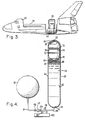
- the spacecraft 28 and the external tanks are disposed within the cargo bay 40 of a space shuttle 42 as shown in Fig. 3.
- the spacecraft 28 is secured within a generally U-shaped cradle 44 within the cargo bay .40, and the four external tanks, 20, 22, 24 and 26, are secured integral to the cradle 44 during the launch of the spacecraft 28 and the fluid bipropellant from the earth to the relatively low gravity environment above the earth.
- the four external tanks 20, 22, 24 and 26 are substantially identical as are the four spacecraft tanks 30, 32, 34 and 36.
- the exemplary drawings of the first external tank 20 and the first spacecraft tank 30 in Figs. 4 and 5 are representative of the remaining external and spacecraft tanks.
- the first external tank 20 comprises a generally elongated cylindrical central section 48 and first and second longitudinally spaced substantially hemispherical end closures 43 and 50, respectively, for enclosing opposite ends of the central section 46.
- the external tanks, 20, 22, 24 and 26 are disposed about the U-shaped cradle 44 with their longitudinal axes aligned substantially parallel to one another and to the longitudinal axis of the U-shaped cradle 44.
- the external tanks, 20, 22, 24 and 26, are laterally disposed with respect to one another within the cradle 44 in a generally semi-annular arrangement about the cradle 44.
- First and second external tanks, 20 and 22, respectively are disposed adjacent to one another near the base of the U-shaped cradle, and third and fourth external tanks 24 and 26, respectively, are disposed with the first and second tanks 20 and 22, respectively, located substantially between them such that the first external tank 20 is between the second and third external tanks, 22 and 24, respectively, and the second external tank 22 is between the first and fourth external tanks 20 and 26, respectively.
- the first and second external tanks 20 and 22, respectively contain the lighter propellant component, a fuel
- the third and fourth external tanks 24 and 26, respectively contain an oxidizer.
- the four spacecraft tanks, 30, 32, 34 and 36, supported by spacecraft support structure 38 each have a substantially spherical shape and are disposed about a central axis of the spacecraft; such that the centers of the four spherical tanks lie in a common plane ; such that the center of each tank is separated by approximately 90°, relative to the spacecraft central axis, from the centers of the tanks adjacent to it ; and such that the center of each tank is substantially equidistant from the spacecraft central axis.
- First and second spacecraft tanks 30 and 32, respectively, are disposed with the spacecraft central axis between them, and third and fourth spacecraft tanks 34 and 36, respectively, also are disposed with the spacecraft central axis between them.
- the fuel is transferred from the respective first and second external tanks 20 and 24 to the respective first and second spacecraft tanks 30 and 32 and the oxidizer is transferred from the respective third and fourth external tanks 24 and 26 to the respective third and fourth spacecraft tanks 34 and .36 by means more fully described below.
- spacecraft support structure 38 (which forms no part of the present invention) used to support the spacecraft tanks, 30, 32, 34 and 36, need not support fluid bipropellant during launch from the earth to the relatively low gravity environment above the earth. This is because during that portion of the spacecraft mission, the fluid bipropellant is contained within the cradle-mounted external tanks, 20, 22, 24 and 26.
- the support structure 38 used to support the spacecraft tanks, 30, 32, 34 and 36, and the fluid bipropellant transferred to those tanks generally need only be sturdy enough to withstand the relatively low forces exerted upon the spacecraft tanks, 30, 32, 34 and 36, and the bipropellant therein in the relatively low gravity environment above the earth such as acceleration loads generated by the spacecraft liquid propulsion motor 37. This can permit a reduction in the amount of spacecraft mass dedicated to support structure used to support the fluid bipropellant and a reduction in spacecraft complexity by obviating the need for the staging of certain spacecraft components.
- placing cylindrical external tanks, 20, 22, 24 and 26, about the U-shaped cradle 44 in the manner described makes efficient use of the limited space within the cargo bay 40, and that placing the spacecraft tanks, 30, 32, 34 and 36 about the central axis of the spacecraft 28 in the manner described helps to ensure that the spacecraft tanks, 30, 32, 34 and 36, and the fluid bipropellant transferred to those tanks are disposed about the spacecraft 28 in a balanced fashion such that the spacecraft 28 can rotate efficiently about its central axis after departing from the space shuttle 42.
- the first external tank 20 as illustrated in Figs. 4 and 5 substantially encloses a piston 54 slideably mounted therein to move substantially parallel to the longitudinal axis of the first external tank 20.
- the piston 54 comprises a cylindrical central section 56 and first and second substantially hemispherical. piston end closures 58 and 60, respectively, for enclosing opposite ends of the central section 56.
- the central section 56 of the piston 54 is diametrically sized to fit in snug slideable relation with interior walls 62 of an elongated cylindrical external tank central section 46 and is longitudinally sized to be significantly shorter than the central section 46 of the first external tank 20.
- the first and second substantially hemispherical piston end closures 58 and 60, respectively, are diametrically sized to be complementary to the respective first and second hemispherical external tank end closures 48 and 50, respectively, such that, when the piston 54 is in a first position, illustrated in Fig. 4, the first piston end closure 58 overlays a concave interior of the first external tank end closure 48, and when the piston 54 is in a second position, illustrated in Fig. 5, the convex second piston end closure 60 overlays a concave interior of the second external tank end closure 50.
- the piston comprises a guide 70 such as a piston ring which cooperates with the interior walls 62 of the external tank central section 46 to permit substantially rattle-free movement of the piston 54 between the first and second positions.
- the piston also includes a sliding seal 72 such as a spring energized wiper which maintains the tight fit between the piston 54 and the interior walls 62 as the piston 54 moves between the first and second positions.
- the sliding seal 72 substantially prevents the flow of fluid bipropellant between the piston 54 and the interior walls 62.
- the piston 54 includes means for providing a tight seal between a region about the apex 74 of the second piston end closure 60 and the region about the nadir 76 of the concave interior of the second external tank end closure 50 when the piston 54 is in the second position.
- the means for providing a seal for example, can be an O-ring 78 formed from a propellant compatible elastomer which encircles the apex 74 of the second piston end closure 60.
- the piston 54 defines a chamber suitable for containing a pressurant gas such as helium.
- the first piston end closure 58 defines a first piston outlet port 82 from the chamber at an apex of the first piston end closure 58.
- the first piston outlet port 82 permits pressurant gas flow during propellant expulsion.
- the second piston end closure 60 defines a second piston outlet port 88 at the apex 74 of the second piston end closure 60.
- a first valve 90 is provided for closing the second piston outlet port 88 when the piston 54 is in the first position and for openning the second piston outlet port 88 when the piston 54 is in the second position.
- the first valve 90 for example, can be a mechanically actuated relief valve.
- the second external tank end closure 60 defines an external tank outlet port 92 which opens into a first conduit defined by a first pipe 94 for carrying fluid between the external tank outlet port 92 and an inlet port 96 defined by the first spherical tank 30.
- a second conduit defined by a . second pipe 100 for carrying fluid branches from the first conduit.
- the second conduit opens into a residue container 102 defining a chamber for receiving residual fluid bipropellant from the first conduit.
- a fluid pressure sensor 106 is provided to monitor the fluid pressure within the first pipe 94.
- Second and third valves 108 and 109, respectively, are provided for opening and closing the first conduit, and a fourth valve 110 is provided for opening and and a fourth valve 110 is provided for opening and closing the second conduit.
- the second, third and fourth valves 108, 109 and 110, respectively, are responsive to the fluid pressure sensor 106 in a manner which will be understood by a person skilled in the art.
- a low spillage disconnect 112 is provided for disconnecting the first pipe 94 between the second and third valves 108 and 109. respectively, at a location between the third valve 109 and the external tank outlet port 92.
- the disconnect 112 for example, can be a quick disconnect type, actuated by force and released by pressure.
- the disconnect 112 is diagramatically shown in a connected configuration in Fig. 4 and in a disconnected configuration in Fig 5.
- each external tank, 20, 22, 24 and 26 contains a component 114 of the bipropellant, such as an oxidizer or a fuel.
- the piston 54 is in the first position and the bipropellant component 114 is interposed between the second piston end closure 60 and the second external tank end closure 50.
- the spacecraft tank 30 supported by the spacecraft support structure 38 is substantially evacuated.
- the piston 54 contains a pressurant gas such as helium. The pressure of the pressurant gas depends upon the particular needs of a launch, but a pressure of 6,89 bar (100 pounds per square inch) might be typical.
- the first, second, third and fourth valves, 90, 108, 109 and 110, respectively, are closed. Therefore, during the launch from the surface of the earth, the cradle 44 supports the external tank 20 and the bipropellant component 114 therein.
- the bipropellant is transferred from the external tanks, 20, 22, 24 and 26, to the spacecraft tanks, 30, 32, 34 and 36.
- the transfer involves the step of opening the second and third valves, 108 and 109, respectively.
- the pressurant gas begins exiting through the first piston outlet port 82 and filling a region between the first piston end closure 58 and the first external tank end closure 48, driving the piston 54 from the first position, illustrated in Fig. 4, to the second position, illustrated in Fig. 5, and forcing the bipropellant component 114 through the external tank outlet port 92 through the first pipe 94 and through the inlet port 96 defined by the spacecraft tank 30.
- the pressure sensor 106 measures the fluid pressure within the first pipe 94 as the bipropellant component 114 flows through the first pipe 94.
- the first valve 90 opens permitting pressurant gas to flow through the external tank outlet port 92 and into the first pipe 94.
- the pressure sensor 106 senses the drop of fluid flow as indicated by a drop of pressure in the first pipe 94 and causes the second and third valves 108 and 109, respectively, to close the first conduit and causes the fourth valve 110 to open the second conduit.
- the relatively high pressure gas substantially flushes residual fluid bipropellant 115 from the first conduit through second conduit and into the residue container 102.
- the first and fourth valves 90 and 110, respectively are closed by means which will be understood by those skilled in the art.
- first external tank 20 and first spacecraft tank 30 applies equally to the remaining external tanks, 22, 24 and 26, and spacecraft tanks, 32, 34 and 36.
- Each external tank, 20, 22, 24 and 26 has an associated spacecraft tank 30, 32, 34 and 36, respectively, to which it provides a bipropellant component.
- this one-to-one relation between external tanks and spacecraft tanks simplifies the process of accurately distributing the fluid bipropellant components to the spacecraft tanks 20, 22, 24 and 26. Accurate distribution is important since an improper balancing of the bipropellant mass about the central axis of the spacecraft 28 might prevent the spacecraft 28 from spinning properly about its cental axis.
- the apparatus and method of the present invention permit the use of a spacecraft 28 comprising fluid propellant support structure 38 suitable for supporting a fluid propellant in the relatively low gravity environment above the earth, but not necessarily as sturdy and massive as would be necessary to support the fluid propellant during the launch from actual surface of the earth. Therefore, a spacecraft 28 comprising reduced support structure mass can be provided. Such a spacecraft 28 might be less massive and, therefore, require less propellant for manuevering and might obviate the need for staging certain spacecraft components to reduce spacecraft mass.
- the apparatus and method of the present invention provide for fluid propellant transfer without significant spillage of the fluid propellant in the space shuttle cargo bay 40. This is an important factor because fluid propellant often can be hazardous to humans and to equipment.
- the number of external tanks need not be the same as the number of spacecraft tanks.
- the external tanks need not include a piston for discharging a propellant.
- a bladder comprising an outlet port which opens into the first conduit may be provided, and the pressurant gas introduced to the external tank might compress the bladder and force the propellant from the bladder and into a spacecraft tank.
- an external tank may include a bellows comprising an outlet port which opens into the first conduit, and contraction of the bellows might force the propellant from the bellows into a spacecraft tank.
Landscapes
- Engineering & Computer Science (AREA)
- Remote Sensing (AREA)
- Aviation & Aerospace Engineering (AREA)
- Filling Or Discharging Of Gas Storage Vessels (AREA)
Applications Claiming Priority (2)
| Application Number | Priority Date | Filing Date | Title |
|---|---|---|---|
| US707278 | 1985-03-01 | ||
| US06/707,278 US4699339A (en) | 1985-03-01 | 1985-03-01 | Apparatus and method for transporting a spacecraft and a fluid propellant from the earth to a substantially low gravity environment above the earth |
Publications (2)
| Publication Number | Publication Date |
|---|---|
| EP0213199A1 EP0213199A1 (en) | 1987-03-11 |
| EP0213199B1 true EP0213199B1 (en) | 1988-09-07 |
Family
ID=24841073
Family Applications (1)
| Application Number | Title | Priority Date | Filing Date |
|---|---|---|---|
| EP86902089A Expired EP0213199B1 (en) | 1985-03-01 | 1986-02-24 | Apparatus and method for transporting a spacecraft and a fluid propellant from the earth to a substantially low gravity environment above the earth |
Country Status (5)
| Country | Link |
|---|---|
| US (1) | US4699339A (enExample) |
| EP (1) | EP0213199B1 (enExample) |
| JP (1) | JPS62502187A (enExample) |
| DE (1) | DE3660664D1 (enExample) |
| WO (1) | WO1986005158A1 (enExample) |
Families Citing this family (12)
| Publication number | Priority date | Publication date | Assignee | Title |
|---|---|---|---|---|
| US4741502A (en) * | 1985-10-01 | 1988-05-03 | Hughes Aircraft Company | Method and apparatus for launching a spacecraft by use of a recoverable upper rocket stage |
| US4936528A (en) * | 1988-05-11 | 1990-06-26 | General Research Corporation | Method and apparatus for orbital debris mitigation |
| US6113032A (en) * | 1998-02-25 | 2000-09-05 | Kistler Aerospace Corporation | Delivering liquid propellant in a reusable booster stage |
| US7004185B2 (en) | 2001-08-17 | 2006-02-28 | Kistler Aerospace Corporation | Liquid loading techniques |
| US6845949B2 (en) * | 2002-07-23 | 2005-01-25 | The Boeing Company | System and methods for integrating a payload with a launch vehicle |
| US7114682B1 (en) * | 2004-02-18 | 2006-10-03 | Kistler Walter P | System and method for transportation and storage of cargo in space |
| US7118077B1 (en) * | 2005-03-11 | 2006-10-10 | Kistler Walter P | Platform and system for mass storage and transfer in space |
| US7156348B1 (en) | 2005-03-11 | 2007-01-02 | Kistler Walter P | Platform and system for propellant tank storage and transfer in space |
| US7559508B1 (en) | 2006-12-07 | 2009-07-14 | Taylor Thomas C | Propellant depot in space |
| JP5324478B2 (ja) * | 2007-03-09 | 2013-10-23 | マクドナルド デットウィラー アンド アソシエーツ インク. | 衛星燃料供給システムおよび方法 |
| FR2935686B1 (fr) * | 2008-09-08 | 2010-09-24 | Snecma | Fagot comportant deux paires de reservoirs et lanceur aeroporte comportant un tel fagot |
| US9475591B2 (en) * | 2013-11-19 | 2016-10-25 | Arthur Mckee Dula | Space launch apparatus |
Family Cites Families (10)
| Publication number | Priority date | Publication date | Assignee | Title |
|---|---|---|---|---|
| GB1114414A (en) * | 1964-06-18 | 1968-05-22 | British Aircraft Corp Ltd | Improvements in space vehicles |
| US3295791A (en) * | 1964-12-11 | 1967-01-03 | Dolphus H Black | Storage container mounting for space vehicles |
| US3923208A (en) * | 1974-07-19 | 1975-12-02 | Us Army | Fluid expulsion system having a tapered tank |
| US4032091A (en) * | 1976-03-05 | 1977-06-28 | Thomas J. Reddy, Trustee | Fuel line evacuation system |
| FR2569162A1 (fr) * | 1977-11-25 | 1986-02-21 | Ford Aerospace & Communication | Procede de mise sur orbite de satellites et de vaisseaux spatiaux |
| US4471926A (en) * | 1979-10-29 | 1984-09-18 | Trw Inc. | Transfer vehicle for use in conjunction with a reusable space shuttle |
| US4359201A (en) * | 1980-02-28 | 1982-11-16 | Hughes Aircraft Company | Payload deployment from shuttle with linear and angular velocity |
| FR2511970A1 (fr) * | 1981-09-02 | 1983-03-04 | Europ Agence Spatiale | Dispositif de ravitaillement en orbite pour satellites geostationnaires |
| WO1998031055A1 (en) * | 1997-01-09 | 1998-07-16 | Nichia Chemical Industries, Ltd. | Nitride semiconductor device |
| JP3369464B2 (ja) * | 1998-03-19 | 2003-01-20 | 日本電信電話株式会社 | 半導体装置 |
-
1985
- 1985-03-01 US US06/707,278 patent/US4699339A/en not_active Expired - Lifetime
-
1986
- 1986-02-24 JP JP61501661A patent/JPS62502187A/ja active Granted
- 1986-02-24 DE DE8686902089T patent/DE3660664D1/de not_active Expired
- 1986-02-24 EP EP86902089A patent/EP0213199B1/en not_active Expired
- 1986-02-24 WO PCT/US1986/000379 patent/WO1986005158A1/en not_active Ceased
Also Published As
| Publication number | Publication date |
|---|---|
| US4699339A (en) | 1987-10-13 |
| EP0213199A1 (en) | 1987-03-11 |
| JPH0567479B2 (enExample) | 1993-09-24 |
| JPS62502187A (ja) | 1987-08-27 |
| DE3660664D1 (en) | 1988-10-13 |
| WO1986005158A1 (en) | 1986-09-12 |
Similar Documents
| Publication | Publication Date | Title |
|---|---|---|
| EP0213199B1 (en) | Apparatus and method for transporting a spacecraft and a fluid propellant from the earth to a substantially low gravity environment above the earth | |
| EP0287582B1 (en) | A method and apparatus for launching a spacecraft by use of a recoverable upper rocket stage | |
| US8393582B1 (en) | Apparatus and method of transferring and utilizing residual fuel of a launch vehicle upper stage | |
| US5499656A (en) | Integrated storage and transfer system and method for spacecraft propulsion systems | |
| EP0194287B1 (en) | Satelite transfer vehicle | |
| EP0947424A2 (en) | Evolvable propulsion module | |
| Hartwig | Propellant management devices for low-gravity fluid management: past, present, and future applications | |
| US5582366A (en) | Satellite fueling system and method therefor | |
| EP3689758B1 (en) | A fluid transfer system | |
| US6149104A (en) | Structural layout for spacecraft including specialized compartment configuration | |
| Dipprey et al. | Orbital express propellant resupply servicing | |
| Osborn et al. | Micro-satellite technology experiment (MiTEx) upper stage propulsion system development | |
| Kutter et al. | Settled Cryogenic Propellant Transfer | |
| Gallucci et al. | The avum orbital module for the space rider system | |
| Sakla et al. | Centaur Test Bed (CTB) for Cryogenic Fluid Management | |
| Norquist | External tank for the Space Shuttle main propulsion system | |
| Salomé | The propulsion subsystem of the CNES microsatellite product line | |
| Schuster et al. | COLD-SAT: An orbital cryogenic hydrogen technology experiment | |
| Pierce et al. | A Review of In-Space Propellant Transfer Capabilities and Challenges for Missions Involving Propellant Resupply | |
| STUDENICK et al. | Automated fluid interface system (AFIS) for remote satellite refueling | |
| PROPELLANT | IN-SPACE PROPELLANT SYSTEMS SAFETY | |
| Meserole | Overview: Fluid acquisition and transfer | |
| Aerospace | TITAN IIIE/CENTAUR D-IT SYSTEMS SUMMARY | |
| Gilmore | Supplying cryogenic propellants for space based OTV | |
| Johnston et al. | Orbital fluid transfer system |
Legal Events
| Date | Code | Title | Description |
|---|---|---|---|
| PUAI | Public reference made under article 153(3) epc to a published international application that has entered the european phase |
Free format text: ORIGINAL CODE: 0009012 |
|
| 17P | Request for examination filed |
Effective date: 19861107 |
|
| AK | Designated contracting states |
Kind code of ref document: A1 Designated state(s): DE FR GB IT |
|
| 17Q | First examination report despatched |
Effective date: 19870818 |
|
| GRAA | (expected) grant |
Free format text: ORIGINAL CODE: 0009210 |
|
| AK | Designated contracting states |
Kind code of ref document: B1 Designated state(s): DE FR GB IT |
|
| REF | Corresponds to: |
Ref document number: 3660664 Country of ref document: DE Date of ref document: 19881013 |
|
| ET | Fr: translation filed | ||
| ITF | It: translation for a ep patent filed | ||
| PLBI | Opposition filed |
Free format text: ORIGINAL CODE: 0009260 |
|
| 26 | Opposition filed |
Opponent name: ERNO RAUMFAHRTTECHNIK GMBH Effective date: 19890531 |
|
| PLBN | Opposition rejected |
Free format text: ORIGINAL CODE: 0009273 |
|
| STAA | Information on the status of an ep patent application or granted ep patent |
Free format text: STATUS: OPPOSITION REJECTED |
|
| 27O | Opposition rejected |
Effective date: 19901208 |
|
| ITTA | It: last paid annual fee | ||
| PGFP | Annual fee paid to national office [announced via postgrant information from national office to epo] |
Ref country code: FR Payment date: 19940114 Year of fee payment: 9 |
|
| PGFP | Annual fee paid to national office [announced via postgrant information from national office to epo] |
Ref country code: GB Payment date: 19940118 Year of fee payment: 9 |
|
| PG25 | Lapsed in a contracting state [announced via postgrant information from national office to epo] |
Ref country code: GB Effective date: 19950224 |
|
| GBPC | Gb: european patent ceased through non-payment of renewal fee |
Effective date: 19950224 |
|
| PG25 | Lapsed in a contracting state [announced via postgrant information from national office to epo] |
Ref country code: FR Effective date: 19951031 |
|
| REG | Reference to a national code |
Ref country code: FR Ref legal event code: ST |
|
| PGFP | Annual fee paid to national office [announced via postgrant information from national office to epo] |
Ref country code: DE Payment date: 19990125 Year of fee payment: 14 |
|
| PG25 | Lapsed in a contracting state [announced via postgrant information from national office to epo] |
Ref country code: DE Free format text: LAPSE BECAUSE OF NON-PAYMENT OF DUE FEES Effective date: 20001201 |
|
| PG25 | Lapsed in a contracting state [announced via postgrant information from national office to epo] |
Ref country code: IT Free format text: LAPSE BECAUSE OF NON-PAYMENT OF DUE FEES Effective date: 20050224 |