EP0213097B1 - Verfahren und Vorrichtung zur Herstellung leichter Rohre oder Schäfte und dieselben erzeugt nach dieser Methode - Google Patents
Verfahren und Vorrichtung zur Herstellung leichter Rohre oder Schäfte und dieselben erzeugt nach dieser Methode Download PDFInfo
- Publication number
- EP0213097B1 EP0213097B1 EP86850260A EP86850260A EP0213097B1 EP 0213097 B1 EP0213097 B1 EP 0213097B1 EP 86850260 A EP86850260 A EP 86850260A EP 86850260 A EP86850260 A EP 86850260A EP 0213097 B1 EP0213097 B1 EP 0213097B1
- Authority
- EP
- European Patent Office
- Prior art keywords
- liner
- shell
- tube
- highstrength
- shaft
- Prior art date
- Legal status (The legal status is an assumption and is not a legal conclusion. Google has not performed a legal analysis and makes no representation as to the accuracy of the status listed.)
- Expired
Links
- 238000000034 method Methods 0.000 title claims description 19
- 239000000463 material Substances 0.000 claims description 74
- 239000002657 fibrous material Substances 0.000 claims description 13
- 238000000462 isostatic pressing Methods 0.000 claims description 13
- 239000002131 composite material Substances 0.000 claims description 12
- 239000002184 metal Substances 0.000 claims description 11
- 239000004033 plastic Substances 0.000 claims description 11
- 238000004519 manufacturing process Methods 0.000 claims description 10
- 238000003825 pressing Methods 0.000 claims description 9
- 239000000945 filler Substances 0.000 claims description 7
- 239000007787 solid Substances 0.000 claims description 5
- 239000011230 binding agent Substances 0.000 claims description 4
- 230000000063 preceeding effect Effects 0.000 claims 1
- 230000015572 biosynthetic process Effects 0.000 description 12
- 238000005755 formation reaction Methods 0.000 description 12
- 239000000835 fiber Substances 0.000 description 7
- 238000005520 cutting process Methods 0.000 description 3
- 229920005989 resin Polymers 0.000 description 3
- 239000011347 resin Substances 0.000 description 3
- 229920000049 Carbon (fiber) Polymers 0.000 description 2
- 229910000831 Steel Inorganic materials 0.000 description 2
- 239000004917 carbon fiber Substances 0.000 description 2
- 230000000694 effects Effects 0.000 description 2
- 239000007789 gas Substances 0.000 description 2
- 239000003365 glass fiber Substances 0.000 description 2
- VNWKTOKETHGBQD-UHFFFAOYSA-N methane Chemical compound C VNWKTOKETHGBQD-UHFFFAOYSA-N 0.000 description 2
- 238000007789 sealing Methods 0.000 description 2
- 239000010959 steel Substances 0.000 description 2
- 230000035882 stress Effects 0.000 description 2
- 241000531908 Aramides Species 0.000 description 1
- OKTJSMMVPCPJKN-UHFFFAOYSA-N Carbon Chemical compound [C] OKTJSMMVPCPJKN-UHFFFAOYSA-N 0.000 description 1
- 230000001133 acceleration Effects 0.000 description 1
- 229920003235 aromatic polyamide Polymers 0.000 description 1
- 229910052799 carbon Inorganic materials 0.000 description 1
- 230000006835 compression Effects 0.000 description 1
- 238000007906 compression Methods 0.000 description 1
- 238000010276 construction Methods 0.000 description 1
- 238000005336 cracking Methods 0.000 description 1
- 239000003822 epoxy resin Substances 0.000 description 1
- 238000010304 firing Methods 0.000 description 1
- 230000008642 heat stress Effects 0.000 description 1
- 239000007788 liquid Substances 0.000 description 1
- 238000012986 modification Methods 0.000 description 1
- 230000004048 modification Effects 0.000 description 1
- 230000002093 peripheral effect Effects 0.000 description 1
- 229920000647 polyepoxide Polymers 0.000 description 1
- 229920001225 polyester resin Polymers 0.000 description 1
- 239000004645 polyester resin Substances 0.000 description 1
- 238000007493 shaping process Methods 0.000 description 1
- 230000000087 stabilizing effect Effects 0.000 description 1
- 238000004804 winding Methods 0.000 description 1
Images

Classifications
-
- F—MECHANICAL ENGINEERING; LIGHTING; HEATING; WEAPONS; BLASTING
- F16—ENGINEERING ELEMENTS AND UNITS; GENERAL MEASURES FOR PRODUCING AND MAINTAINING EFFECTIVE FUNCTIONING OF MACHINES OR INSTALLATIONS; THERMAL INSULATION IN GENERAL
- F16L—PIPES; JOINTS OR FITTINGS FOR PIPES; SUPPORTS FOR PIPES, CABLES OR PROTECTIVE TUBING; MEANS FOR THERMAL INSULATION IN GENERAL
- F16L9/00—Rigid pipes
- F16L9/14—Compound tubes, i.e. made of materials not wholly covered by any one of the preceding groups
-
- B—PERFORMING OPERATIONS; TRANSPORTING
- B29—WORKING OF PLASTICS; WORKING OF SUBSTANCES IN A PLASTIC STATE IN GENERAL
- B29C—SHAPING OR JOINING OF PLASTICS; SHAPING OF MATERIAL IN A PLASTIC STATE, NOT OTHERWISE PROVIDED FOR; AFTER-TREATMENT OF THE SHAPED PRODUCTS, e.g. REPAIRING
- B29C63/00—Lining or sheathing, i.e. applying preformed layers or sheathings of plastics; Apparatus therefor
- B29C63/0017—Lining or sheathing, i.e. applying preformed layers or sheathings of plastics; Apparatus therefor characterised by the choice of the material
- B29C63/0021—Lining or sheathing, i.e. applying preformed layers or sheathings of plastics; Apparatus therefor characterised by the choice of the material with coherent impregnated reinforcing layers
-
- B—PERFORMING OPERATIONS; TRANSPORTING
- B29—WORKING OF PLASTICS; WORKING OF SUBSTANCES IN A PLASTIC STATE IN GENERAL
- B29C—SHAPING OR JOINING OF PLASTICS; SHAPING OF MATERIAL IN A PLASTIC STATE, NOT OTHERWISE PROVIDED FOR; AFTER-TREATMENT OF THE SHAPED PRODUCTS, e.g. REPAIRING
- B29C63/00—Lining or sheathing, i.e. applying preformed layers or sheathings of plastics; Apparatus therefor
- B29C63/26—Lining or sheathing of internal surfaces
- B29C63/28—Lining or sheathing of internal surfaces applied by "rubber" bag or diaphragm
-
- F—MECHANICAL ENGINEERING; LIGHTING; HEATING; WEAPONS; BLASTING
- F41—WEAPONS
- F41A—FUNCTIONAL FEATURES OR DETAILS COMMON TO BOTH SMALLARMS AND ORDNANCE, e.g. CANNONS; MOUNTINGS FOR SMALLARMS OR ORDNANCE
- F41A21/00—Barrels; Gun tubes; Muzzle attachments; Barrel mounting means
- F41A21/02—Composite barrels, i.e. barrels having multiple layers, e.g. of different materials
-
- B—PERFORMING OPERATIONS; TRANSPORTING
- B29—WORKING OF PLASTICS; WORKING OF SUBSTANCES IN A PLASTIC STATE IN GENERAL
- B29L—INDEXING SCHEME ASSOCIATED WITH SUBCLASS B29C, RELATING TO PARTICULAR ARTICLES
- B29L2031/00—Other particular articles
- B29L2031/748—Machines or parts thereof not otherwise provided for
- B29L2031/75—Shafts
Definitions
- the present invention generally relates to a method for making low weight tubes or shafts of a composite material and comprising a shell or liner of a deformable material, for instance metal, and on or inside said shell or liner a highstrength material, for instance a highstrength fiber material which is bound by a suitable binder, whereby the shell or liner and said second material provide a solid integral composite unit.
- the invention also relates to tubes or shafts made according to the method.
- the invention has been developed in connection to manufacture both of shafts and tubes for which there is a need of a low weight and a good strength combined with a more or less complicated outer or inner shape.
- One such application is the manufacture of barrels for weapons, and in the following the invention will mainly be described in connection thereto as a non-limiting application of the invention. It is, however, obvious to the expert that the method can also be used in the manufacture of any type of other tubes or shafts where there is a wish to make a both strong and light weight construction element at a low cost by utilizing modern manufacturing methods and modern materials.
- barrels for weapons for instance barrels for shell guns
- barrels for shell guns must be formed with inner rifles which force the projectile to rotate around its own axis while passing the barrel.
- the inner rifles For projectiles adapted to have very high rotation speeds the inner rifles generally are formed with a progressively increasing pitch so that the acceleration of rotation is adequately distributed along the length of the barrel.
- the projectile subjects the barrel to great stresses when passing through the barrel, both depending on the pressure and the heat from the hot gases and also depending on the mechanical forces acting both axially and radially and tangentially by which forces the gas pressure and the projectile acts on the barrels.
- Barrels made of steel are very heavy and they are complicated and expensive to manufacture, especially since the inner of the barrel must be slightly conical and partly must have the above mentioned rifles, and since the said rifles generally must be made by chip working of a barrel blank.
- barrels in the form of a composite material including two or more layers, and comprising an inner relatively thin tube, a so called liner, and outside said liner a winding of a material having a high strength and a low density, for instance a plastic bound carbon fiber or a similar material.
- a material having a high strength and a low density for instance a plastic bound carbon fiber or a similar material.
- One example of such a barrel is disclosed in DE-A 2 525 940 describing a method and a device according to the preamble of claims 1 and 8.
- the method started with a tube having an even thickness and on the inner side of which rifle recesses have been cut out which provide rifle notches therebetween.
- the cutting operation there is a strong reduction of the thickness of material at the areas of the recesses, and said relatively thin material portions can be subjected to such tangential elongations combined with such pressure and heat stresses that the material is subjected to fatigue tendencies and even crackings.
- such barrels get a relatively restricted shot capacity unless the tube shell is wound with a large amount of material considering the said elongations, whereby, however, disadvantages and problems may appear depending on the large amount of wound material.
- the inner or outer metal shell is a metal tube, which by so called isostatic pressing is given the intended profile on the outer side or inner side or on both sides, for instance a conical form, rifles or any other profile, and in which the metal shell is wound with a stabilizing material like a plastic bound glass fibre, carbon fibre, aramide fibre or any other high strength fibre material, or at the interior is filled with a corresponding material so that the ready tube or the ready shaft provides a composite product of metal- fibre material.
- a stabilizing material like a plastic bound glass fibre, carbon fibre, aramide fibre or any other high strength fibre material
- the isostatic pressing method is known perse for quickly and easily forming materials, espcially objects of metal having such complicated cross section shape which only with difficulties can be provided by means of chip removing working.
- the isostatic pressing also involves the advantage that the press formed pieces of material gets a substantially even thickness of material at all parts thereof.
- the manufacture of for instance rifle tubes like barrels for weapons also is advantageous that the liner, which is zig zag formed in cross section and which in all parts have an even thickness of material by a type of "harmonica effect" has a possibility of becoming widened and compressed elastically, and still no parts of the liner is subjected to elongation of materials which may damage the material and provide fatigue tendencies or tendencies of ruptures or fisures.
- the liner may accordingly very well cooperate with an outer relatively high elastical material. There is a corresponding situation for shafts having an outer specific formation.
- the recesses on the outside of the tube or the cavities are filled with a suitable material, for intance a plastic material, and the liner is wound with the high strength fibre material and is given its final outer shape.
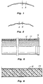
- figure 1 shows a little portion of a liner for a barrel of a composite material type which was manufactured before the invention
- figure 2 shows a liner for a corresponding barrel made by isostatic pressing according to the invention
- Figure 3 shows a cross section of a tool for isostatic pressing of a shell or a liner for a tube according to a first embodiment of the invention
- figure 4 correspondingly shows a second embodiment of a tool for isostatic pressing of a shell or a liner for a tube according to the invention.
- Figure 5 shows an axial cross section through a ready made tube according to the invention.
- Figure 6 correspondingly shows an axial cross section through a shaft made according to the invention.
- the basis of the invention is to make a shell or a liner of metal by isostatic pressing and on or in which shell or liner a high strength fiber material is wound or otherwise applied and is bound as conventional by means of a suitable resin.
- Isostatic pressing is known per se of means, in this case, that a tube having a substantially even thickness of material is applied in or on a preferably profiled mandrel of the same shape as the intended final shell or liner, whereupon the tool mandrel together with the shell blank is introduced or decended in a pressure chamber and is subjected to a liquid pressure by means of which the shell blank with a high pressure is pressed to the mandrel profilings thereby giving the shell the intended shape, eventually with a slight elastic re-deflexion of the blank material.
- Isostatic pressing can be made hot or cold, but cold pressing is to be preferred.
- Figure 1 shows a little portion of a liner for a barrel having inner rifles and made by chip cutting of a tube blank. It is obvious that the thickness of material at the notches is the same as the thickness of the original tube blank, whereas the cut recesses get a substantially reduced thickness of material.
- the barrel was made from a tube blank having a wall thickness of 1.5 mm and the recesses were cut down about 1 mm, that is so that the thickness of the material at the recesses is only about 0.5 mm.
- the said thickness of material is quite sufficient since the liner was wound with a high strength fiber material, but a weapon having such barrel has a limited shot capacity since the material at the recesses are subjected to strong stresses when shooting with a gun, especially elongation in the tangential direction and subsequent fatigue tendencies and fissure formations, whereas the material at the notches is substantially intact. In order to avoid that the weapon becomes too heavy it is wanted to keep the thickness of material as low as possible, and therefore it is considered disadvantageous to increase the thickness of material of the blank tube.
- the blank tube or "the liner” By forming the blank tube or "the liner" by isostatic pressing as shown in figure 2 according to the invention several advantages are obtained. Isostatic pressing is made quicker, more simpler and to a lower cost than the previously known chip cutting of the tube; there is a possibility of shaping the tube to very complicated shapes, for instance conical forms having rifles with a progessively increasing pitch; the starting object is a tube having a substantially even thickness of material, and also after the pressing the tube has still an even thickness of material; by the zig-zag shape of the formed liner the liner and thereby the entire barrel can become widened in the peripheral direction (radial direction) and it can contract elastically by a type of "harmonica effect" and still no parts of the liner is subjected to such stretching or elongations that the material becomes fatigued or get fissures, and therefore a barrel made according to the invention has a higher shot capacity and a longer life than barrels made according to previous methods.
- a tool is used for formning the liner, which tool may be of the inner pressed type as shown in figure 3 or the outer pressed type as shown in figure 4.
- the tool figure 3 comprises a mandrel 1 formed with rifles 2 or other profile formations. At each end there is a guide 3, and round the mandrel 1 and the guides 3 there is a tool of rubber type, for instance polyuretane and consisting of a cylindric sleeve 4, a top 5 and a bottom 6 which enclose the rubber sleeve 4 and seals thereto by means of sealing rings 7.
- a tool of rubber type for instance polyuretane and consisting of a cylindric sleeve 4, a top 5 and a bottom 6 which enclose the rubber sleeve 4 and seals thereto by means of sealing rings 7.
- a liner blank 8 is placed on the mandrel and is enclosed in the rubber mould 4-6, and the liner under the tool is decended in a pressure chamber (isostatic pressing bath) whereby the rubber sleeve 4 presses the liner blank 8 to the mandrel 1, so that the liner is formed like the mandrel, or instance with the form as indicated in figure 2.
- the mandrel is of split type and may comprise for instance 4 or 6 actual mandrels parts which are kept in correct position during the pressing by a support rod or by endguides.
- Figure 4 shows a tool for forming a liner inside a split or inner profiled formation tool which is supported between an inner rubber sleeve 10 and an outer sleeve 11, a rubber lid 12 and rubber bottom 4 which are sealed to the sleeves 10 and 11 by means of sealing rings 14.
- the pressing is made radially outwards to the inner profiled formation tool 9, and after the formpressing the liner 8 is released by separating the split parts of the formation tool 9.
- the inner rubber sleeve 10 is of slightly harder material than the outer sleeve 11, and the space between the inner sleeve 10 and the formation tool 9 is slightly greater than the space between the outer sleeve and the formation tool 9.
- the outer rubber sleeve 11 thereby compresses the actually split parts of the formation tool 9 so that the tool is tightly compressed and kept steadily before the inner sleeve 10 presses the liner 8 to the inner profiled pressing tool 9.
- the rubber sleeve in figure 3 can be excluded and the top 5 and the bottom 6 thereby seal directly to the liner.
- at least sleeve 10 can be excluded if a completely tight liner is used which can seal to the lid 12 and the bottom 13. It may in some cases be advantageous to exclude the rubber sleeve, for instance sharper edges are obtained in the pressed liner or shaft shell.
- a high strength fiber material like glassfiber, carbonfiber or any other highstrength fibers material which as conventionally is bound with a suitable plastic material, for instance a polyester resin and epoxy resin or a similar resin.
- the fiber material is wound in spiral formation round the liner and in several layers and is bound with a plastic binder.
- the fiber material gives a good strength in the tangential direction in which a profiled or rifled liner has a relatively weak strength.
- the fiber material on the contrary, gives a weak strength in the actual direction of the tube, but in this direction the tube or liner oppositely has a high strength.
- FIG. 5 shows a partial actual cross section through a ready liner according to the invention and as seen from the figure a fitting 16 is welded to the end of a liner 15, and the exterior of the liner is covered with a plastic bound fiber material 17.
- Figure 6 shows an actual cross section through a shaft made according to the invention and comprising an outer shaft shell 18 of an isostatic pressed blank which may have the intended profilings at the exterior thereof, and an inner filler material 19 of a suitable material, for instance a suitable plastic material.
- the shaft can be made so that the shaft blank is isostatic pressed as previously described and as shown in figure 3 or 4, where upon the cavities at the inner side of the shaft blank are filled with a mouldable material, for instance a plastic material, and in the inner actual cavity a filler material is introduced, which filler material can be mould in the cavity or can be formed to a rod which is pressed into this edge shaft cavity.
- a mouldable material for instance a plastic material
Landscapes
- Engineering & Computer Science (AREA)
- General Engineering & Computer Science (AREA)
- Manufacturing & Machinery (AREA)
- Mechanical Engineering (AREA)
- Moulding By Coating Moulds (AREA)
- Rigid Pipes And Flexible Pipes (AREA)
- Casting Or Compression Moulding Of Plastics Or The Like (AREA)
Claims (11)
Applications Claiming Priority (2)
| Application Number | Priority Date | Filing Date | Title |
|---|---|---|---|
| SE8503790 | 1985-08-13 | ||
| SE8503790A SE448282B (sv) | 1985-08-13 | 1985-08-13 | Forfarande for framstellning av ror eller axlar samt ror framstellt enligt forfarandet |
Publications (3)
| Publication Number | Publication Date |
|---|---|
| EP0213097A2 EP0213097A2 (de) | 1987-03-04 |
| EP0213097A3 EP0213097A3 (en) | 1987-05-06 |
| EP0213097B1 true EP0213097B1 (de) | 1989-05-17 |
Family
ID=20361086
Family Applications (1)
| Application Number | Title | Priority Date | Filing Date |
|---|---|---|---|
| EP86850260A Expired EP0213097B1 (de) | 1985-08-13 | 1986-07-16 | Verfahren und Vorrichtung zur Herstellung leichter Rohre oder Schäfte und dieselben erzeugt nach dieser Methode |
Country Status (4)
| Country | Link |
|---|---|
| US (1) | US4729806A (de) |
| EP (1) | EP0213097B1 (de) |
| DE (1) | DE3663399D1 (de) |
| SE (1) | SE448282B (de) |
Families Citing this family (20)
| Publication number | Priority date | Publication date | Assignee | Title |
|---|---|---|---|---|
| US5207848A (en) * | 1989-10-18 | 1993-05-04 | Rockwell International Corporation | Method of fabricating fiber reinforced metal tubes |
| US5054224A (en) * | 1990-11-19 | 1991-10-08 | The United States Of America As Represented By The Secretary Of The Army | Apparatus and method for a composite polymer rifling disposable gun tube |
| DE19505434C2 (de) * | 1995-02-17 | 1998-04-16 | Heckler & Koch Gmbh | Laufschiene für eine Schußwaffe und Verfahren zur Herstellung eines mit einer Laufschiene versehenen Laufes |
| US5600912A (en) * | 1995-11-29 | 1997-02-11 | Smith; David B. | Composite tube for a gun barrel |
| US6230429B1 (en) | 1999-06-30 | 2001-05-15 | Magnum Research, Inc. | Composite tube for gun barrel |
| FR2796997B1 (fr) * | 1999-07-26 | 2001-10-05 | Gitzo Holding | Ensemble comprenant un tube et un manchon |
| US6889464B2 (en) | 2003-06-04 | 2005-05-10 | Michael K. Degerness | Composite structural member |
| US20050108916A1 (en) * | 2003-08-28 | 2005-05-26 | Ra Brands, L.L.C. | Modular barrel assembly |
| US7546754B2 (en) * | 2005-04-14 | 2009-06-16 | Gm Global Technology Operations, Inc. | Method of fabricating tubular structure from hybrid material |
| US8418392B2 (en) * | 2007-08-13 | 2013-04-16 | The United States Of America As Represented By The Secretary Of The Army | Compressed elastomer process for autofrettage and lining tubes |
| US20060260374A1 (en) * | 2005-05-23 | 2006-11-23 | Flex-Weld, Inc. | Hydroforming machine |
| US20090011247A1 (en) * | 2007-07-02 | 2009-01-08 | Oil States Industries, Inc. | Molded Composite Mandrel for a Downhole Zonal Isolation Tool |
| US20150040454A1 (en) * | 2013-03-15 | 2015-02-12 | Saeilo Enterprises, Inc. | Injection molded gun barrel assembly |
| CN103292055B (zh) * | 2013-05-08 | 2014-12-17 | 河北华强科技开发有限公司 | 复合玻璃钢管及其制备方法 |
| US9796057B2 (en) | 2015-01-15 | 2017-10-24 | Saeilo Enterprises, Inc. | Gun barrel assembly |
| US11385013B2 (en) | 2016-07-01 | 2022-07-12 | Blackpowder Products, Inc. | Hybrid carbon—steel firearm barrel |
| US10890399B2 (en) * | 2018-07-02 | 2021-01-12 | Gog Paintball, S.A. | Barrel with rifling and method for forming |
| USD1018757S1 (en) | 2020-09-17 | 2024-03-19 | Blackpowder Products, Inc. | Firearm barrel |
| SE2300011A1 (sv) * | 2023-02-09 | 2024-08-10 | Bae Systems Bofors Ab | Eldrör |
| SE2400064A1 (sv) * | 2024-05-28 | 2025-11-11 | Bae Systems Bofors Ab | Eldrör samt metod för tillverkning av eldrörsegment |
Family Cites Families (12)
| Publication number | Priority date | Publication date | Assignee | Title |
|---|---|---|---|---|
| BE553418A (de) * | 1956-04-24 | |||
| US3517585A (en) * | 1966-03-10 | 1970-06-30 | Edwin Slade | Reinforced plastic tube and gun barrel construction incorporating an imbedded expandable woven screen lining |
| FR1597423A (de) * | 1968-07-18 | 1970-06-29 | ||
| US3571962A (en) * | 1969-06-10 | 1971-03-23 | Us Army | Monolithic metallic liner for fiberglass gun tubes |
| DE2525940A1 (de) * | 1975-06-11 | 1976-12-23 | Dynamit Nobel Ag | Waffenrohr |
| US4024008A (en) * | 1976-09-07 | 1977-05-17 | Honeywell Inc. | Plastic to metal bonding method |
| US4265951A (en) * | 1978-03-27 | 1981-05-05 | Celanese Corporation | Fiber reinforced composite shaft with metallic connector sleeves mounted by longitudinal groove interlock |
| DE2831148A1 (de) * | 1978-07-15 | 1980-01-24 | Skf Kugellagerfabriken Gmbh | Verfahren zur herstellung einer massiven aussenhuelse fuer eine kugelbuechse |
| US4238540A (en) * | 1979-05-29 | 1980-12-09 | Celanese Corporation | Fiber reinforced composite shaft with metallic connector sleeves mounted by connector ring interlock |
| JPS59501152A (ja) * | 1982-02-02 | 1984-07-05 | フイジコ−チエフニチエスキ− インスチツ−ト アカデミ− ナウク ベロルススコイ エスエスエル | 管成形装置 |
| SE443100B (sv) * | 1982-03-26 | 1986-02-17 | Sven Runo Vilhelm Gebelius | Sett att framstella ett koniskt rorformigt element jemte element framstellt enligt settet |
| DE3212721A1 (de) * | 1982-04-05 | 1983-10-20 | Dynamit Nobel Ag, 5210 Troisdorf | Abschussrohr fuer flugkoerper |
-
1985
- 1985-08-13 SE SE8503790A patent/SE448282B/sv not_active IP Right Cessation
-
1986
- 1986-07-16 DE DE8686850260T patent/DE3663399D1/de not_active Expired
- 1986-07-16 EP EP86850260A patent/EP0213097B1/de not_active Expired
- 1986-08-12 US US06/895,887 patent/US4729806A/en not_active Expired - Fee Related
Also Published As
| Publication number | Publication date |
|---|---|
| EP0213097A3 (en) | 1987-05-06 |
| EP0213097A2 (de) | 1987-03-04 |
| SE448282B (sv) | 1987-02-09 |
| US4729806A (en) | 1988-03-08 |
| SE8503790D0 (sv) | 1985-08-13 |
| DE3663399D1 (en) | 1989-06-22 |
Similar Documents
| Publication | Publication Date | Title |
|---|---|---|
| US4729806A (en) | Method for making tubes having low weight | |
| CA1167676A (en) | Rifled fiber reinforced gun barrel | |
| US4014184A (en) | Propeller shaft liner and inserting apparatus | |
| US5600912A (en) | Composite tube for a gun barrel | |
| US5415079A (en) | Composite cylinder for use in aircraft hydraulic actuator | |
| EP0170353A1 (de) | Abschnitt eines Laufes und Verfahren zu seiner Herstellung | |
| US6523476B1 (en) | Ammunition with a shell whose wall consists of combustible or consumable wound body | |
| US2845741A (en) | Composite firearm barrel | |
| US3242789A (en) | Method of making plastic cartridge case | |
| US2847786A (en) | Composite firearm barrel comprising glass fibers | |
| US5280706A (en) | Composite/metal hybrid rocket motor case and methods for manufacturing | |
| US5544805A (en) | Method of producing a fibre-reinforced metallic circular part | |
| US2996988A (en) | Cartridge for firearms having sideloaded firing chambers | |
| US3228298A (en) | Rifle barrel | |
| US5804756A (en) | Composite/metallic gun barrel having matched coefficients of thermal expansion | |
| US5642851A (en) | Method of producing a circular fibre-reinforced metal article, and apparatus for use in said method | |
| AU604652B2 (en) | Improved gun barrel construction | |
| US3450050A (en) | Salvo squeezebore projectiles | |
| US4907736A (en) | Method of forming articles | |
| US5054224A (en) | Apparatus and method for a composite polymer rifling disposable gun tube | |
| EP0479746B1 (de) | Faserverstärkter gezogener Gewehrlauf | |
| NL8403125A (nl) | Vezelversterkt kunststof drukvat. | |
| US4614631A (en) | Process for screw-cutting in a tube or link made from a composite carbon fiber based material coated with polymerized resin | |
| US20030221580A1 (en) | Tapered powder-based core for projectile | |
| US3439620A (en) | Projectile driving bands |
Legal Events
| Date | Code | Title | Description |
|---|---|---|---|
| PUAI | Public reference made under article 153(3) epc to a published international application that has entered the european phase |
Free format text: ORIGINAL CODE: 0009012 |
|
| AK | Designated contracting states |
Kind code of ref document: A2 Designated state(s): CH DE FR GB LI SE |
|
| PUAL | Search report despatched |
Free format text: ORIGINAL CODE: 0009013 |
|
| AK | Designated contracting states |
Kind code of ref document: A3 Designated state(s): CH DE FR GB LI SE |
|
| 17P | Request for examination filed |
Effective date: 19870828 |
|
| 17Q | First examination report despatched |
Effective date: 19880425 |
|
| GRAA | (expected) grant |
Free format text: ORIGINAL CODE: 0009210 |
|
| AK | Designated contracting states |
Kind code of ref document: B1 Designated state(s): CH DE FR GB LI SE |
|
| PG25 | Lapsed in a contracting state [announced via postgrant information from national office to epo] |
Ref country code: SE Effective date: 19890517 |
|
| REF | Corresponds to: |
Ref document number: 3663399 Country of ref document: DE Date of ref document: 19890622 |
|
| ET | Fr: translation filed | ||
| PLBE | No opposition filed within time limit |
Free format text: ORIGINAL CODE: 0009261 |
|
| STAA | Information on the status of an ep patent application or granted ep patent |
Free format text: STATUS: NO OPPOSITION FILED WITHIN TIME LIMIT |
|
| 26N | No opposition filed | ||
| PGFP | Annual fee paid to national office [announced via postgrant information from national office to epo] |
Ref country code: FR Payment date: 19920630 Year of fee payment: 7 |
|
| PGFP | Annual fee paid to national office [announced via postgrant information from national office to epo] |
Ref country code: GB Payment date: 19920715 Year of fee payment: 7 |
|
| PGFP | Annual fee paid to national office [announced via postgrant information from national office to epo] |
Ref country code: DE Payment date: 19920824 Year of fee payment: 7 |
|
| PGFP | Annual fee paid to national office [announced via postgrant information from national office to epo] |
Ref country code: CH Payment date: 19920924 Year of fee payment: 7 |
|
| PG25 | Lapsed in a contracting state [announced via postgrant information from national office to epo] |
Ref country code: GB Effective date: 19930716 |
|
| PG25 | Lapsed in a contracting state [announced via postgrant information from national office to epo] |
Ref country code: LI Effective date: 19930731 Ref country code: CH Effective date: 19930731 |
|
| GBPC | Gb: european patent ceased through non-payment of renewal fee |
Effective date: 19930716 |
|
| PG25 | Lapsed in a contracting state [announced via postgrant information from national office to epo] |
Ref country code: FR Effective date: 19940331 |
|
| REG | Reference to a national code |
Ref country code: CH Ref legal event code: PL |
|
| PG25 | Lapsed in a contracting state [announced via postgrant information from national office to epo] |
Ref country code: DE Effective date: 19940401 |
|
| REG | Reference to a national code |
Ref country code: FR Ref legal event code: ST |