EP0212995A2 - Sight fixation system for ophthalmic instruments - Google Patents
Sight fixation system for ophthalmic instruments Download PDFInfo
- Publication number
- EP0212995A2 EP0212995A2 EP86401306A EP86401306A EP0212995A2 EP 0212995 A2 EP0212995 A2 EP 0212995A2 EP 86401306 A EP86401306 A EP 86401306A EP 86401306 A EP86401306 A EP 86401306A EP 0212995 A2 EP0212995 A2 EP 0212995A2
- Authority
- EP
- European Patent Office
- Prior art keywords
- fixation
- instrument according
- optical axis
- ophthalmologic instrument
- eye
- Prior art date
- Legal status (The legal status is an assumption and is not a legal conclusion. Google has not performed a legal analysis and makes no representation as to the accuracy of the status listed.)
- Granted
Links
Images


Classifications
-
- A—HUMAN NECESSITIES
- A61—MEDICAL OR VETERINARY SCIENCE; HYGIENE
- A61B—DIAGNOSIS; SURGERY; IDENTIFICATION
- A61B3/00—Apparatus for testing the eyes; Instruments for examining the eyes
- A61B3/10—Objective types, i.e. instruments for examining the eyes independent of the patients' perceptions or reactions
Definitions
- This invention relates to a fixation sight apparatus for ophthalmologic instrument to be used for such ophthalmologic instrument as retinal camera, refractometer, tonometer, perimeter, etc. in order to have an eye to be tested fixedly sight or gaze at a fixation mark.
- ophthalmologic instrument for having a person to be tested fixedly sight or gaze at a fixation mark.
- a diopter correction mechanism is provided so that even if the eye to be tested is an ametropia eye, i.e., ametropia and is a myopia eye or hyperopia eye, eye to be tested can gaze at the fixation mark.
- Two different systems of diopter correction mechanisms are known; one is of the system that a plurality of correction lenses having different refractive powers with respect to one another are selectively inserted into an optical path of a fixation sight apparatus, and the other is of the system that either one or both of the fixation mark image and the projection lens adapted to project the fixation mark image to the eye to be tested (eye to be fixedly sighted or gazed at) are simultaneously moved in the optical axis direction thereof to optically position the fixation mark in a far point position of the eye to be tested.
- the latter system is constituted as such that the eye can fixedly sight or gaze at the fixation mark with least accommodation of the eye by optically moving the fixation mark from a position nearer than the far point of the eye to a position farther than the far point position on the optical axis via the far point position on the optical axis by moving the projection lens.
- the conventional fixation sight apparatus for ophthalmologic instrument including any of the above- mentioned diopter correcting mechanisms is complicated in its structure due to the complicated structure of the diopter mechanism employed therein and also the employment of actuation means for actuating the projection lens, correction lens, etc.
- the deed itself of fixation sight of tne eye to be tested is a secondary one in the light of the main measuring and testing deeds of the ophthalmologic instrument including the fixation sight apparatus, in spite of the foregoing, such a diopter correction operation as to actuate the projection lens and the correction lens using the diopter correction mechanism in order to correct the diopter of the eye is required to be effected every time the measurement and testing are carried out, which causes the measurer much inconveniences.
- the results corrected by means of the diopter correction operation are required to be confirmed through question and answer between the measurer and the person to be tested. This confirmation deed is troublesome.
- the corrected results relies on only the response of the person to be tested, the accuracy thereof is dubious.
- the present invention is accomplished in view of the above situation. It is therefore an object of the present invention to provide a fixation sight apparatus for ophthalmologic instrument, wherein an eye to be tested is enabled to fixedly sight or gaze at a fixation mark without a troublesome operation of diopter correction.
- Another object of the present invention is to provide a fixation sight apparatus for ophthalmologic instrument, wherein a fixation mark is presented in such a manner as to adequately decrease the adjusting power of an eye to be tested.
- the present invention is accomplished by giving a special attention to the sight confirmation characteristic that when there are presented two images of generally icentical sized-objects overlapping one upon the other, one image being clear and the other being vague, a human brain potentially selects the clear image and brings the attention of the eye to the clear one. It is therefore the feature of a fixation sight apparatus for ophthalmologic instrument according to the present invention that presentation means adapted to present a plurality of fixation mark images is provided on a measuring optical axis.
- the fixation sight apparatus for ophthalmologic instrument according to the present invention, includes no movable mechanism. Accordingly, the constitution is comparably simple when compared with the conventional apparatus. Further, according to the sight confirmation characteristic of the eye to be tested, the most clearly sightable fixation mark image among many fixation mark images can be selected for fixation sight. Accordingly, the question and answer exchanged between the tester and the person to be tested and a correction operation accompanied thereto are no more required.
- Figs. 1 through 3 illustrate a first embodiment of a fixation sight apparatus for ophthalmologic instrument according to the present invention.
- reference numeral 10 denotes a fixation optical system of the fixation sight apparatus for ophthalmologic instrument.
- An optical axis O 1 of tnis fixation optical system 10 and an optical axis 0 2 of a main optical system 100 of ophthalmologic instrument having this fixation optical system 10 are disposed on one straight line in this embodiment.
- Reference symbolic character E denotes an eye to be tested which is disposed on the optical axis O 1 .
- a projection lens 11 is disposed at a space d in the optical axis direction from the eye.
- Half mirrors 12, 13 and 14 are disposed respectively behind the projection lens 11 at spaces ⁇ 1 , ⁇ 2 and ⁇ 3 along the optical axis O i . These half mirrors 12, 13 and 14 are inclined at angles witn respect to the optical axis O 1 .
- light emitting diodes 15, 16 and 17 functioning as fixation marks are disposed.
- the respective anode terminals of the light emitting diodes 15, 16 and 17 are connected with variable resistors 18, 19 and 20 respectively.
- the light emitting diodes 15, 16 and 17 are adjusted the brightness thereof by adjusting the variable resistors 18, 19 and 20, such that wnen the light emitting quantity of the light emitting diodes 15, 16 and 17 becomes adequate with respect to the diopter of the eye E to be tested, the brightness of the entire fixation marks becomes equal to the eye E.
- reference character A denotes a fixation mark based on the light emitting diode 15 formed on the optical axis O 1 .
- the fixation mark is formed as a virtual image on the optical axis O 1 behind the half mirror 12 by the distance h.
- the emitted light from the light emitting diode 16 transmits the half mirror 12 after reflected by the half mirror 13, is guided to the projection lens 11 and projected toward the eye E by the projection lens 11.
- reference character B denotes a fixation mark based on the light emitting diode 16 formed on the optical axis O 1 .
- the fixation mark B is formed as a virtual image behind the half mirror 13 and away therefrom by a space h according to the principle of mirror symmetry.
- the position of the fixation mark B coincides with the focussing distance f of the projection lens 11.
- the emitted light from the light emitting diode 17 transmits the half mirrors 13 and 12 in this order after reflected by the half mirror 13, is guided to the projection lens 11 and projected to the eye E to be tested by the projection lens 11.
- reference character C denotes a fixation mark based on the light emitting diode 17 formed on the optical axis O 1 .
- the fixation marks A, B and C are simultaneously presented on the optical axis O 1 .
- the light emitting diodes 15, 16 and 17 and the half mirrors 12, 13 and 14 generally constitute a presentation means for presenting the plurality of fixation mark images on the optical axis O 1 .
- this fixation mark B since the fixation mark B is located in the focussing position of the projection lens 11, this fixation mark B renders a fixation mark image B 1 optically conjugated with the retina X of the eye E to be tested of an emmetropia (0 diopter of refractive power) as shown in Fig. 2.
- the eye E to be tested when the eye E to be tested is a strong myopia, the eye E fixedly sights or gazes at the fixation mark image A 1 and when the eye E is a strong hyperopia, it fixedly sights or gazes at the fixation mark image C 1 .
- variable resisters, 18, 19 and 20 are used for adjusting the light emitting quantity of the light emitting diodes 15, 16 and 17.
- suitable methods such as a method for varying the duty ratio of the light emitting diodes 15, 16 and 17 and a method for maintaining a difference in reflection or transmission of the respective half mirrors 12, 13 and 14 may be employed.
- Figs. 4 and 5 illustrate a second embodiment of a fixation sight apparatus for ophthalmologic instrument according to the present invention.
- the optical axis O 1 of the fixation sight apparatus for ophthalmoiogic instrument is divided into an optical axis O 11 and an optical axis 0 12 by a nalf mirror 21, wnile the optical axis O 12 and a main optical axis 0 2 of the main optical system 100 of the ophthalmologic instrument are composed by the half mirror 21.
- a projection lens 11, half mirrors 22, 23 and 24, a target plate 25, a diffusion plate 26 and an incandescent lamp 27 are disposed on the optical axis O 11 of the fixation sight apparatus of ophthalmologic instrument.
- the light emitted from the incandescent lamp 27 illuminates a target plate 25 after diffused into a diffusion light by a diffusion plate 26.
- the target plate 25 is formed with a ring-shaped fixation mark 25a as shown in Fig. 5.
- Tne light transmitted this fixation mark 25a simultaneously advances four optical paths comprising a first optical path P 1 in which the light transmits the half mirrors 24, 23 and 22 disposed on the optical axis O 11 and reaches the projection lens 11, a second optical path P 2 in which the light is reflected by the half mirror 24, guided to the half mirror 22 through total reflection mirrors 28, 29 and the half mirror 23, transmits the half mirror 22 and reaches the projection lens 11, a third optical path P 3 in which the light is reflected by the half mirror 24, transmits the half mirror 23 after reflected by the total reflection mirrors 28 and 29, guided to the half mirror through total reflection mirrors 30, 31 and guided to the projection lens 11 by the half mirror 22, and a fourth optical path P 4 in which the light is reflected by the half mirror 23, the total reflection mirrors 30 and 31 and the half mirror 22 after transmitting the half mirror 24 and guided to the projection lens 11.
- Fig. 6 illustrates a third embodiment of a fixation sight apparatus for ophthalmologic instrument according to the present invention, wherein partial mirrors 32 and 33 are used instead of the half mirrors 12, 13 and 14 of the first embodiment.
- two incandescent lamps are provided.
- the light emitted from the incandescent lamps is diffused by a diffusion plate 26.
- a target plate 25 is formed with three fixation marks 25b, 25c and 25d.
- the ⁇ target plate 25 is attached to the diffusion plate 26.
- the diffusion light illuminates the fixation marks 25b, 25c and 25d.
- the partial mirrors 32 and 33 are disposed on the optical axis O 1 of the fixation sight apparatus of opnthalmologic instrument.
- a total reflection mirror 34 is disposed behind the partial mirrors 32 and 33.
- the partial mirrors 32 and 33 partially have reflection films 32a, 33a on a transparent glass and are inclined at angles with respect to the optical axis.
- the reflection film 32a of the partial mirror 32 and the reflection film 33a of the partial mirror 33 are formed within an area where they do not optically interfere with respect to each other and within a very small area close to the optical axis 0 1 disposed therebetween.
- the respective fixation marks 25b, 25c and 25d are located on the incidence optical axes 32b, 33b and 34b of the respective mirrors 32, 33 and 34.
- the focal point of the projection lens 11 is in an optically conjugated position with the fixation mark 25c of the incidence optical axis 33b in the same manner as the
- the projection lens 11 projects a fixation light formed by three fixation marks 25b, 25c and 25d toward the eye E to be tested to form three fixation mark images A 1 , B 1 and C 1 on the optical axis O 1 in the same manner as the first embodiment.
- the eye to be tested naturally fixedly gazes at the fixation mark image nearest to the far point which the eye E itself has.
- a plurality of fixation mark images are simultaneously presented on the optical axis O 1 of the fixation sight apparatus for ophthalmologic instrument in order to have the eye E to be tested (eye to be fixedly sighted or gazed at) confirm them by sight.
- the present invention is not limited to the foregoing.
- additional constitution is employed in addition to the constitution of the first through the third empodiments in order to selectively present the fixation mark images to the eye E to be tested.
- a foggy sight Like sight fixation means in which the order for the presentation is predetermined to remove the accommodation of the eye E and have-the eye E fixedly sight or gaze at the fixation mark.
- Fig. 7 illustrates a modified embodiment of the first embodiment and is a circuit for showing the constitution for selectively presenting the fixation mark images to the eye E to be tested.
- identical constitutional elements as those of the first embodiment are denoted by the identical numerals or characters as those used- in the first embodiment, and the detailed description on them will be omitted. Instead, only different constitution will be described.
- a switch 35 is interposed between a (+) anode terminal of an electric power source and light emitting diodes 15, 16 and 17, a switch 35 is interposed.
- the switch 35 has three terminals 36, 37 and 38.
- the terminal 36 is connected with an anode of the light emitting diode 15 through a variable resister 18
- the terminal 37 is connected with an anode of the light emitting diode 16 through a variable resister 19
- the terminal 38 is connected with an anode of the light emitting diode through a variable resister 20.
- the light emitting diodes 15, 16 and 17 can be selectively lightened by switching the switch 35 in order. Accordingly, the fixation mark images can be selectively presented to the eye E to be tested. Particularly, if the switch 35 is turned in the clockwise direction to switch in turn as shown in Fig. 7, the fixation mark images A 1 , B 1 and C 1 are presented in such order as starting from the far point position of myopia via the far point position of emmetropia and to the far point position of hyperopia. Accordingly, the eye E to be tested fixedly sighting or gazing at the image is decreased its accommodation, thereby to enable to fixedly sight or gaze in a state near to non-accommodation. Thus, a foggy sight like fixation sight.is obtainable.
- the switching operation of the switch 35 may be effected manually or automatically. For example, it can be automatically operated by connecting it to a CPU circuit wnicn the ophthalmologic instrument has.
- the modified embodiments are constituted as such that as shown in Figs. 4 and 6, liquid crystal shutters 39 through 45 are arranged within the optical path and the fixation mark images are selectively presented to the eye E to be tested by putting on or off the liquid crystal shutters 39 through 45.
- liquid crystal shutters 39 through 45 are arranged within the optical path and the fixation mark images are selectively presented to the eye E to be tested by putting on or off the liquid crystal shutters 39 through 45.
- One such example will be described with reference to the modified emoodiment shown in Fig. 4. If the shutters 39, 41 are put on and the shutter 40 is put off, only the first optical path P 1 is selected. If the shutters 40, 41 are put on and the shutter 39 is put off, only the second optical path P 2 is selected.
- the fixation mark images A 1 , B 1 and C 1 are presented starting from the far point of myopia to the far point of hyperopia, thereby to enable to have the eye E to be tested effect a foggy sight like fixation sight.
- Figs. 8 through 10 illustrate a fifth embodiment of an fixation sight apparatus for ophthalmologic instrument according to the present invention.
- a plane parallel glass plate 45 is disposed in such a manner as to be perpendicular to the optical axis O 1 .
- both surfaces of the plane parallel 45 serve as half mirror surfaces 45a and 45b.
- the light emitting diode 15 is disposed at the focal point of the projection lens 11.
- a part of the light emitted from the light emitting diode 15 is allowed to transmit the plane parallel 45 as it is.
- the remaining emitted light transmits the plane parallel 45 and is guided to the projection lens 11 after reflected a plurality of times on the half mirror surfaces 45a and 45b. Accordingly, an infinite number of fixation marks A, B, C, D... are formed on the optical axis O 1 as shown in Fig. 10.
- reference character Y denotes an optical position of the projection lens 11.
- the relation between the retina X of the eye E to be tested and the fixation mark images A 1 , B 1 , C 1 . D 1 , E 1 ...positioned in optically conjugated point with respect to the retina X is shown in Fig. 9.
- the eye E fixedly sights or gazes at one fixation mark image positioned nearest to the optically conjugated point of its own retina X, at the time when no accommodation is effected, among these fixation mark images.
- a light quantity attenuation is taken place due to plural times of reflection and transmission through the half mirror surfaces 45a and 45b and the brightness of the fixation marks A, B, C, D... is decreased in turn. Accordingly, in order to prevent the occurrence of the light quantity attenuation, the reflectance of the half mirror surfaces 45a and 45b is set as 5% and the transmittance is set as 95% in this embodiment.
- Fig. 11 illustrates an embodiment showing a first modified embodiment of the fifth embodiment, wherein a diffusion plate 46 is disposed between the light emitting diode 15 and the plane parallel 45.
- a pin hole plate 47 is placed in contact with the diffusion plate 46.
- the pin hole plate 47 is formed with a pin hole 47a.
- the size of the pin hole represents the size of the fixation mark. If the constitution of this embodiment is combined with the afore-mentioned constitution in which the light emitting diode 15 itself is directly used as a fixation mark, freedom for selecting the size of the fixation mark is increased.
- Fig. 12 illustrates an embodiment showing a second modified embodiment of the fifth embodiment, wherein only a front surface 48 of the plane parallel 45 is served as a half mirror surface, a rear surface 49 is served as a total reflection surface having a pin hole 50 on the optical axis O 1 .
Landscapes
- Life Sciences & Earth Sciences (AREA)
- Health & Medical Sciences (AREA)
- Medical Informatics (AREA)
- Biophysics (AREA)
- Ophthalmology & Optometry (AREA)
- Engineering & Computer Science (AREA)
- Biomedical Technology (AREA)
- Heart & Thoracic Surgery (AREA)
- Physics & Mathematics (AREA)
- Molecular Biology (AREA)
- Surgery (AREA)
- Animal Behavior & Ethology (AREA)
- General Health & Medical Sciences (AREA)
- Public Health (AREA)
- Veterinary Medicine (AREA)
- Eye Examination Apparatus (AREA)
Abstract
Description
- This invention relates to a fixation sight apparatus for ophthalmologic instrument to be used for such ophthalmologic instrument as retinal camera, refractometer, tonometer, perimeter, etc. in order to have an eye to be tested fixedly sight or gaze at a fixation mark.
- Heretofore, there has been put into actual use an ophthalmologic instrument for having a person to be tested fixedly sight or gaze at a fixation mark. In most opntnalmologic instrument, a diopter correction mechanism is provided so that even if the eye to be tested is an ametropia eye, i.e., ametropia and is a myopia eye or hyperopia eye, eye to be tested can gaze at the fixation mark.
- Two different systems of diopter correction mechanisms are known; one is of the system that a plurality of correction lenses having different refractive powers with respect to one another are selectively inserted into an optical path of a fixation sight apparatus, and the other is of the system that either one or both of the fixation mark image and the projection lens adapted to project the fixation mark image to the eye to be tested (eye to be fixedly sighted or gazed at) are simultaneously moved in the optical axis direction thereof to optically position the fixation mark in a far point position of the eye to be tested. Particularly, the latter system is constituted as such that the eye can fixedly sight or gaze at the fixation mark with least accommodation of the eye by optically moving the fixation mark from a position nearer than the far point of the eye to a position farther than the far point position on the optical axis via the far point position on the optical axis by moving the projection lens.
- However, the conventional fixation sight apparatus for ophthalmologic instrument including any of the above- mentioned diopter correcting mechanisms is complicated in its structure due to the complicated structure of the diopter mechanism employed therein and also the employment of actuation means for actuating the projection lens, correction lens, etc.
- Further, although the deed itself of fixation sight of tne eye to be tested is a secondary one in the light of the main measuring and testing deeds of the ophthalmologic instrument including the fixation sight apparatus, in spite of the foregoing, such a diopter correction operation as to actuate the projection lens and the correction lens using the diopter correction mechanism in order to correct the diopter of the eye is required to be effected every time the measurement and testing are carried out, which causes the measurer much inconveniences.
- Moreover, the results corrected by means of the diopter correction operation are required to be confirmed through question and answer between the measurer and the person to be tested. This confirmation deed is troublesome. In addition, since the corrected results relies on only the response of the person to be tested, the accuracy thereof is dubious.
- The present invention is accomplished in view of the above situation. It is therefore an object of the present invention to provide a fixation sight apparatus for ophthalmologic instrument, wherein an eye to be tested is enabled to fixedly sight or gaze at a fixation mark without a troublesome operation of diopter correction.
- Another object of the present invention is to provide a fixation sight apparatus for ophthalmologic instrument, wherein a fixation mark is presented in such a manner as to adequately decrease the adjusting power of an eye to be tested.
- The present invention is accomplished by giving a special attention to the sight confirmation characteristic that when there are presented two images of generally icentical sized-objects overlapping one upon the other, one image being clear and the other being vague, a human brain potentially selects the clear image and brings the attention of the eye to the clear one. It is therefore the feature of a fixation sight apparatus for ophthalmologic instrument according to the present invention that presentation means adapted to present a plurality of fixation mark images is provided on a measuring optical axis.
- In the fixation sight apparatus for ophthalmologic instrument according to the present invention, the fixation sight apparatus includes no movable mechanism. Accordingly, the constitution is comparably simple when compared with the conventional apparatus. Further, according to the sight confirmation characteristic of the eye to be tested, the most clearly sightable fixation mark image among many fixation mark images can be selected for fixation sight. Accordingly, the question and answer exchanged between the tester and the person to be tested and a correction operation accompanied thereto are no more required.
- The above and other objects, features and advantages of the present invention will become more apparent to those skilled in the art from the following detailed description of the embodiments of the present invention, when taken in conjunction with the accompanying drawings, wherein:
-
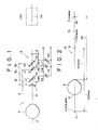
- Fig. 1 is an illustration of an optical system according to a first embodiment of the present invention;
- Fig. 2 is a schematic illustration for explaining the positional relation of an optically conjugating point of a fixation mark image with respect to the retina of an eye to be tested shown in Fig. 1;
- Fig. 3 is an illustration showing the position of a fixation mark image formed by light emitting diode shown in Fig. 1;
- Fig. 4 is an illustration of an optical system for explaining a fixation sight apparatus for ophthalmologic instrument according to a second and a fourth embodiment of the present invention;
- Fig. 5 is a plan view showing one example of a target plate shown in Fig. 4;
- Fig. 6 is an illustration of a circuit for explaining a fixation sight apparatus for ophthalmologic instrument according to a fourtn embodiment of the present invention;
- Fig. 7 is an illustration of an optical system for explaining a fixation sight apparatus for ophthalmologic instrument according to a third embodiment of the present invention;
- Fig. 8 is an illustration of an optical system for explaining a fixation sight apparatus for ophthalmologic instrument according to a fifth embodiment of the present invention;
- Fig. 9 is a schematic illustration for explaining the relation in the optically conjugating point between the retina of the eye to be tested and the fixation mark image shown in Fig. 8;
- Fig. 10 is an illustration of an optical system showing a fixation sight apparatus for ophthalmologic instrument according to a sixth embodiment of the present invention;
- Fig. 11 is an illustration of an optical system showing a fixation sight apparatus for ophthalmologic instrument according to a seventh embodiment of the present invention; and
- Fig. 12 is an illustration of an optical system showing a fixation sight apparatus for ophthalmologic instrument according to a sixth embodiment of the present invention.
- A first through a seventh embodiments of a fixation sight apparatus for ophthalmologic instrument according to the present invention will be described with reference to the accompanying drawings.
- Figs. 1 through 3 illustrate a first embodiment of a fixation sight apparatus for ophthalmologic instrument according to the present invention. In Fig. 1,
reference numeral 10 denotes a fixation optical system of the fixation sight apparatus for ophthalmologic instrument. An optical axis O1 of tnis fixationoptical system 10 and an optical axis 02 of a mainoptical system 100 of ophthalmologic instrument having this fixationoptical system 10 are disposed on one straight line in this embodiment. Reference symbolic character E denotes an eye to be tested which is disposed on the optical axis O1. A projection lens 11 is disposed at a space d in the optical axis direction from the eye.Half mirrors half mirrors - On the respective incidence optical axes 03, 04 and O5 of the
half mirrors light emitting diodes light emitting diodes variable resistors light emitting diodes variable resistors light emitting diodes - The
light emitting diodes light emitting diode 15 is reflected by thehalf mirror 12 projected toward the eye E by the projection lens 11. In Fig. 3, reference character A denotes a fixation mark based on thelight emitting diode 15 formed on the optical axis O1. The fixation mark is formed as a virtual image on the optical axis O1 behind thehalf mirror 12 by the distance h. The emitted light from thelight emitting diode 16 transmits thehalf mirror 12 after reflected by thehalf mirror 13, is guided to the projection lens 11 and projected toward the eye E by the projection lens 11. In Fig. 3, reference character B denotes a fixation mark based on thelight emitting diode 16 formed on the optical axis O1. The fixation mark B is formed as a virtual image behind thehalf mirror 13 and away therefrom by a space h according to the principle of mirror symmetry. The position of the fixation mark B coincides with the focussing distance f of the projection lens 11. The emitted light from thelight emitting diode 17 transmits thehalf mirrors half mirror 13, is guided to the projection lens 11 and projected to the eye E to be tested by the projection lens 11. In Fig. 3, reference character C denotes a fixation mark based on thelight emitting diode 17 formed on the optical axis O1. - Due to the simultaneous lightening of these
light emitting diodes light emitting diodes half mirrors - Due to the foregoing, for example, when the eye E is an emmetropia, a weak myopia, or a weak hyperopia, this eye E can clearly see the fixation mark image B1 by comparing the other two fixation mark images A1 and C1. Accordingly, the eye E fixedly sighted or gazed at tne fixation mark image B1.
- On tne other hand, when the eye E to be tested is a strong myopia, the eye E fixedly sights or gazes at the fixation mark image A1 and when the eye E is a strong hyperopia, it fixedly sights or gazes at the fixation mark image C 1.
- In this embodiment, in order to avoid the differences of the brightness of the fixation mark images A1, B1 and C1, the variable resisters, 18, 19 and 20 are used for adjusting the light emitting quantity of the
light emitting diodes light emitting diodes - Figs. 4 and 5 illustrate a second embodiment of a fixation sight apparatus for ophthalmologic instrument according to the present invention. The optical axis O1 of the fixation sight apparatus for ophthalmoiogic instrument is divided into an optical axis O11 and an optical axis 012 by a
nalf mirror 21, wnile the optical axis O12 and a main optical axis 02 of the mainoptical system 100 of the ophthalmologic instrument are composed by thehalf mirror 21. A projection lens 11, half mirrors 22, 23 and 24, atarget plate 25, adiffusion plate 26 and anincandescent lamp 27 are disposed on the optical axis O11 of the fixation sight apparatus of ophthalmologic instrument. The light emitted from theincandescent lamp 27 illuminates atarget plate 25 after diffused into a diffusion light by adiffusion plate 26. Thetarget plate 25 is formed with a ring-shapedfixation mark 25a as shown in Fig. 5. - Tne light transmitted this
fixation mark 25a simultaneously advances four optical paths comprising a first optical path P1 in which the light transmits the half mirrors 24, 23 and 22 disposed on the optical axis O11 and reaches the projection lens 11, a second optical path P2 in which the light is reflected by thehalf mirror 24, guided to thehalf mirror 22 through total reflection mirrors 28, 29 and thehalf mirror 23, transmits thehalf mirror 22 and reaches the projection lens 11, a third optical path P3 in which the light is reflected by thehalf mirror 24, transmits thehalf mirror 23 after reflected by the total reflection mirrors 28 and 29, guided to the half mirror through total reflection mirrors 30, 31 and guided to the projection lens 11 by thehalf mirror 22, and a fourth optical path P4 in which the light is reflected by thehalf mirror 23, the total reflection mirrors 30 and 31 and thehalf mirror 22 after transmitting thehalf mirror 24 and guided to the projection lens 11. Due to the foregoing, four fixation mark images are formed on the optical axis 01. And, if the focal length f of the projection lens 11 is set to be equal to the optical path lengtn of, for example, the second optical path P2, the eye E to be tested naturally fixedly sights or gazes at the fixation mark image nearest to the far point of the eye among the simultaneously presented four fixation mark images in the same manner as the first embodiment. - Fig. 6 illustrates a third embodiment of a fixation sight apparatus for ophthalmologic instrument according to the present invention, wherein
partial mirrors diffusion plate 26. Atarget plate 25 is formed with threefixation marks \ target plate 25 is attached to thediffusion plate 26. The diffusion light illuminates the fixation marks 25b, 25c and 25d. The partial mirrors 32 and 33 are disposed on the optical axis O1 of the fixation sight apparatus of opnthalmologic instrument. Atotal reflection mirror 34 is disposed behind thepartial mirrors reflection films - The
reflection film 32a of thepartial mirror 32 and thereflection film 33a of thepartial mirror 33 are formed within an area where they do not optically interfere with respect to each other and within a very small area close to the optical axis 01 disposed therebetween. On the incidenceoptical axes respective mirrors fixation mark 25c of the incidenceoptical axis 33b in the same manner as the - Due to the foregoing constitution, the projection lens 11 projects a fixation light formed by three
fixation marks - In the first through the third embodiments, a plurality of fixation mark images are simultaneously presented on the optical axis O1 of the fixation sight apparatus for ophthalmologic instrument in order to have the eye E to be tested (eye to be fixedly sighted or gazed at) confirm them by sight. However, the present invention is not limited to the foregoing. There will be described another embodiment hereinafter in which additional constitution is employed in addition to the constitution of the first through the third empodiments in order to selectively present the fixation mark images to the eye E to be tested. Further, there will be described a foggy sight Like sight fixation means in which the order for the presentation is predetermined to remove the accommodation of the eye E and have-the eye E fixedly sight or gaze at the fixation mark.
- (1) Fig. 7 illustrates a modified embodiment of the first embodiment and is a circuit for showing the constitution for selectively presenting the fixation mark images to the eye E to be tested. In Fig. 7, identical constitutional elements as those of the first embodiment are denoted by the identical numerals or characters as those used- in the first embodiment, and the detailed description on them will be omitted. Instead, only different constitution will be described.
- In this modified embodiment, between a (+) anode terminal of an electric power source and
light emitting diodes switch 35 is interposed. Theswitch 35 has threeterminals light emitting diode 15 through avariable resister 18, the terminal 37 is connected with an anode of thelight emitting diode 16 through avariable resister 19 and the terminal 38 is connected with an anode of the light emitting diode through avariable resister 20. - With this constitution, the
light emitting diodes switch 35 in order. Accordingly, the fixation mark images can be selectively presented to the eye E to be tested. Particularly, if theswitch 35 is turned in the clockwise direction to switch in turn as shown in Fig. 7, the fixation mark images A1, B1 and C1 are presented in such order as starting from the far point position of myopia via the far point position of emmetropia and to the far point position of hyperopia. Accordingly, the eye E to be tested fixedly sighting or gazing at the image is decreased its accommodation, thereby to enable to fixedly sight or gaze in a state near to non-accommodation. Thus, a foggy sight like fixation sight.is obtainable. - The switching operation of the
switch 35 may be effected manually or automatically. For example, it can be automatically operated by connecting it to a CPU circuit wnicn the ophthalmologic instrument has. - The modified embodiments are constituted as such that as shown in Figs. 4 and 6,
liquid crystal shutters 39 through 45 are arranged within the optical path and the fixation mark images are selectively presented to the eye E to be tested by putting on or off theliquid crystal shutters 39 through 45. One such example will be described with reference to the modified emoodiment shown in Fig. 4. If theshutters shutter 40 is put off, only the first optical path P1 is selected. If theshutters shutter 39 is put off, only the second optical path P2 is selected. Likewise, if the on-off operation of theseshutters - Figs. 8 through 10 illustrate a fifth embodiment of an fixation sight apparatus for ophthalmologic instrument according to the present invention. In this embodiment, between a
light emitting diode 15 serving as a fixation mark and a projection lens 11, a planeparallel glass plate 45 is disposed in such a manner as to be perpendicular to the optical axis O1. And both surfaces of theplane parallel 45 serve as halfmirror surfaces light emitting diode 15 is disposed at the focal point of the projection lens 11. The optical thickness of theplane parallel 45 can be obtained as d/n, if the geometrical thickness is put as A, and the refractive index of the glass is put as n. In this embodiment, it is set as A/n = 2.5 mm. - In this embodiment, a part of the light emitted from the
light emitting diode 15 is allowed to transmit theplane parallel 45 as it is. However, the remaining emitted light transmits theplane parallel 45 and is guided to the projection lens 11 after reflected a plurality of times on thehalf mirror surfaces - The relation between the retina X of the eye E to be tested and the fixation mark images A1, B1, C1. D1, E1...positioned in optically conjugated point with respect to the retina X is shown in Fig. 9. The eye E fixedly sights or gazes at one fixation mark image positioned nearest to the optically conjugated point of its own retina X, at the time when no accommodation is effected, among these fixation mark images.
- A light quantity attenuation is taken place due to plural times of reflection and transmission through the
half mirror surfaces half mirror surfaces - Fig. 11 illustrates an embodiment showing a first modified embodiment of the fifth embodiment, wherein a
diffusion plate 46 is disposed between thelight emitting diode 15 and theplane parallel 45. Apin hole plate 47 is placed in contact with thediffusion plate 46. Thepin hole plate 47 is formed with apin hole 47a. In this embodiment, the size of the pin hole represents the size of the fixation mark. If the constitution of this embodiment is combined with the afore-mentioned constitution in which thelight emitting diode 15 itself is directly used as a fixation mark, freedom for selecting the size of the fixation mark is increased. - Fig. 12 illustrates an embodiment showing a second modified embodiment of the fifth embodiment, wherein only a
front surface 48 of theplane parallel 45 is served as a half mirror surface, arear surface 49 is served as a total reflection surface having apin hole 50 on the optical axis O1. By utilizing the phenomenon that the light emitteddiode 15 transmits through thepin hole 50 and then becomes a diffusion state, the light is repeatedly reflected and transmitted plural times between thehalf mirror surface 48 and thetotal reflection surface 49 to form a plurality of fixation mark images A, B, C, D...on the optical axis O1. - Although the present invention has been described with ceference to the preferred embodiments, many modifications and alternations may be made within the spirit of the present invention.
Claims (20)
Applications Claiming Priority (2)
| Application Number | Priority Date | Filing Date | Title |
|---|---|---|---|
| JP60130898A JPS61288824A (en) | 1985-06-18 | 1985-06-18 | Fixation device for ophthalmological instruments |
| JP130898/85 | 1985-06-18 |
Publications (3)
| Publication Number | Publication Date |
|---|---|
| EP0212995A2 true EP0212995A2 (en) | 1987-03-04 |
| EP0212995A3 EP0212995A3 (en) | 1988-04-27 |
| EP0212995B1 EP0212995B1 (en) | 1990-09-05 |
Family
ID=15045294
Family Applications (1)
| Application Number | Title | Priority Date | Filing Date |
|---|---|---|---|
| EP86401306A Expired EP0212995B1 (en) | 1985-06-18 | 1986-06-16 | Sight fixation system for ophthalmic instruments |
Country Status (4)
| Country | Link |
|---|---|
| US (1) | US4848899A (en) |
| EP (1) | EP0212995B1 (en) |
| JP (1) | JPS61288824A (en) |
| DE (1) | DE3673920D1 (en) |
Families Citing this family (12)
| Publication number | Priority date | Publication date | Assignee | Title |
|---|---|---|---|---|
| US4923297A (en) * | 1986-06-23 | 1990-05-08 | Eyedentify, Inc. | Optical alignment system |
| JPS635724A (en) * | 1986-06-26 | 1988-01-11 | 興和株式会社 | Eyeground examination apparatus |
| JPS6311131A (en) * | 1986-07-02 | 1988-01-18 | 興和株式会社 | Ophthalmic examination apparatus |
| JP2507504Y2 (en) * | 1993-03-03 | 1996-08-14 | グランド精工株式会社 | Holding stand for transparent objective refractometer |
| JPH07276543A (en) * | 1994-04-05 | 1995-10-24 | Tanaka Shikan Kk | Molded paper pipe |
| JPH07309373A (en) * | 1994-05-13 | 1995-11-28 | Tanaka Shikan Kk | Special-shape paper tube |
| RU2204971C2 (en) * | 1998-02-05 | 2003-05-27 | Ютар Интернейшнл Лтд. | Device for applying laser therapy in ophthalmology |
| US7370964B2 (en) * | 2001-07-27 | 2008-05-13 | Tracey Technologies, Llc | Measuring refractive characteristics of human eyes |
| US7543938B2 (en) * | 2007-09-17 | 2009-06-09 | Tsutomu Nakada | Methods and devices for prevention and treatment of myopia and fatigue |
| US9877647B2 (en) | 2010-11-05 | 2018-01-30 | Sinocare Meditech, Inc. | Device for detection of diabetes |
| WO2012147526A1 (en) * | 2011-04-25 | 2012-11-01 | 興和株式会社 | Campimeter |
| DE102016112023A1 (en) | 2016-06-30 | 2018-01-04 | Carl Zeiss Ag | Component, computer program, eye glass system and kit |
Family Cites Families (9)
| Publication number | Priority date | Publication date | Assignee | Title |
|---|---|---|---|---|
| USRE19841E (en) * | 1936-02-04 | Clinical optical mensuration method | ||
| US1834017A (en) * | 1928-12-18 | 1931-12-01 | Pioneer Instr Co Inc | Optical instrument |
| CH436769A (en) * | 1965-12-15 | 1967-05-31 | Haag Ag Streit | Ophthalmic device |
| US3493290A (en) * | 1966-01-14 | 1970-02-03 | Mitre Corp | Three-dimensional display |
| GB1505644A (en) * | 1974-06-07 | 1978-03-30 | Wilkinson Sword Ltd | Apparatus and method for testing vision |
| IT1053342B (en) * | 1975-02-22 | 1981-08-31 | Rodenstock Optik G | PERIMETRIC OPHTHALMIC EXAMINATION APPARATUS |
| US4068932A (en) * | 1975-05-23 | 1978-01-17 | Canon Kabushiki Kaisha | Optical instrument for examining the eye fundus |
| JPS53111697A (en) * | 1977-03-11 | 1978-09-29 | Asahi Optical Co Ltd | Optical system of objective automatic ophthalmoscope |
| US4679917A (en) * | 1985-04-24 | 1987-07-14 | The United States Of America As Represented By The Secretary Of The Air Force | Device for measuring intraocular light scatter |
-
1985
- 1985-06-18 JP JP60130898A patent/JPS61288824A/en active Granted
-
1986
- 1986-06-16 EP EP86401306A patent/EP0212995B1/en not_active Expired
- 1986-06-16 DE DE8686401306T patent/DE3673920D1/en not_active Expired - Lifetime
- 1986-06-16 US US06/874,665 patent/US4848899A/en not_active Expired - Lifetime
Also Published As
| Publication number | Publication date |
|---|---|
| JPH0554336B2 (en) | 1993-08-12 |
| JPS61288824A (en) | 1986-12-19 |
| EP0212995B1 (en) | 1990-09-05 |
| US4848899A (en) | 1989-07-18 |
| DE3673920D1 (en) | 1990-10-11 |
| EP0212995A3 (en) | 1988-04-27 |
Similar Documents
| Publication | Publication Date | Title |
|---|---|---|
| US7255442B2 (en) | Device for measuring aberrations in an eye-type system | |
| EP0212995A2 (en) | Sight fixation system for ophthalmic instruments | |
| US20120057130A1 (en) | Ophthalmologic apparatus | |
| KR20040066110A (en) | Ophthalmologic apparatus and ophthalmologic chart | |
| US6273565B1 (en) | Ophthalmological device | |
| WO1986002818A1 (en) | Head-borne binocular indirect ophthalmoscope with integrated integrated telescope | |
| EP1310208B1 (en) | Optical instrument | |
| EP2692283B1 (en) | Ophthalmologic apparatus and ophthalmologic method | |
| US5475451A (en) | Ophthalmologic apparatus | |
| US4943151A (en) | Scheiner-principle vernier optometer | |
| US4304468A (en) | Eye refractometer having a viewing target projecting system | |
| US5450145A (en) | Apparatus and method for testing visual focus control | |
| US4582404A (en) | Sagometer | |
| US4917480A (en) | Eye refractive power measuring apparatus | |
| JP2848917B2 (en) | Eye refractive power measuring device | |
| JPH067298A (en) | Eye refractometer | |
| US4398812A (en) | Apparatus and method for measuring the anterior chamber diameter of the eye | |
| US4929076A (en) | Ophthalmic measuring apparatus | |
| EP0189350B1 (en) | Automatic eye refractive power measuring apparatus | |
| JPS56163627A (en) | Refracting ophthalmoscope | |
| JPH08266474A (en) | Ophthalmic equipment | |
| JPH0638929A (en) | Ophthalmic equipment | |
| GB2182164A (en) | Indirect ophthalmoscope | |
| JPH07213483A (en) | Visual acuity examination device | |
| JPH01244734A (en) | ophthalmology equipment |
Legal Events
| Date | Code | Title | Description |
|---|---|---|---|
| PUAI | Public reference made under article 153(3) epc to a published international application that has entered the european phase |
Free format text: ORIGINAL CODE: 0009012 |
|
| AK | Designated contracting states |
Kind code of ref document: A2 Designated state(s): CH DE FR GB IT LI NL |
|
| PUAL | Search report despatched |
Free format text: ORIGINAL CODE: 0009013 |
|
| AK | Designated contracting states |
Kind code of ref document: A3 Designated state(s): CH DE FR GB IT LI NL |
|
| 17P | Request for examination filed |
Effective date: 19881001 |
|
| 17Q | First examination report despatched |
Effective date: 19881222 |
|
| RAP1 | Party data changed (applicant data changed or rights of an application transferred) |
Owner name: KABUSHIKI KAISHA TOPCON |
|
| GRAA | (expected) grant |
Free format text: ORIGINAL CODE: 0009210 |
|
| AK | Designated contracting states |
Kind code of ref document: B1 Designated state(s): CH DE FR GB IT LI NL |
|
| REF | Corresponds to: |
Ref document number: 3673920 Country of ref document: DE Date of ref document: 19901011 |
|
| ITF | It: translation for a ep patent filed | ||
| ET | Fr: translation filed | ||
| ITTA | It: last paid annual fee | ||
| PLBE | No opposition filed within time limit |
Free format text: ORIGINAL CODE: 0009261 |
|
| STAA | Information on the status of an ep patent application or granted ep patent |
Free format text: STATUS: NO OPPOSITION FILED WITHIN TIME LIMIT |
|
| 26N | No opposition filed | ||
| PGFP | Annual fee paid to national office [announced via postgrant information from national office to epo] |
Ref country code: FR Payment date: 19920625 Year of fee payment: 7 |
|
| PGFP | Annual fee paid to national office [announced via postgrant information from national office to epo] |
Ref country code: NL Payment date: 19920630 Year of fee payment: 7 |
|
| PG25 | Lapsed in a contracting state [announced via postgrant information from national office to epo] |
Ref country code: NL Effective date: 19940101 |
|
| NLV4 | Nl: lapsed or anulled due to non-payment of the annual fee | ||
| PG25 | Lapsed in a contracting state [announced via postgrant information from national office to epo] |
Ref country code: FR Effective date: 19940228 |
|
| REG | Reference to a national code |
Ref country code: FR Ref legal event code: ST |
|
| PGFP | Annual fee paid to national office [announced via postgrant information from national office to epo] |
Ref country code: CH Payment date: 20010606 Year of fee payment: 16 |
|
| PGFP | Annual fee paid to national office [announced via postgrant information from national office to epo] |
Ref country code: GB Payment date: 20010612 Year of fee payment: 16 |
|
| PGFP | Annual fee paid to national office [announced via postgrant information from national office to epo] |
Ref country code: DE Payment date: 20010823 Year of fee payment: 16 |
|
| REG | Reference to a national code |
Ref country code: GB Ref legal event code: IF02 |
|
| PG25 | Lapsed in a contracting state [announced via postgrant information from national office to epo] |
Ref country code: GB Free format text: LAPSE BECAUSE OF NON-PAYMENT OF DUE FEES Effective date: 20020616 |
|
| PG25 | Lapsed in a contracting state [announced via postgrant information from national office to epo] |
Ref country code: LI Free format text: LAPSE BECAUSE OF NON-PAYMENT OF DUE FEES Effective date: 20020630 Ref country code: CH Free format text: LAPSE BECAUSE OF NON-PAYMENT OF DUE FEES Effective date: 20020630 |
|
| PG25 | Lapsed in a contracting state [announced via postgrant information from national office to epo] |
Ref country code: DE Free format text: LAPSE BECAUSE OF NON-PAYMENT OF DUE FEES Effective date: 20030101 |
|
| GBPC | Gb: european patent ceased through non-payment of renewal fee |
Effective date: 20020616 |
|
| REG | Reference to a national code |
Ref country code: CH Ref legal event code: PL |
|
| PG25 | Lapsed in a contracting state [announced via postgrant information from national office to epo] |
Ref country code: IT Free format text: LAPSE BECAUSE OF NON-PAYMENT OF DUE FEES;WARNING: LAPSES OF ITALIAN PATENTS WITH EFFECTIVE DATE BEFORE 2007 MAY HAVE OCCURRED AT ANY TIME BEFORE 2007. THE CORRECT EFFECTIVE DATE MAY BE DIFFERENT FROM THE ONE RECORDED. Effective date: 20050616 |