EP0212950A2 - Interpolierende, bzw. dezimierende Filterstruktur und digitales Filter dafür - Google Patents
Interpolierende, bzw. dezimierende Filterstruktur und digitales Filter dafür Download PDFInfo
- Publication number
- EP0212950A2 EP0212950A2 EP86306289A EP86306289A EP0212950A2 EP 0212950 A2 EP0212950 A2 EP 0212950A2 EP 86306289 A EP86306289 A EP 86306289A EP 86306289 A EP86306289 A EP 86306289A EP 0212950 A2 EP0212950 A2 EP 0212950A2
- Authority
- EP
- European Patent Office
- Prior art keywords
- filter
- coefficient
- nested
- multiplier
- recursive
- Prior art date
- Legal status (The legal status is an assumption and is not a legal conclusion. Google has not performed a legal analysis and makes no representation as to the accuracy of the status listed.)
- Withdrawn
Links
Images


Classifications
-
- H—ELECTRICITY
- H03—ELECTRONIC CIRCUITRY
- H03H—IMPEDANCE NETWORKS, e.g. RESONANT CIRCUITS; RESONATORS
- H03H17/00—Networks using digital techniques
- H03H17/02—Frequency selective networks
- H03H17/04—Recursive filters
-
- H—ELECTRICITY
- H03—ELECTRONIC CIRCUITRY
- H03H—IMPEDANCE NETWORKS, e.g. RESONANT CIRCUITS; RESONATORS
- H03H17/00—Networks using digital techniques
- H03H17/02—Frequency selective networks
- H03H17/0248—Filters characterised by a particular frequency response or filtering method
- H03H17/0264—Filter sets with mutual related characteristics
- H03H17/0273—Polyphase filters
- H03H17/0277—Polyphase filters comprising recursive filters
- H03H17/0279—Polyphase filters comprising recursive filters having two phases
-
- H—ELECTRICITY
- H03—ELECTRONIC CIRCUITRY
- H03H—IMPEDANCE NETWORKS, e.g. RESONANT CIRCUITS; RESONATORS
- H03H17/00—Networks using digital techniques
- H03H17/02—Frequency selective networks
- H03H17/04—Recursive filters
- H03H17/0416—Recursive filters with input-sampling frequency and output-delivery frequency which differ, e.g. extrapolation; Anti-aliasing
- H03H17/0427—Recursive filters with input-sampling frequency and output-delivery frequency which differ, e.g. extrapolation; Anti-aliasing characterized by the ratio between the input-sampling and output-delivery frequencies
- H03H17/0438—Recursive filters with input-sampling frequency and output-delivery frequency which differ, e.g. extrapolation; Anti-aliasing characterized by the ratio between the input-sampling and output-delivery frequencies the ratio being integer
- H03H17/0444—Recursive filters with input-sampling frequency and output-delivery frequency which differ, e.g. extrapolation; Anti-aliasing characterized by the ratio between the input-sampling and output-delivery frequencies the ratio being integer where the output-delivery frequency is higher than the input sampling frequency, i.e. interpolation
-
- H—ELECTRICITY
- H03—ELECTRONIC CIRCUITRY
- H03H—IMPEDANCE NETWORKS, e.g. RESONANT CIRCUITS; RESONATORS
- H03H17/00—Networks using digital techniques
- H03H17/02—Frequency selective networks
- H03H17/04—Recursive filters
- H03H17/0416—Recursive filters with input-sampling frequency and output-delivery frequency which differ, e.g. extrapolation; Anti-aliasing
- H03H17/0427—Recursive filters with input-sampling frequency and output-delivery frequency which differ, e.g. extrapolation; Anti-aliasing characterized by the ratio between the input-sampling and output-delivery frequencies
- H03H17/0438—Recursive filters with input-sampling frequency and output-delivery frequency which differ, e.g. extrapolation; Anti-aliasing characterized by the ratio between the input-sampling and output-delivery frequencies the ratio being integer
- H03H17/045—Recursive filters with input-sampling frequency and output-delivery frequency which differ, e.g. extrapolation; Anti-aliasing characterized by the ratio between the input-sampling and output-delivery frequencies the ratio being integer where the output-delivery frequency is lower than the input sampling frequency, i.e. decimation
-
- H—ELECTRICITY
- H03—ELECTRONIC CIRCUITRY
- H03H—IMPEDANCE NETWORKS, e.g. RESONANT CIRCUITS; RESONATORS
- H03H17/00—Networks using digital techniques
- H03H17/02—Frequency selective networks
- H03H17/04—Recursive filters
- H03H2017/0472—Recursive filters based on allpass structures
Definitions
- the present invention concerns improvements in or relating to interpolator and decimator filter structures of the type incorporating recursive digital filters.
- the invention also concerns improved design of the same digital filters.
- the structures described are capable of interpolating or decimating between two sampling rates related by a factor N where N is an integer. It proves most advantageous when N is 2, and it is this case that is considered further. It should be noted that Interpolation and Decimation between sampling rates differing by a factor of a power of two is easily implemented by a cascade of similar filters, each changing the frequency by a factor of two.
- the present invention is intended as a solution to the problem aforesaid.
- Interpolator and Decimator filter structures are provided wherein the 3dB attenuation point is offset from a frequency of one-half of the lower sampling rate, allowing better attenuation of out-of-band signal.
- an interpolator-or-decimator filter structure operable between a lower and higher sampling rate comprising a pair of signal processing branches each of which is divided into a low-frequency section and a high frequency section by a corresponding sampling switch, wherein the high-frequency section of one branch includes a nested all-pass-network recursive digital filter, this digital filter being comprised essentially of a first recursive filter, including a first coefficient multiplier; and, a second recursive filter, including a second coefficient multiplier, this second filter being nested within the first recursive filter, the coefficient of the second coefficient multiplier being of a predetermined value such that 3dB attenuation shall occur at a frequency offset from one-half of the lower sampling rate.
- the solution thus adopted herein is the introduction of a nested all pass network filter operating at a high frequency in one of the two branches of the filter structure.
- Pre-selection of the second multiplier coefficient allows the 3dB point to be offset from half the lower frequency sampling rate. This coefficient, if negative, corresponds to an offset to a lower frequency. This coefficient, if positive, corresponds to an offset to a higher frequency.
- a recursive digital filter for use in an interpolator or decimator filter structure, wherein the digital filter is characterised by a transform function of the form given by the expression: in which expression the term A(Z) is a transform function of the form given by the expression: and in which the terms K 1 and K 2 are first and second non-zero multiplier coefficients, and the term Z- 1 is the unit delay transform operator, the filter being of nested structure comprised of a first filter including a first coefficient multiplier for multiplication by the first coefficient K 1 ; and, nested within this first filter, a second filter including a second coefficient multiplier for multiplication by the second coefficient K 2 .
- FIG 1 can be seen a recursive digital filter of conventional structure.
- This filter 1 comprises a unit delay element 3 and in parallel therewith, a digital coefficient multiplier 5. The inputs of these are connected to a common input terminal 7, and the outputs are fed to a summing node 9 at filter output O/P.
- Cross-couplings are provided, one from the delay element output to the multiplier input and one from the multiplier output to the delay element input by means of subtractive and summing nodes, nodes 11 and 13 respectively, to provide feedback and feed forward for recursive operation.
- the transform function A(Z) for this known filter has the form:- where K is the multiplier coefficient and Z- 1 is the unit delay operator.
- the modified recursive digital filter shown in figure 2 is a composite of two filters, one filter 1 being nested within the other filter 1'.
- This composite digital filter comprises thus a nested filter 1, constructed as shown in figure 1, and, a nesting filter 1' of otherwise exactly similar structure, having a second delay element 3', a coefficient multiplier 5', a common input terminal 7', a summing node 9' at output, a feedback subtractive node 11', a feed forward summing node 13' and cross-couplings.
- the nested filter 1, as shown, is located between the output of the delay element 3' and the feed forward coupling to the summing node 13'.
- the transform function B(Z) for this composite filter has the form:- where and where K 1 .
- K 2 are the multiplier coefficients of the nesting filter 1' and the nested filter 1, respectively.
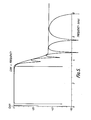
- Figure 5 shows a typical attenuation requirement for a decimator or interpolator for change between a 16kHz sampling rate and an l8kHz sampling rate.
- the requirement shown is for the 3dB point to be at approximately 3.5kHz.
- the approach to this design problem is to design a 'Prior Art' filter using APNs to meet the performance requirement assuming that the 3dB point is at 4kHz, ie. to keep the inner co-efficient K 2 of the nested all pass network at zero, and then to further optimise the filter, varying the inner co-efficient K 2 until the 3dB point is at the position required to meet the performance requirement.
- Figure 3 shows a decimator filter structure implemented using this approach.
- the input signal travels along two branch paths 21 and 23, each consisting of a cascade of all pass networks.
- Elements 3' to 13' comprise the nested all pass network 1' which operates at the higher of the two sampling frequencies F s , 2F S .
- Element 1 is the 'inner' all pass network filter, whose co-efficient K 2 is largely responsible for the position of the 3dB point.
- Element 25 is a single delay element which delays the output signal by one clock cycle at the higher of the two sample rates, rate 2F S .
- the next step is to subsample the signals travelling down the two branches 21, 23 of the filter by switches 27 and 29, and then pass the subsampled signals through further all pass networks 31, 33 and 35 which operate at the lower of the two sampling rates, rate F s .
- the outputs are summed at a summing node 37 and the amplitude of the final signal reduced by a factor 0.5.
- a number of changes can be made.
- the number of all pass networks in each branch of the filter structure can be changed, and the values of all the multiplier co-efficients can be changed, enabling design of the filter structure to meet a wide variety of frequency response requirements.
- FIG. 4 shows an Interpolator filter structure likewise implemented using the above approach.
- APN filters 41, 43 and 45 operate on the input signal at the lower of the two sampling rates.
- Switches 47 and 49 increase the sample rate by a factor of two by introducing additional samples. All the additional samples are set to zero.
- the signal on one 51 of the two branches 51, 53 of the filter structure is now passed through a delay element 55 and then a nested all pass network filter 1' which operates in an identical manner to the nested all pass network 1' described above.
- the outputs from the two branches of the filter structure are then summed together at a summing node 57 to give the final filtered, interpolated output.
Landscapes
- Physics & Mathematics (AREA)
- Engineering & Computer Science (AREA)
- Computer Hardware Design (AREA)
- Mathematical Physics (AREA)
- Transmission Systems Not Characterized By The Medium Used For Transmission (AREA)
- Complex Calculations (AREA)
- Filters That Use Time-Delay Elements (AREA)
- Gasification And Melting Of Waste (AREA)
- Networks Using Active Elements (AREA)
- Oscillators With Electromechanical Resonators (AREA)
- Digital Transmission Methods That Use Modulated Carrier Waves (AREA)
Applications Claiming Priority (2)
| Application Number | Priority Date | Filing Date | Title |
|---|---|---|---|
| GB8521376A GB2179815B (en) | 1985-08-28 | 1985-08-28 | Interpolator / decimator filter structure |
| GB8521376 | 1985-08-28 |
Publications (2)
| Publication Number | Publication Date |
|---|---|
| EP0212950A2 true EP0212950A2 (de) | 1987-03-04 |
| EP0212950A3 EP0212950A3 (de) | 1988-05-04 |
Family
ID=10584364
Family Applications (1)
| Application Number | Title | Priority Date | Filing Date |
|---|---|---|---|
| EP86306289A Withdrawn EP0212950A3 (de) | 1985-08-28 | 1986-08-14 | Interpolierende, bzw. dezimierende Filterstruktur und digitales Filter dafür |
Country Status (9)
| Country | Link |
|---|---|
| US (1) | US4864526A (de) |
| EP (1) | EP0212950A3 (de) |
| JP (1) | JPS6251821A (de) |
| CN (1) | CN1012547B (de) |
| BG (1) | BG46610A3 (de) |
| CA (1) | CA1269136A (de) |
| FI (1) | FI863446A7 (de) |
| GB (2) | GB2179815B (de) |
| IN (1) | IN167745B (de) |
Cited By (2)
| Publication number | Priority date | Publication date | Assignee | Title |
|---|---|---|---|---|
| GB2249176A (en) * | 1990-10-27 | 1992-04-29 | Atomic Energy Authority Uk | Shot detection |
| EP0620641A1 (de) * | 1993-04-16 | 1994-10-19 | France Telecom | Signalverarbeitungsanordnung mit mehreren verschiedenen Filtern, insbesondere für audiofrequente Codierung von Stimmensignalen |
Families Citing this family (9)
| Publication number | Priority date | Publication date | Assignee | Title |
|---|---|---|---|---|
| FR2638303B1 (fr) * | 1988-10-26 | 1991-01-18 | Texas Instruments France | Filtre interpolatif perfectionne |
| JP2517083B2 (ja) * | 1988-11-11 | 1996-07-24 | 松下電器産業株式会社 | 調理器用の蓋つまみ |
| JP2583610B2 (ja) * | 1989-07-07 | 1997-02-19 | 三菱電機株式会社 | A/d、d/a変換装置 |
| US5245667A (en) * | 1991-04-03 | 1993-09-14 | Frox, Inc. | Method and structure for synchronizing multiple, independently generated digital audio signals |
| CN1067818C (zh) * | 1998-01-22 | 2001-06-27 | 曹保定 | 可消除负阻尼的同步发电机励磁控制方法及调节器 |
| JP3349688B2 (ja) | 1999-11-05 | 2002-11-25 | 松下電器産業株式会社 | 移動体通信端末装置 |
| US7164741B2 (en) * | 2001-05-09 | 2007-01-16 | Signum Concept, Inc. | Non-recursive resampling digital fir filter structure for demodulating 3G cellular signals |
| US7158591B2 (en) * | 2001-05-09 | 2007-01-02 | Signum Concept, Inc. | Recursive resampling digital filter structure for demodulating 3G wireless signals |
| US8521798B2 (en) * | 2008-09-22 | 2013-08-27 | Magor Communications Corporation | Second order real allpass filter |
Family Cites Families (5)
| Publication number | Priority date | Publication date | Assignee | Title |
|---|---|---|---|---|
| US3855423A (en) * | 1973-05-03 | 1974-12-17 | Bell Telephone Labor Inc | Noise spectrum equalizer |
| US4270027A (en) * | 1979-11-28 | 1981-05-26 | International Telephone And Telegraph Corporation | Telephone subscriber line unit with sigma-delta digital to analog converter |
| US4302631A (en) * | 1979-11-28 | 1981-11-24 | International Telephone And Telegraph Corporation | Decimator apparatus for decreasing the word rate of a digital signal of the type employed in digital telephone systems |
| US4270026A (en) * | 1979-11-28 | 1981-05-26 | International Telephone And Telegraph Corporation | Interpolator apparatus for increasing the word rate of a digital signal of the type employed in digital telephone systems |
| JPS5952911A (ja) * | 1982-09-20 | 1984-03-27 | Nec Corp | トランスバ−サル・フイルタ |
-
1985
- 1985-08-28 GB GB8521376A patent/GB2179815B/en not_active Expired
-
1986
- 1986-07-18 IN IN561/MAS/86A patent/IN167745B/en unknown
- 1986-07-21 CA CA000514259A patent/CA1269136A/en not_active Expired - Fee Related
- 1986-08-08 US US06/894,996 patent/US4864526A/en not_active Expired - Fee Related
- 1986-08-14 EP EP86306289A patent/EP0212950A3/de not_active Withdrawn
- 1986-08-22 BG BG076253A patent/BG46610A3/xx unknown
- 1986-08-26 CN CN86105452.0A patent/CN1012547B/zh not_active Expired
- 1986-08-26 FI FI863446A patent/FI863446A7/fi not_active IP Right Cessation
- 1986-08-27 JP JP61201188A patent/JPS6251821A/ja active Pending
-
1989
- 1989-02-09 GB GB8902876A patent/GB2214021B/en not_active Expired - Lifetime
Non-Patent Citations (2)
| Title |
|---|
| IEE PROCEEDINGS, vol. 130, no. 6, December 1983, pages 225-234; R.A. VALENZUELA et al.: "Digital signal processing schemes for efficient interpolation and decimation" * |
| IEEE TRANSACTIONS ON CIRCUITS AND SYSTEMS; CAS-31, no. 11, November 1984; New York, US; S. CHU et al.: "Multirate filter designs using comb filters" * |
Cited By (4)
| Publication number | Priority date | Publication date | Assignee | Title |
|---|---|---|---|---|
| GB2249176A (en) * | 1990-10-27 | 1992-04-29 | Atomic Energy Authority Uk | Shot detection |
| EP0620641A1 (de) * | 1993-04-16 | 1994-10-19 | France Telecom | Signalverarbeitungsanordnung mit mehreren verschiedenen Filtern, insbesondere für audiofrequente Codierung von Stimmensignalen |
| FR2704110A1 (fr) * | 1993-04-16 | 1994-10-21 | Balestro Freddy | Dispositif de traitement de signaux utilisant plusieurs filtrages différents, notamment pour le codage audiofréquence de signaux vocaux. |
| US5555272A (en) * | 1993-04-16 | 1996-09-10 | France Telecom | Signal processing device using several different filterings, especially for audio-frequency coding of voice signals |
Also Published As
| Publication number | Publication date |
|---|---|
| FI863446A0 (fi) | 1986-08-26 |
| GB8521376D0 (en) | 1985-10-02 |
| GB8902876D0 (en) | 1989-03-30 |
| CA1269136A (en) | 1990-05-15 |
| EP0212950A3 (de) | 1988-05-04 |
| GB2179815B (en) | 1989-11-29 |
| FI863446A7 (fi) | 1987-03-01 |
| US4864526A (en) | 1989-09-05 |
| BG46610A3 (bg) | 1990-01-15 |
| GB2179815A (en) | 1987-03-11 |
| IN167745B (de) | 1990-12-15 |
| CN86105452A (zh) | 1987-05-27 |
| CN1012547B (zh) | 1991-05-01 |
| GB2214021A (en) | 1989-08-23 |
| JPS6251821A (ja) | 1987-03-06 |
| GB2214021B (en) | 1990-05-23 |
Similar Documents
| Publication | Publication Date | Title |
|---|---|---|
| Kwentus et al. | Application of filter sharpening to cascaded integrator-comb decimation filters | |
| Valenzuela et al. | Digital signal processing schemes for efficient interpolation and decimation | |
| Lim et al. | Frequency-response masking approach for digital filter design: Complexity reduction via masking filter factorization | |
| US4649507A (en) | Segmented transversal filter | |
| Johansson et al. | Linear-phase FIR interpolation, decimation, and mth-band filters utilizing the Farrow structure | |
| US4864526A (en) | Interpolator/decimator filter structure and a digital filter therefor | |
| Pun et al. | On the design and efficient implementation of the Farrow structure | |
| EP0693235B1 (de) | Dezimationsfilter | |
| EP1449298B1 (de) | Aufwartsabtaster-, abtastrateumsetzungs- und abtastfrequenzerniedrigungsstufen enthaltendes zeitdiskretes filter | |
| JP3223188B2 (ja) | 積の数を減らすことによりディジタルフィルタバンクの電力消費を減らす方法 | |
| US4908787A (en) | Interpolator/decimator filter structure and a notch filter therefor | |
| Babic et al. | Decimation by irrational factor using CIC filter and linear interpolation | |
| Djokic et al. | A new improvement to the Powell and Chau linear phase IIR filters | |
| JPH0983299A (ja) | 櫛型フィルタとそれを用いた送受信装置 | |
| Russell | Efficient rational sampling rate alteration using IIR filters | |
| CA1276988C (en) | Interpolator/decimator filter structure and a digital filter therefor | |
| US4101853A (en) | Frequency sampling filter | |
| GB2180114A (en) | Digital filters | |
| Martins et al. | Cascade switched-capacitor IIR decimating filters | |
| CA1269723A (en) | Notch filter for an interpolator/decimator filter structure | |
| Saramaki et al. | A novel systematic approach for synthesizing multiplication-free highly-selective FIR half-band decimators and interpolators | |
| US4633225A (en) | Impedance line matching device using feedback | |
| Dolecek | Modified CIC filter for rational sample rate conversion | |
| EP0214776A2 (de) | Niederfrequentes digitales Lochfilter | |
| Ang et al. | Virtex FPGA implementation of a polyphase filter for sample rate conversion |
Legal Events
| Date | Code | Title | Description |
|---|---|---|---|
| PUAI | Public reference made under article 153(3) epc to a published international application that has entered the european phase |
Free format text: ORIGINAL CODE: 0009012 |
|
| AK | Designated contracting states |
Kind code of ref document: A2 Designated state(s): DE FR IT NL SE |
|
| PUAL | Search report despatched |
Free format text: ORIGINAL CODE: 0009013 |
|
| AK | Designated contracting states |
Kind code of ref document: A3 Designated state(s): DE FR IT NL SE |
|
| 17P | Request for examination filed |
Effective date: 19881007 |
|
| 17Q | First examination report despatched |
Effective date: 19910213 |
|
| STAA | Information on the status of an ep patent application or granted ep patent |
Free format text: STATUS: THE APPLICATION IS DEEMED TO BE WITHDRAWN |
|
| 18D | Application deemed to be withdrawn |
Effective date: 19910625 |
|
| RIN1 | Information on inventor provided before grant (corrected) |
Inventor name: DYER, NIGEL PAUL |