EP0212727B1 - Optical weft stop motion for looms with a u-shaped reed - Google Patents
Optical weft stop motion for looms with a u-shaped reed Download PDFInfo
- Publication number
- EP0212727B1 EP0212727B1 EP86201339A EP86201339A EP0212727B1 EP 0212727 B1 EP0212727 B1 EP 0212727B1 EP 86201339 A EP86201339 A EP 86201339A EP 86201339 A EP86201339 A EP 86201339A EP 0212727 B1 EP0212727 B1 EP 0212727B1
- Authority
- EP
- European Patent Office
- Prior art keywords
- optical
- stop motion
- weft stop
- motion according
- optically conductive
- Prior art date
- Legal status (The legal status is an assumption and is not a legal conclusion. Google has not performed a legal analysis and makes no representation as to the accuracy of the status listed.)
- Expired
Links
- 230000003287 optical effect Effects 0.000 title claims description 50
- 235000014676 Phragmites communis Nutrition 0.000 title claims description 20
- 229910052751 metal Inorganic materials 0.000 claims description 5
- 239000002184 metal Substances 0.000 claims description 5
- 239000000463 material Substances 0.000 claims description 3
- 239000004411 aluminium Substances 0.000 claims description 2
- 229910052782 aluminium Inorganic materials 0.000 claims description 2
- XAGFODPZIPBFFR-UHFFFAOYSA-N aluminium Chemical compound [Al] XAGFODPZIPBFFR-UHFFFAOYSA-N 0.000 claims description 2
- 238000005304 joining Methods 0.000 claims description 2
- 239000004417 polycarbonate Substances 0.000 claims description 2
- 229920000515 polycarbonate Polymers 0.000 claims description 2
- 239000011358 absorbing material Substances 0.000 claims 1
- 238000009825 accumulation Methods 0.000 description 2
- 239000000428 dust Substances 0.000 description 2
- 230000002745 absorbent Effects 0.000 description 1
- 239000002250 absorbent Substances 0.000 description 1
- 230000005540 biological transmission Effects 0.000 description 1
- 238000004040 coloring Methods 0.000 description 1
- 238000001514 detection method Methods 0.000 description 1
- 239000011521 glass Substances 0.000 description 1
- 230000010354 integration Effects 0.000 description 1
- 238000004519 manufacturing process Methods 0.000 description 1
- 238000000034 method Methods 0.000 description 1
- 229920003023 plastic Polymers 0.000 description 1
- 238000001771 vacuum deposition Methods 0.000 description 1
Images

Classifications
-
- D—TEXTILES; PAPER
- D03—WEAVING
- D03D—WOVEN FABRICS; METHODS OF WEAVING; LOOMS
- D03D51/00—Driving, starting, or stopping arrangements; Automatic stop motions
- D03D51/18—Automatic stop motions
- D03D51/34—Weft stop motions
-
- D—TEXTILES; PAPER
- D03—WEAVING
- D03D—WOVEN FABRICS; METHODS OF WEAVING; LOOMS
- D03D47/00—Looms in which bulk supply of weft does not pass through shed, e.g. shuttleless looms, gripper shuttle looms, dummy shuttle looms
- D03D47/27—Drive or guide mechanisms for weft inserting
- D03D47/277—Guide mechanisms
- D03D47/278—Guide mechanisms for pneumatic looms
Definitions
- This invention relates to an optical weft stop motion for looms with a U-shaped reed, in other words a detection element to determine if the shoot extends completely or not through the shed of the loom.
- a known arrangement of this type is described in the European patent application no. 109.929 and consists mainly of one optical emitter, one optical receiver and at least one reflector, whereby it is provided that the light beam between emitter and receiver crosses the recess in the U-shaped reed.
- the reflectors and the emitter and the receiver according to the known designs do not have a compact design it is obvious that deviations are easily originated in the reflection of the light signal between the emitter and the receiver.
- the passage of light is hampered by the thickness of the reed lamellae, the closeness and the oblique position of the lamellae.
- the main disadvantage of the said design consists in the fact that by the use of two prismatic elements corners and clearances are created between, on the one side, these elements and, on the other side, the adjacent reed lamellae, in which dust accumulation may arise which may cause a wrong indication of the optical weft stop motion.
- the present invention provides an optical weft stop motion which is very effective and reliable.
- the invention relates to an optical weft stop motion for looms with a U-shaped reed, which consists in the combination of one optical emitter, one optical receiver, and optically conductive means attachable between the reed lamellae, whereby these optically conductive means are provided with light reflecting side walls which first reflect the light from the emitter into a parallel beam whose width corresponds or substantially corresponds with the depth of the U-shaped recess of the reed and then reflect it further to the receiver, characterised in that the optically conductive means consist in one optically conductive plate provided with a recess which is congruent or almost congruent with and adjacent to the recess in the U-shaped reed. A number of light absorbing side walls can be provided which exclude a wrong incidence of light.
- the invention mainly consists in the combination of one optical emitter 1, one optical receiver 2 and one optically conductive plate 3.
- the optical emitter 1 is formed by a point light source, e.g. a light emitting diode.
- the optical receiver 2 consists of an arbitrary light sensitive electronic element. Naturally, the emitter 1 as well as the receiver 2 are connected by means of appropriate optical or electronic connections to on the one side a power supply and on the other side to a signal processing unit.
- the optically conductive plate 3 is made from transparent plastic or possibly glass. It is preferred to use a strip of polycarbonate with a thickness of 0.2 to 0.35 mm.
- the optically conductive plate 3 is provided with a metal lining plate, respectively 4 and 5, made from any possible material, in one shape or another so that the total thickness of the optical detector is in accordance with the mutual distance between two adjacent reed lamellae 6 and 7.
- the optically conductive plate 3, aa well as the metal lining plates 4 and 5 are provided with a recess 8 which is congruent or almost congruent with and adjacent to the recesses 9 which form the tunnel of the U-shaped reed.
- the optically conductive plate 3 is provided with reflecting side walls 10 and 11, in one shape or another so that the light beams 12, which are emitted by the optical emitter 1 are reflected in the form of a bundle through almost the complete cross section of the recess 8 and eventually are received by the receiver 2.
- the reflections along the side walls 10 and 11 may be of a prismatic nature. However, it is preferred that said side walls 10 and 11 are coated with a light reflecting material. For this purpose e.g. the side walls 10 and 11 are polished and then e.g. provided with a metal layer by means of vacuum deposition, e.g. aluminium.
- the side walls 10 and 11 naturally are executed according to the invention in such a manner that, on the one side, always a parallel light beam 13 is obtained in the recess 8 by reflection in the side wall 10 and on the other side, said light beam 13 is reflected completely by the side wall 11 to the optical detector 2. For that reason in the embodiment of figure 1 the side walls 10 and 11 are made parabolic.
- the internal corners 14 and 15 of the recesses 8 and 9 are, like in the most practical embodiments, provided with roundings, in such a manner that also the form of the reflecting side walls 10 and 11 are adapted to such a degree that the light beam remains almost parallel over the complete cross section of the recess 8 in the optically conductive plate 3.
- the side walls 10 and 11 have shapes with parabolic portions 16 and portions 17 deviating from that.
- the shape of portions 17 is adapted in such a manner that also the light rays which are refracted by the roundings in the internal corners 14 and 15, show such a path that, on the one side they form part of the parallel light beam 13, and, on the other side, are reflected to the optical detector 2.
- one or more side walls 18 to 21 are dulled or painted black. Also the side walls which are adjacent to the lining plates 4 and 5 may, for the same reason, be dulled or painted black partly or completely.
- the bridge 22, respectively between the portion of the plate 3 which is adjacent to the emitter 1 and the portion which is adjacent to the receiver 2 is made light absorbent, e.g. by colouring it.
- the inner faces 25 and 26 are preferably painted black.
- the optically conductive plate 3 is also provided with connecting faces 27 and 28 on which respectively the optical emitter 1 and the optical receiver 2 are mounted. This may be realized e.g. by mounting at first the optical emitter 1 and the receiver 2 on a supporting plate 29 with a great position accuracy, e.g. by means of techniques as employed by the fabrication of chips. Further, the supporting plate 29 with the emitter 1 and the receiver 2 is glued against the joining faces 27 and 28. Naturally, the metal lining plates 4 may provide the further necessary stiffening.
Landscapes
- Engineering & Computer Science (AREA)
- Textile Engineering (AREA)
- Looms (AREA)
- Woven Fabrics (AREA)
- Organic Low-Molecular-Weight Compounds And Preparation Thereof (AREA)
- Crystals, And After-Treatments Of Crystals (AREA)
Description
- This invention relates to an optical weft stop motion for looms with a U-shaped reed, in other words a detection element to determine if the shoot extends completely or not through the shed of the loom.
- In particular it relates to an optical weft stop motion of the type by which the light of an optical emitter crosses the complete or almost the complete cross section of the tunnel in the U-shaped reed.
- A known arrangement of this type is described in the European patent application no. 109.929 and consists mainly of one optical emitter, one optical receiver and at least one reflector, whereby it is provided that the light beam between emitter and receiver crosses the recess in the U-shaped reed. As the reflectors and the emitter and the receiver according to the known designs do not have a compact design it is obvious that deviations are easily originated in the reflection of the light signal between the emitter and the receiver. Moreover with such a design the passage of light is hampered by the thickness of the reed lamellae, the closeness and the oblique position of the lamellae.
- A better solution to reflect the transmitted light beam according to a well-defined path is given by the design according to the European patent application no. 137.380, whereby one is mainly working with two prismatic elements which are put between two adjacent reed lamellae, respectively above and underneath the recesses in the U-shaped reed. However, it is obvious that both prismatic bodies have to be oriented perfectly parallel to each other to obtain the desired reflection of the emitted light signal. So, such an arrangement has the disadvantage that deviations in the path of the light beam may occur easily.
- The main disadvantage of the said design consists in the fact that by the use of two prismatic elements corners and clearances are created between, on the one side, these elements and, on the other side, the adjacent reed lamellae, in which dust accumulation may arise which may cause a wrong indication of the optical weft stop motion. In order to provide a solution for said and other disadvantages the present invention provides an optical weft stop motion which is very effective and reliable.
- For this purpose the invention relates to an optical weft stop motion for looms with a U-shaped reed, which consists in the combination of one optical emitter, one optical receiver, and optically conductive means attachable between the reed lamellae, whereby these optically conductive means are provided with light reflecting side walls which first reflect the light from the emitter into a parallel beam whose width corresponds or substantially corresponds with the depth of the U-shaped recess of the reed and then reflect it further to the receiver, characterised in that the optically conductive means consist in one optically conductive plate provided with a recess which is congruent or almost congruent with and adjacent to the recess in the U-shaped reed. A number of light absorbing side walls can be provided which exclude a wrong incidence of light.
- In view of a better demonstration of the characteristics according to the invention, hereafter, as examples without any restrictive character, some preferred embodiments are described referring to the accompanying drawings, wherein:
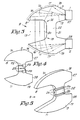
- figure 1 shows an embodiment of the optical weft stop motion on a large scale;
- figure 2 shows a cross section according to line 11-11 in figure 1;
- figure 3 lines out and shows on a very large scale the path of the light beam in a possible embodiment of an optical conductive plate;
- figures 4 and 5 show two variants of the optical conductive plate with respect to the limitation of undersired light passages.
- As shown in the figures the invention mainly consists in the combination of one optical emitter 1, one
optical receiver 2 and one opticallyconductive plate 3. - The optical emitter 1 is formed by a point light source, e.g. a light emitting diode. The
optical receiver 2 consists of an arbitrary light sensitive electronic element. Naturally, the emitter 1 as well as thereceiver 2 are connected by means of appropriate optical or electronic connections to on the one side a power supply and on the other side to a signal processing unit. - The optically
conductive plate 3 is made from transparent plastic or possibly glass. It is preferred to use a strip of polycarbonate with a thickness of 0.2 to 0.35 mm. - As shown in figure 2, for preference the optically
conductive plate 3 is provided with a metal lining plate, respectively 4 and 5, made from any possible material, in one shape or another so that the total thickness of the optical detector is in accordance with the mutual distance between two adjacent reed lamellae 6 and 7. - In orderto make a dust accumulation impossible between the reed lamellae 6 and 7 close to the optical detector, the optically
conductive plate 3, aa well as themetal lining plates 4 and 5, are provided with arecess 8 which is congruent or almost congruent with and adjacent to therecesses 9 which form the tunnel of the U-shaped reed. - Further, the optically
conductive plate 3 is provided with reflectingside walls recess 8 and eventually are received by thereceiver 2. - The reflections along the
side walls side walls side walls - As the
recess 8 according to the invention is congruent or almost congruent with therecesses 9 in the reed lamellae 6 and 7, theside walls parallel light beam 13 is obtained in therecess 8 by reflection in theside wall 10 and on the other side, saidlight beam 13 is reflected completely by theside wall 11 to theoptical detector 2. For that reason in the embodiment of figure 1 theside walls - As shown in figure 3, the
internal corners recesses side walls recess 8 in the opticallyconductive plate 3. For this purpose theside walls parabolic portions 16 andportions 17 deviating from that. The shape ofportions 17 is adapted in such a manner that also the light rays which are refracted by the roundings in theinternal corners parallel light beam 13, and, on the other side, are reflected to theoptical detector 2. - In order to avoid a wrong light reflection in the optically
conductive plate 3 it is preferred that one ormore side walls 18 to 21 are dulled or painted black. Also the side walls which are adjacent to thelining plates 4 and 5 may, for the same reason, be dulled or painted black partly or completely. In order to avoid a direct light transmission in the opticallyconductive plate 3 from the optical emitter 1 to theoptical receiver 2, it is preferred that thebridge 22, respectively between the portion of theplate 3 which is adjacent to the emitter 1 and the portion which is adjacent to thereceiver 2, is made light absorbent, e.g. by colouring it. According to variants which are represented in figures 4 and 5 one may also providerecesses 23 orgrooves 24 to limit the direct passage of light. Theinner faces - The optically
conductive plate 3 is also provided with connectingfaces optical receiver 2 are mounted. This may be realized e.g. by mounting at first the optical emitter 1 and thereceiver 2 on a supportingplate 29 with a great position accuracy, e.g. by means of techniques as employed by the fabrication of chips. Further, the supportingplate 29 with the emitter 1 and thereceiver 2 is glued against the joiningfaces metal lining plates 4 may provide the further necessary stiffening. - According to a variant, one may provide the integration of a pre-amplifier or a power supply for the emitter 1 by mounting the emitter 1 and the
receiver 2 on the supportingplate 29. - The operation of the optical weft stop motion is easily deduced from the drawings. If a
weftthread 30 comes between therecess 8 and theplate 3, a portion of the light beam is interrupted whereby the incidence of light on theoptical receiver 2 is reduced, which is electronically interpreted as the arrival of theweft thread 30.
Claims (13)
Applications Claiming Priority (2)
| Application Number | Priority Date | Filing Date | Title |
|---|---|---|---|
| BE2060769 | 1985-08-26 | ||
| BE2/60769A BE903115A (en) | 1985-08-26 | 1985-08-26 | OPTICAL IMPACT GUARD FOR WEAVING MACHINES WITH A U-SHAPED REED |
Publications (2)
| Publication Number | Publication Date |
|---|---|
| EP0212727A1 EP0212727A1 (en) | 1987-03-04 |
| EP0212727B1 true EP0212727B1 (en) | 1989-05-03 |
Family
ID=3865766
Family Applications (1)
| Application Number | Title | Priority Date | Filing Date |
|---|---|---|---|
| EP86201339A Expired EP0212727B1 (en) | 1985-08-26 | 1986-07-30 | Optical weft stop motion for looms with a u-shaped reed |
Country Status (4)
| Country | Link |
|---|---|
| US (1) | US4716942A (en) |
| EP (1) | EP0212727B1 (en) |
| BE (1) | BE903115A (en) |
| DE (1) | DE3663158D1 (en) |
Families Citing this family (17)
| Publication number | Priority date | Publication date | Assignee | Title |
|---|---|---|---|---|
| EP0286590B1 (en) * | 1987-04-08 | 1991-05-08 | GebràDer Sulzer Aktiengesellschaft | Weft yarn storage device for a loom |
| EP0290706B1 (en) * | 1987-05-14 | 1990-07-25 | Istituto Nazionale Di Ottica | A device for the control of the weft yarn in the looms operated by compressed air |
| DE3921402A1 (en) * | 1989-06-29 | 1991-01-24 | Kunststoff Verarbeitung Gmbh D | LIGHT ELECTRIC MEASURING HEAD FOR MONITORING AN EXTRUDED PLASTIC PROFILE |
| WO1991010898A1 (en) * | 1990-01-12 | 1991-07-25 | Rhone-Poulenc Viscosuisse Sa | Device for photo-electrically monitoring a moving yarn |
| DE4142356A1 (en) * | 1990-12-28 | 1992-07-02 | Nissan Motor | WOMB MONITORING SYSTEM FOR A WEAVING MACHINE |
| SE469597B (en) * | 1991-09-23 | 1993-08-02 | Rydborn S A O | DEVICE FOR MONITORING THE IMAGE IN A WEAVING CHAIR, INCLUDING DIRECTLY LIGHT SENSITIVE ELEMENTS |
| SE469448B (en) * | 1991-09-27 | 1993-07-05 | Rydborn S A O | OPTICAL MONITORING DEVICE TO DETECT A TRADE |
| GB9204413D0 (en) * | 1992-02-29 | 1992-04-15 | Northern Eng Ind | Method and apparatus for observing of gap between relatively rotating parts |
| IT1257196B (en) * | 1992-05-26 | 1996-01-10 | DEVICE FOR THE CONTINUOUS CONTROL OF THE STRUCTURE AND INTEGRITY OF THE NEEDLES DURING THE OPERATION OF A KNITTING MACHINE. | |
| BE1006073A3 (en) * | 1992-07-03 | 1994-05-03 | Picanol Nv | Impact guard for looms. |
| JP2609048B2 (en) * | 1993-07-12 | 1997-05-14 | 沖電気工業株式会社 | Carrier detection device |
| BE1010779A3 (en) * | 1996-12-02 | 1999-01-05 | Picanol N V Naamloze Vennoosch | WOOF WACHTER for a weaving machine. |
| US11412900B2 (en) | 2016-04-11 | 2022-08-16 | Gpcp Ip Holdings Llc | Sheet product dispenser with motor operation sensing |
| US11395566B2 (en) | 2016-04-11 | 2022-07-26 | Gpcp Ip Holdings Llc | Sheet product dispenser |
| JP6776980B2 (en) * | 2017-03-29 | 2020-10-28 | 株式会社豊田自動織機 | Weft detector for air jet loom |
| EP3748285A1 (en) * | 2019-06-06 | 2020-12-09 | Gebrüder Loepfe AG | Optical sensor for measuring a property of an elongate textile body with reduced sensitivity to environmental light |
| EP3748342B1 (en) * | 2019-06-06 | 2023-05-03 | Gebrüder Loepfe AG | Optical sensor for measuring a property of an elongate textile body in a uniform optical field |
Family Cites Families (10)
| Publication number | Priority date | Publication date | Assignee | Title |
|---|---|---|---|---|
| DE1785035B2 (en) * | 1968-08-02 | 1973-01-11 | Sick, Erwin, 8000 München | DEVICE FOR MONITORING THE WEFT THREAD IN SHUTTERLESS LOOMS |
| FR2125156A1 (en) * | 1971-02-15 | 1972-09-29 | Elitex Zavody Textilniho | Weft thread detector - fitted to air jet shuttless looms |
| NL7206368A (en) * | 1972-05-10 | 1973-11-13 | ||
| CH589738A5 (en) * | 1975-03-21 | 1977-07-15 | Sulzer Ag | |
| JPS6328225Y2 (en) * | 1980-03-15 | 1988-07-29 | ||
| CH646470A5 (en) * | 1980-09-05 | 1984-11-30 | Rueti Ag Maschf | Jet weaving machine. |
| GB2090619A (en) * | 1981-01-07 | 1982-07-14 | Leesona Corp | Means and method for sensing loom conditions |
| CH659672A5 (en) * | 1982-11-11 | 1987-02-13 | Loepfe Ag Geb | Weft thread monitor. |
| JPS59163448A (en) * | 1983-03-09 | 1984-09-14 | 日産自動車株式会社 | Weft yarn detector of air jet type loom |
| IT1171736B (en) * | 1983-10-10 | 1987-06-10 | Roy Electrotex Spa | OPTICAL WEFT DETECTOR FOR AIR-JET WEAVING FRAMES |
-
1985
- 1985-08-26 BE BE2/60769A patent/BE903115A/en not_active IP Right Cessation
-
1986
- 1986-07-30 DE DE8686201339T patent/DE3663158D1/en not_active Expired
- 1986-07-30 EP EP86201339A patent/EP0212727B1/en not_active Expired
- 1986-08-19 US US06/898,044 patent/US4716942A/en not_active Expired - Fee Related
Also Published As
| Publication number | Publication date |
|---|---|
| BE903115A (en) | 1986-02-26 |
| EP0212727A1 (en) | 1987-03-04 |
| US4716942A (en) | 1988-01-05 |
| DE3663158D1 (en) | 1989-06-08 |
Similar Documents
| Publication | Publication Date | Title |
|---|---|---|
| US4716942A (en) | Optical weft stop motion for looms with a U-shaped reed | |
| EP0006361B1 (en) | An illuminated indicator gauge | |
| CZ302798B6 (en) | Compact moisture sensor with efficient high obliquity optics | |
| US4561722A (en) | Beam divider | |
| JPS595980A (en) | Photoelectric detector | |
| US6409368B1 (en) | Lighting device for vehicles | |
| JP2513348B2 (en) | Lighting equipment | |
| DE3269905D1 (en) | Reflection light barrier with an extended detection range | |
| US20200381574A1 (en) | Optical sensing chip packaging structure | |
| CA2228335A1 (en) | Photodetector with coated reflector | |
| NO334674B1 (en) | Optical rangefinder | |
| JPH01143368A (en) | Led display element | |
| JP4014670B2 (en) | Optical sensor | |
| US3571602A (en) | Optical system to reduce reflection losses in a photocell | |
| JP2006135057A (en) | Optical sensor | |
| KR20030044822A (en) | Light guiding plate for front light | |
| JPS6219963Y2 (en) | ||
| JPH1136739A (en) | Daylighting board | |
| JP2954953B2 (en) | Loom weft feeler | |
| JPS6112601Y2 (en) | ||
| JPH0143922B2 (en) | ||
| KR940001142B1 (en) | Object detection device using light reflectance spectrum of port diode. | |
| KR20250123084A (en) | Light projecting device module | |
| JP2764753B2 (en) | Loom weft feeler | |
| JPS6285479A (en) | Semiconductor composite photo receiving and emitting device |
Legal Events
| Date | Code | Title | Description |
|---|---|---|---|
| PUAI | Public reference made under article 153(3) epc to a published international application that has entered the european phase |
Free format text: ORIGINAL CODE: 0009012 |
|
| AK | Designated contracting states |
Kind code of ref document: A1 Designated state(s): CH DE FR GB IT LI NL |
|
| 17P | Request for examination filed |
Effective date: 19870305 |
|
| 17Q | First examination report despatched |
Effective date: 19880316 |
|
| RAP1 | Party data changed (applicant data changed or rights of an application transferred) |
Owner name: PICANOL N.V. |
|
| GRAA | (expected) grant |
Free format text: ORIGINAL CODE: 0009210 |
|
| AK | Designated contracting states |
Kind code of ref document: B1 Designated state(s): CH DE FR GB IT LI NL |
|
| REF | Corresponds to: |
Ref document number: 3663158 Country of ref document: DE Date of ref document: 19890608 |
|
| ITF | It: translation for a ep patent filed | ||
| ET | Fr: translation filed | ||
| PLBE | No opposition filed within time limit |
Free format text: ORIGINAL CODE: 0009261 |
|
| STAA | Information on the status of an ep patent application or granted ep patent |
Free format text: STATUS: NO OPPOSITION FILED WITHIN TIME LIMIT |
|
| 26N | No opposition filed | ||
| GBPC | Gb: european patent ceased through non-payment of renewal fee | ||
| GBDL | Gb: delete "european patent ceased" from journal |
Free format text: 5324, PAGE 1424 |
|
| PGFP | Annual fee paid to national office [announced via postgrant information from national office to epo] |
Ref country code: GB Payment date: 19910729 Year of fee payment: 6 |
|
| ITTA | It: last paid annual fee | ||
| PG25 | Lapsed in a contracting state [announced via postgrant information from national office to epo] |
Ref country code: GB Effective date: 19920730 |
|
| GBPC | Gb: european patent ceased through non-payment of renewal fee |
Effective date: 19920730 |
|
| PGFP | Annual fee paid to national office [announced via postgrant information from national office to epo] |
Ref country code: FR Payment date: 19930618 Year of fee payment: 8 |
|
| PGFP | Annual fee paid to national office [announced via postgrant information from national office to epo] |
Ref country code: CH Payment date: 19930624 Year of fee payment: 8 |
|
| PGFP | Annual fee paid to national office [announced via postgrant information from national office to epo] |
Ref country code: DE Payment date: 19930730 Year of fee payment: 8 |
|
| PGFP | Annual fee paid to national office [announced via postgrant information from national office to epo] |
Ref country code: NL Payment date: 19930731 Year of fee payment: 8 |
|
| PG25 | Lapsed in a contracting state [announced via postgrant information from national office to epo] |
Ref country code: LI Effective date: 19940731 Ref country code: CH Effective date: 19940731 |
|
| PG25 | Lapsed in a contracting state [announced via postgrant information from national office to epo] |
Ref country code: NL Effective date: 19950201 |
|
| NLV4 | Nl: lapsed or anulled due to non-payment of the annual fee | ||
| PG25 | Lapsed in a contracting state [announced via postgrant information from national office to epo] |
Ref country code: FR Effective date: 19950331 |
|
| REG | Reference to a national code |
Ref country code: CH Ref legal event code: PL |
|
| PG25 | Lapsed in a contracting state [announced via postgrant information from national office to epo] |
Ref country code: DE Effective date: 19950401 |
|
| REG | Reference to a national code |
Ref country code: FR Ref legal event code: ST |
|
| PG25 | Lapsed in a contracting state [announced via postgrant information from national office to epo] |
Ref country code: IT Free format text: LAPSE BECAUSE OF NON-PAYMENT OF DUE FEES;WARNING: LAPSES OF ITALIAN PATENTS WITH EFFECTIVE DATE BEFORE 2007 MAY HAVE OCCURRED AT ANY TIME BEFORE 2007. THE CORRECT EFFECTIVE DATE MAY BE DIFFERENT FROM THE ONE RECORDED. Effective date: 20050730 |