EP0212291A2 - Unter Wasser rotierender Wärmetauscherreaktor - Google Patents
Unter Wasser rotierender Wärmetauscherreaktor Download PDFInfo
- Publication number
- EP0212291A2 EP0212291A2 EP86110021A EP86110021A EP0212291A2 EP 0212291 A2 EP0212291 A2 EP 0212291A2 EP 86110021 A EP86110021 A EP 86110021A EP 86110021 A EP86110021 A EP 86110021A EP 0212291 A2 EP0212291 A2 EP 0212291A2
- Authority
- EP
- European Patent Office
- Prior art keywords
- heat transfer
- evaporator
- liquid
- transfer tubes
- module
- Prior art date
- Legal status (The legal status is an assumption and is not a legal conclusion. Google has not performed a legal analysis and makes no representation as to the accuracy of the status listed.)
- Withdrawn
Links
- 238000012546 transfer Methods 0.000 claims abstract description 46
- 239000007788 liquid Substances 0.000 claims abstract description 45
- 238000010438 heat treatment Methods 0.000 claims abstract description 32
- 238000000034 method Methods 0.000 claims abstract description 19
- 239000007795 chemical reaction product Substances 0.000 claims description 9
- 239000000047 product Substances 0.000 claims description 9
- 239000000126 substance Substances 0.000 claims description 9
- 238000001704 evaporation Methods 0.000 claims description 8
- 238000005338 heat storage Methods 0.000 claims description 8
- 238000003860 storage Methods 0.000 claims description 8
- 239000010409 thin film Substances 0.000 claims description 8
- 239000007787 solid Substances 0.000 claims description 7
- 239000000376 reactant Substances 0.000 claims description 4
- 238000004891 communication Methods 0.000 claims description 3
- 238000009826 distribution Methods 0.000 claims 7
- 230000001939 inductive effect Effects 0.000 claims 2
- 238000009827 uniform distribution Methods 0.000 claims 1
- 238000006243 chemical reaction Methods 0.000 abstract description 18
- 239000012530 fluid Substances 0.000 abstract description 8
- 230000008016 vaporization Effects 0.000 abstract description 2
- 230000001105 regulatory effect Effects 0.000 abstract 1
- XLYOFNOQVPJJNP-UHFFFAOYSA-N water Substances O XLYOFNOQVPJJNP-UHFFFAOYSA-N 0.000 description 22
- 230000008569 process Effects 0.000 description 16
- 150000003839 salts Chemical class 0.000 description 14
- 230000000694 effects Effects 0.000 description 12
- VNWKTOKETHGBQD-UHFFFAOYSA-N methane Chemical compound C VNWKTOKETHGBQD-UHFFFAOYSA-N 0.000 description 12
- 239000002918 waste heat Substances 0.000 description 12
- 239000012141 concentrate Substances 0.000 description 9
- 239000002826 coolant Substances 0.000 description 8
- 238000002156 mixing Methods 0.000 description 8
- 238000010276 construction Methods 0.000 description 7
- CURLTUGMZLYLDI-UHFFFAOYSA-N Carbon dioxide Chemical compound O=C=O CURLTUGMZLYLDI-UHFFFAOYSA-N 0.000 description 6
- 238000009835 boiling Methods 0.000 description 6
- 230000008020 evaporation Effects 0.000 description 6
- 239000011552 falling film Substances 0.000 description 6
- 238000001816 cooling Methods 0.000 description 5
- 238000004821 distillation Methods 0.000 description 5
- 235000015097 nutrients Nutrition 0.000 description 5
- 239000002253 acid Substances 0.000 description 4
- 238000013019 agitation Methods 0.000 description 4
- 230000008901 benefit Effects 0.000 description 4
- 238000011010 flushing procedure Methods 0.000 description 4
- 239000003295 industrial effluent Substances 0.000 description 4
- 238000007689 inspection Methods 0.000 description 4
- 238000011084 recovery Methods 0.000 description 4
- 238000000926 separation method Methods 0.000 description 4
- 241000894006 Bacteria Species 0.000 description 3
- 229910002092 carbon dioxide Inorganic materials 0.000 description 3
- 239000001569 carbon dioxide Substances 0.000 description 3
- 238000011109 contamination Methods 0.000 description 3
- 239000010408 film Substances 0.000 description 3
- 239000011521 glass Substances 0.000 description 3
- 230000000737 periodic effect Effects 0.000 description 3
- 238000005086 pumping Methods 0.000 description 3
- 230000008439 repair process Effects 0.000 description 3
- 239000012266 salt solution Substances 0.000 description 3
- 239000002351 wastewater Substances 0.000 description 3
- 150000007513 acids Chemical class 0.000 description 2
- 230000009471 action Effects 0.000 description 2
- 238000005273 aeration Methods 0.000 description 2
- 230000033228 biological regulation Effects 0.000 description 2
- 238000004140 cleaning Methods 0.000 description 2
- 230000006835 compression Effects 0.000 description 2
- 238000007906 compression Methods 0.000 description 2
- 238000005260 corrosion Methods 0.000 description 2
- 230000007797 corrosion Effects 0.000 description 2
- 238000010612 desalination reaction Methods 0.000 description 2
- 238000013461 design Methods 0.000 description 2
- 238000005187 foaming Methods 0.000 description 2
- 239000007789 gas Substances 0.000 description 2
- 239000013529 heat transfer fluid Substances 0.000 description 2
- 238000004519 manufacturing process Methods 0.000 description 2
- 239000000463 material Substances 0.000 description 2
- 239000012528 membrane Substances 0.000 description 2
- 238000012986 modification Methods 0.000 description 2
- 230000004048 modification Effects 0.000 description 2
- 239000011369 resultant mixture Substances 0.000 description 2
- 238000013341 scale-up Methods 0.000 description 2
- 239000013535 sea water Substances 0.000 description 2
- 239000010935 stainless steel Substances 0.000 description 2
- 229910001220 stainless steel Inorganic materials 0.000 description 2
- 239000004809 Teflon Substances 0.000 description 1
- 229920006362 Teflon® Polymers 0.000 description 1
- 238000013459 approach Methods 0.000 description 1
- QVGXLLKOCUKJST-UHFFFAOYSA-N atomic oxygen Chemical compound [O] QVGXLLKOCUKJST-UHFFFAOYSA-N 0.000 description 1
- 230000009286 beneficial effect Effects 0.000 description 1
- 230000031018 biological processes and functions Effects 0.000 description 1
- 230000015572 biosynthetic process Effects 0.000 description 1
- 239000005388 borosilicate glass Substances 0.000 description 1
- 238000009833 condensation Methods 0.000 description 1
- 230000005494 condensation Effects 0.000 description 1
- 238000007796 conventional method Methods 0.000 description 1
- 230000008878 coupling Effects 0.000 description 1
- 238000010168 coupling process Methods 0.000 description 1
- 238000005859 coupling reaction Methods 0.000 description 1
- 238000012864 cross contamination Methods 0.000 description 1
- 230000001419 dependent effect Effects 0.000 description 1
- 238000010790 dilution Methods 0.000 description 1
- 239000012895 dilution Substances 0.000 description 1
- 239000003651 drinking water Substances 0.000 description 1
- 235000020188 drinking water Nutrition 0.000 description 1
- 230000005611 electricity Effects 0.000 description 1
- 230000003028 elevating effect Effects 0.000 description 1
- 238000005516 engineering process Methods 0.000 description 1
- 230000002349 favourable effect Effects 0.000 description 1
- 238000011049 filling Methods 0.000 description 1
- 238000007701 flash-distillation Methods 0.000 description 1
- 238000007667 floating Methods 0.000 description 1
- 239000013505 freshwater Substances 0.000 description 1
- 230000012010 growth Effects 0.000 description 1
- 239000012535 impurity Substances 0.000 description 1
- 238000011065 in-situ storage Methods 0.000 description 1
- 230000002401 inhibitory effect Effects 0.000 description 1
- 230000003993 interaction Effects 0.000 description 1
- 239000003621 irrigation water Substances 0.000 description 1
- 230000033001 locomotion Effects 0.000 description 1
- 238000012423 maintenance Methods 0.000 description 1
- 230000004060 metabolic process Effects 0.000 description 1
- 229910001092 metal group alloy Inorganic materials 0.000 description 1
- 229910052760 oxygen Inorganic materials 0.000 description 1
- 239000001301 oxygen Substances 0.000 description 1
- 230000036961 partial effect Effects 0.000 description 1
- 229920003023 plastic Polymers 0.000 description 1
- 238000012545 processing Methods 0.000 description 1
- 239000008213 purified water Substances 0.000 description 1
- 230000005855 radiation Effects 0.000 description 1
- 238000004064 recycling Methods 0.000 description 1
- 230000009467 reduction Effects 0.000 description 1
- 230000002829 reductive effect Effects 0.000 description 1
- 238000011160 research Methods 0.000 description 1
- 238000001223 reverse osmosis Methods 0.000 description 1
- 229920006395 saturated elastomer Polymers 0.000 description 1
- 230000001932 seasonal effect Effects 0.000 description 1
- 238000010008 shearing Methods 0.000 description 1
- 239000002689 soil Substances 0.000 description 1
- 230000001954 sterilising effect Effects 0.000 description 1
- 238000004659 sterilization and disinfection Methods 0.000 description 1
- 239000000758 substrate Substances 0.000 description 1
- 230000002459 sustained effect Effects 0.000 description 1
Images


Classifications
-
- B—PERFORMING OPERATIONS; TRANSPORTING
- B01—PHYSICAL OR CHEMICAL PROCESSES OR APPARATUS IN GENERAL
- B01D—SEPARATION
- B01D1/00—Evaporating
- B01D1/04—Evaporators with horizontal tubes
-
- B—PERFORMING OPERATIONS; TRANSPORTING
- B01—PHYSICAL OR CHEMICAL PROCESSES OR APPARATUS IN GENERAL
- B01D—SEPARATION
- B01D1/00—Evaporating
- B01D1/22—Evaporating by bringing a thin layer of the liquid into contact with a heated surface
- B01D1/222—In rotating vessels; vessels with movable parts
- B01D1/228—In rotating vessels; vessels with movable parts horizontally placed cylindrical container or drum
-
- C—CHEMISTRY; METALLURGY
- C02—TREATMENT OF WATER, WASTE WATER, SEWAGE, OR SLUDGE
- C02F—TREATMENT OF WATER, WASTE WATER, SEWAGE, OR SLUDGE
- C02F1/00—Treatment of water, waste water, or sewage
- C02F1/02—Treatment of water, waste water, or sewage by heating
- C02F1/04—Treatment of water, waste water, or sewage by heating by distillation or evaporation
- C02F1/14—Treatment of water, waste water, or sewage by heating by distillation or evaporation using solar energy
-
- C—CHEMISTRY; METALLURGY
- C02—TREATMENT OF WATER, WASTE WATER, SEWAGE, OR SLUDGE
- C02F—TREATMENT OF WATER, WASTE WATER, SEWAGE, OR SLUDGE
- C02F1/00—Treatment of water, waste water, or sewage
- C02F1/02—Treatment of water, waste water, or sewage by heating
- C02F1/04—Treatment of water, waste water, or sewage by heating by distillation or evaporation
- C02F1/16—Treatment of water, waste water, or sewage by heating by distillation or evaporation using waste heat from other processes
-
- F—MECHANICAL ENGINEERING; LIGHTING; HEATING; WEAPONS; BLASTING
- F24—HEATING; RANGES; VENTILATING
- F24S—SOLAR HEAT COLLECTORS; SOLAR HEAT SYSTEMS
- F24S10/00—Solar heat collectors using working fluids
- F24S10/10—Solar heat collectors using working fluids the working fluids forming pools or ponds
- F24S10/13—Salt-gradient ponds
-
- Y—GENERAL TAGGING OF NEW TECHNOLOGICAL DEVELOPMENTS; GENERAL TAGGING OF CROSS-SECTIONAL TECHNOLOGIES SPANNING OVER SEVERAL SECTIONS OF THE IPC; TECHNICAL SUBJECTS COVERED BY FORMER USPC CROSS-REFERENCE ART COLLECTIONS [XRACs] AND DIGESTS
- Y02—TECHNOLOGIES OR APPLICATIONS FOR MITIGATION OR ADAPTATION AGAINST CLIMATE CHANGE
- Y02A—TECHNOLOGIES FOR ADAPTATION TO CLIMATE CHANGE
- Y02A20/00—Water conservation; Efficient water supply; Efficient water use
- Y02A20/20—Controlling water pollution; Waste water treatment
- Y02A20/208—Off-grid powered water treatment
- Y02A20/212—Solar-powered wastewater sewage treatment, e.g. spray evaporation
-
- Y—GENERAL TAGGING OF NEW TECHNOLOGICAL DEVELOPMENTS; GENERAL TAGGING OF CROSS-SECTIONAL TECHNOLOGIES SPANNING OVER SEVERAL SECTIONS OF THE IPC; TECHNICAL SUBJECTS COVERED BY FORMER USPC CROSS-REFERENCE ART COLLECTIONS [XRACs] AND DIGESTS
- Y02—TECHNOLOGIES OR APPLICATIONS FOR MITIGATION OR ADAPTATION AGAINST CLIMATE CHANGE
- Y02E—REDUCTION OF GREENHOUSE GAS [GHG] EMISSIONS, RELATED TO ENERGY GENERATION, TRANSMISSION OR DISTRIBUTION
- Y02E10/00—Energy generation through renewable energy sources
- Y02E10/40—Solar thermal energy, e.g. solar towers
- Y02E10/44—Heat exchange systems
-
- Y—GENERAL TAGGING OF NEW TECHNOLOGICAL DEVELOPMENTS; GENERAL TAGGING OF CROSS-SECTIONAL TECHNOLOGIES SPANNING OVER SEVERAL SECTIONS OF THE IPC; TECHNICAL SUBJECTS COVERED BY FORMER USPC CROSS-REFERENCE ART COLLECTIONS [XRACs] AND DIGESTS
- Y02—TECHNOLOGIES OR APPLICATIONS FOR MITIGATION OR ADAPTATION AGAINST CLIMATE CHANGE
- Y02W—CLIMATE CHANGE MITIGATION TECHNOLOGIES RELATED TO WASTEWATER TREATMENT OR WASTE MANAGEMENT
- Y02W10/00—Technologies for wastewater treatment
- Y02W10/30—Wastewater or sewage treatment systems using renewable energies
- Y02W10/37—Wastewater or sewage treatment systems using renewable energies using solar energy
-
- Y—GENERAL TAGGING OF NEW TECHNOLOGICAL DEVELOPMENTS; GENERAL TAGGING OF CROSS-SECTIONAL TECHNOLOGIES SPANNING OVER SEVERAL SECTIONS OF THE IPC; TECHNICAL SUBJECTS COVERED BY FORMER USPC CROSS-REFERENCE ART COLLECTIONS [XRACs] AND DIGESTS
- Y10—TECHNICAL SUBJECTS COVERED BY FORMER USPC
- Y10S—TECHNICAL SUBJECTS COVERED BY FORMER USPC CROSS-REFERENCE ART COLLECTIONS [XRACs] AND DIGESTS
- Y10S165/00—Heat exchange
- Y10S165/135—Movable heat exchanger
- Y10S165/139—Fully rotatable
- Y10S165/14—Rotating heat exchanger having rotating flow confining structures or chambers for two separate heat exchange fluids
-
- Y—GENERAL TAGGING OF NEW TECHNOLOGICAL DEVELOPMENTS; GENERAL TAGGING OF CROSS-SECTIONAL TECHNOLOGIES SPANNING OVER SEVERAL SECTIONS OF THE IPC; TECHNICAL SUBJECTS COVERED BY FORMER USPC CROSS-REFERENCE ART COLLECTIONS [XRACs] AND DIGESTS
- Y10—TECHNICAL SUBJECTS COVERED BY FORMER USPC
- Y10S—TECHNICAL SUBJECTS COVERED BY FORMER USPC CROSS-REFERENCE ART COLLECTIONS [XRACs] AND DIGESTS
- Y10S203/00—Distillation: processes, separatory
- Y10S203/11—Batch distillation
Definitions
- the present invention relates to the use of a specialized horizontal tube heat exchanger operating as either a high rate falling film evaporator or a biological/chemical reactor while submerged within a body of heated liquid.
- Principle applications for the device are (1) a solar still submerged within a salt gradient solar pond; (2) a waste heat evaporator submerged within a hot industrial effluent and (3) a biological/chemical reactor submerged within a temperature controlled liquid heating or cooling medium.
- the invention may be used to purify seawater, brackish water, freshwater containing unusually high fouling impurities and for the recycling of irrigation water.
- the apparatus Operating as a waste heat evaporator, the apparatus uses hot wastewater as an energy source to purify raw feedwater and to generate heat or vapor for industrial space heating or process uses.
- the present invention has specialized application for reactions requiring careful temperature control, heat recovery, gentle mixing, and prompt removal of gaseous reaction products.
- the apparatus When used in combination with low boiling point heat transfer fluid and a Rankine cycle turbine generator system, the apparatus may be used to produce electrical power.
- the horizontal tube falling film evaporator has been in commercial desalination service since the late 1960's, in the single effect vapor compression mode, and more recently, in the multiple effect configuration using generated steam as an energy source.
- This evaporator design has also been used in connection with solar ponds and waste heat with the intent to produce power. In order to improve the working quality of the available heat these systems have sometimes utilized low boiling point heat transfer fluids in combination with Rankine cycle turbine generators.
- the evaporator consisted of a conventional shell and tube arrangement situated external to the heat laden liquid body.
- solar ponds have been used to heat water flowing through submerged tubing for space heating purposes without severe corrosion problems.
- a rotating disk distillation device is described in U. S. Patent No. 3,764,483 which operates on the principle of a hydrodynamically applied thin film relying on the wiping action of a flexible blade.
- a multiple effect version of this device has been proposed for use with a salt gradient solar pond.
- the device was proposed to be situated external to the pond and is not suitable for submerged operation, nor is the evaporation principle the same as the present invention, i.e., wiped film disk versus horizontal tube falling film.
- Applicant is not aware of any prior art which uses a salt gradient solar pond, with its superior temperature elevation capability and heat storage capability in the absence of insolation and/or in the cold season, in combination with a submerged evaporator device specially designed to take advantage of this stored heat in a space much smaller than required by shallow, non-salt gradient ponds, and constructed in such a way as to minimize the consequences of the corrosive environment.
- reactors In general, biological or chemical reactions can take place within any form of open or enclosed container.
- the prior art is replete with reactor configurations where the primary objective is to exercise control of the reaction to most efficiently produce the desired end product.
- reactors In the biological category, reactors are generally classified as aerobic or anaerobic and suspended growth or fixed film. Most of these reactors are designed for stationary batch or continuous operation wherein nutrient laden liquids flow in and the products of reaction flow out. Solid residues are removed as necessary to maintain optimum efficiency of the process.
- Temperature control of a biological or chemical reaction may be accomplished by preheating or cooling the influent, by internal electrical heating elements, by heat transfer tubing within the reactor for heating or cooling, or perhaps most frequently by heating or cooling jackets on the periphery of the reactor vessel so as to avoid interference with the requirement for mixing or agitation.
- the aeration and/or mixing function may be accomplished by external agitation of the reactor vessel, conventional submerged blade mixers, submerged air lifts or diffused bubble aeration.
- Applicant is not aware of any prior art which uses a reactor consisting of a horizontal tube heat exchanger, submerged within a liquid heating or cooling medium, with exposed tube sheets that rotates to (1) induce flow through of the heating or cooling medium for temperature regulation, (2) periodically expose the reactor liquor to the heat transfer tubing thereby imparting a gentle mixing effect, and (3) create a thin film of liquor on the tubing from which gaseous products of the reaction may more easily separate.
- the entire reactor vessel embodiment of the present invention thus rotates within the heating or cooling medium, and contains the reaction liquor, rather than being submerged within it, as is the case with the aforementioned rotating biological reactor.
- the present invention may be submerged with a favorable effect within various bodies of liquid that contain quantities of heat that are generally considered in the current industrial practice as of less suitable quality for many desired purposes.
- a first preferred embodiment of the present invention combines the unique heat collection and storage capability of the salt gradient solar pond and the superior efficiency of the falling film evaporator in such a way as to minimize construction cost, land requirements, and heat loss to the atmosphere.
- This embodiment is hereinafter referred to as a high rate solar still.
- the salt gradient solar pond Compared to other solar energy collection devices, the salt gradient solar pond has the unique capability of maintaining a useful quality and quantity of heat over a sufficient period of time to compensate for diurnal, week long, and even seasonal reductions in insolation.
- the typical depth of 6 to 10 feet also allows for the collection and storage of solar energy in a smaller space than is the case for other types of solar ponds.
- Salt gradient solar ponds in actual practice, have been shown to generate a temperature up to 180°F during the summer months.
- distillation has the unique characteristic that the cost of construction and operation, as well as the product water quality, vary insignificantly with the degree of contamination of the feedwater.
- the lower the quality of the feedwater the more economical is the distillation process as compared to other processes capable of removing dissolved inorganics, such as reverse osmosis membranes.
- the principle drawback to distillation has been the cost of energy to operate the process. The use of solar energy or waste heat, as prescribed herein, avoids this problem.
- the high rate solar still of the present invention comprises an evaporator apparatus submerged within a salt gradient solar pond.
- the pond is preferably long and narrow in configuration in order to reduce the unsupported span and the construction cost of the evaporator support bridge and to allow the use of a factory fabricated impermeable pond liner. This configuration also reduces the risk of wind disturbance since the prevailing wind is usually on the north-south axis and perpendicular to the east-west orientation of the solar pond that maximizes insolation.
- the depth of the pond is dependent upon the maximum heat storage capability of the pond and the need to provide space for the proper operation of the evaporator.
- the pond may lie partially below grade or it may be constructed entirely above grade within earthen dikes, or fabricated walls, to facilitate access to piping.
- the sides of the pond will be sloped at such an angle that entirely earthen construction may be possible without producing shadows during periods of significant insolation.
- the evaporator apparatus is submerged within the heat storage section of the salt gradient solar pond.
- one or more evaporator modules may be placed along the full length of the pond.
- the evaporator module of the present invention is a form of cylindrical, horizontal tube falling film evaporator in which the tubes, on both ends, allow direct entry and passage therethrough of a salt solution heating medium.
- the raw feedwater enters the evaporator module through a supporting center shaft, falls through perforations and then from tube to tube, being repeatedly exposed to the heat from heating medium within the tubes.
- the entire evaporator module rotates about its horizontal axis at a rate slow enough so as not to disturb the salt gradient but rapidly enough to ensure contact of the falling droplets with many of the tubes within the module.
- the rotation of the module also serves the purpose of agitating the increasingly concentrated liquid at the bottom of the evaporator module body to improve heat transfer and forming thin films of this liquid as the tubes emerge in their rotation. Flowthrough of the heating medium is induced through the rotation of the apparatus acting in connection with strategically oriented cavitation fins.
- the vapor generated by the evaporation process exits at the opposite end of the center shaft and rises through an exit pipe and is directed to a condenser.
- the present invention has the effect of converting solar energy into pumping energy.
- this invention may eliminate the need in the process for pumps constructed of costly metal alloys.
- it is necessary to pump the saturated salt solution to the evaporator.
- the evaporator Periodically the evaporator must be flushed to remove concentrate. This may be accomplished by directing a large flow of raw feedwater through the evaporator module. The resultant mixture of raw feedwater and concentrate exit the module either up through the exit pipe or down through a drain, if provided.
- the evaporator module may be brought to the surface of the pond for inspection and maintenance by effecting changes in the bouyancy of the evaporator body in a manner similar to the way submarines remove or add ballast to rise or fall.
- the high rate solar still of the present invention may be used, without significant modification, to vaporize low boiling point heat transfer fluids to be used in connection with a Rankine cycle turbine generator system to produce electrical power. In this case there would be no residue to be removed from the apparatus.
- a second preferred embodiment of the present invention suspends the evaporator module in a vessel or enclosure through which a liquid heating medium flows, i.e. hot industrial effluent, boiler blowdown or contaminated steam condensate.
- a liquid heating medium flows
- the module may be rotated at a higher speed.
- the resulting turbulence will improve heat transfer efficiency due to the dispersal of the thermal layer on both sides of the heat transfer surface.
- Other benefits are greater velocity of the heating medium being drawn through the tubes and reduced fouling and scaling. Since the vessel or channel may be drained, inspection, cleaning and repair of the apparatus can be accomplished without its removal.
- waste heat evaporator embodiment of the present invention may be utilized in the recovery of waste heat from highly contaminated hot industrial effluents in order to produce purified water, space heat, vapor for process use or even electrical power in connection with the use of low boiling point heat transfer fluids.
- Conventional shell and tube heat exchanger/evaporators are difficult to use in such applications due to increased potential for plugging and fouling.
- this embodiment of the present invention facilitates a two stage heat exchange process.
- the heat is transferred from the hot dirty effluent to the raw feedwater (or heat transfer fluid) which in the form of vapor escapes the module thus preventing the possibility of cross contamination from leaks through either the heat transfer tubing or seal system.
- the vapor rejects its heat in the desired location, for example, for space heating or for preheating boiler feedwater while at the same time producing pure water.
- the vapor may be upgraded to higher quality steam for process use by mechanical vapor compression, or in the case of low boiling point heat transfer fluids, used to generate electrical power.
- a third preferred embodiment of the present invention utilizes the evaporator module, with certain modification, as a biological/chemical reactor.
- the module may be supported by attaching the external piping to each tube sheet at the centerline and the internal perforated portion of the center shaft may be removed.
- This combination heat exchanger/reactor as before, may be submerged and rotated within a heating (or cooling) medium.
- Many biological processes benefit from the addition of moderate amounts of heat thereby raising the temperature of the liquor to a level that optimizes the rate of metabolism of the organisms involved.
- Many endothermic chemical reactions also require the addition of heat. Exothermic reactions, either biological or chemical, generally must be sustained by continuous cooling.
- the reactor embodiment as described herein promotes rapid heat transfer to or from the reaction, careful temperature control, and affords the capability of heat recovery for economical operation.
- the movement of the heat transfer tubes through the reaction liquor contained in the partially filled module imparts gentle mixing and agitation while at the same time provides a thin film interface to facilitate the separation of gaseous reaction products. Such gaseous reaction products, if not promptly removed, may inhibit the reaction.
- the transfer of heat directly to the center of the reactor reduces the energy required for proper dispersal of heat.
- the module's submergence within the heating or cooling medium reduces the risk of airborne contamination of the reaction by undesirable organisms or gases. Contamination by seal in-leakage may be prevented by circulating the heating or cooling medium through conventional treatment devices such as ultraviolet light sterilizers and/or filters.
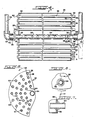
- Solar still system 10 comprises a salt gradient solar pond 12, having a plurality of evaporator modules 14 submerged therein.
- the solar pond is preferably of a long and narrow configuration to reduce the unsupported span and the construction cost of the bridge structure which supports the evaporator modules.
- the pond is preferably formed on the bottom by soil and on its sides by earthen dikes 16 and is overlayed with a suitable factory fabricated impermeable pond liner 18.
- Solar pond 12 is preferably dimensioned as follows: 8 feet to 20 feet in width; 4 feet to 12 feet in depth and may be of unlimited length.
- the evaporator modules 14 are supported from support bridges 20, of suitable construction, which span the width of the solar pond 12, such that the evaporator modules are submerged in the heat storage section 22 of the solar pond 12 and oriented parallel to the length thereof.
- evaporator modules may be positioned along the full length of solar pond 12.
- two or more transversely spaced modules may be supported from each bridge structure 20.
- the evaporator modules may be oriented perpendicular to the length of solar pond 12.
- an evaporator module 14 constructed in accordance with the present invention, is depicted comprising an elongated cylindrical housing 24, sealed off by an influent end plate 26 and an effluent end plate 28.
- End plates 26 and 28 have a plurality of aligned openings 30 formed therein for receipt of open ended heat transfer tubes 32 therethrough.
- the respective end portions of heat transfer tubes 32 are suitably sealed to the end plates 26 and 28.
- a horizontally disposed hollow support shaft 34 extends through horizontally aligned openings 36 in plates 26 and 28 along the horizontal axis of housing 24. Shaft 34 is rigidly secured and sealed to plates 26 and 28 such that rotation thereof effects rotation of the evaporator module 14.
- shaft 34 The respective ends of shaft 34 are supported for rotation in a suitable manner as by a Teflon bearing and lip seal arrangement 38.
- the influent end 40 of shaft 34 is connected to a raw feedwater conduit 42 through a suitable fitting 44.
- Conduit 42 is in communication with a reservoir or source of raw feedwater indicated by the reference numeral 46 in Figure 1.
- a control valve 48 is provided to control the flow of raw feedwater through conduit 42.
- the entire evaporator module 14 rotates about its horizontal axis and is suitably driven in a conventional manner.
- a chain and sprocket arrangement 50 secured to shaft 34 may be utilized in cooperation with a motor 52 supported on bridge 20.
- a hydraulic turbine (not shown) may be utilized to rotate shaft 34 and thereby rotate module 14.
- shaft 34 is provided with a plurality of openings 54 spaced along substantially the entire length within housing 24.
- the effluent end portion 56 of shaft 34 is closed off by a wall 58, positioned a short distance inward of end plate 28. Accordingly, all of the raw feedwater directed into shaft 34 through conduit 42 falls through openings 54 into the housing 24.
- the openings 54 are preferably sized and located in such a manner as to cause the raw feedwater to be distributed along the full length of shaft 34 in approximately uniform flow as the evaporator module 14 rotates about its horizontal axis.
- heat transfer tubes 32 have influent end sections 60 and effluent end sections 62, which respectively extend outwardly of plates 26 and 28.
- the effluent end portions of tubes 32 are provided with cavitation fins 64.
- Cavitation fins 64 are preferably formed by excising a partial section from the effluent end sections 62, as shown in Figures 6 and 7, or, alternatively, by securing a flexible tube sleeve of the same shape.
- Each cavitation fin 64 is preferably oriented such that an imaginary radial line passing through the apex thereof is always tangent to an imaginary circle that defines the direction of rotation of the corresponding heat transfer tube 32.
- the evaporator module 14 is rotated at a rate slow enough so as not to disturb the salt gradient but rapidly enough to ensure contact of the falling droplets passing through openings 54 with many of the tubes 32 within the evaporator module.
- the rotation also serves the purpose of agitating the increasingly concentrated liquid at the bottom of the evaporator housing 24 and forming thin films of this liquid as the tubes emerge in their rotation. This periodic submergence of some of the tubes also has the effect of reducing fouling and scaling.
- the optimum level of liquid in housing 24 is suitably controlled to maximize the evaporation process.
- the vapor generated during the evporation process exits the evaporator module 14 through openings 66 in the effluent end porton 56 of shaft 34 downstream from wall 58.
- the vapor rises up a vertical effluent conduit 68, secured to shaft 34 by a bearing and lip seal arrangement 38 and a fitting 44, and is directed to a heat exchanger/condenser 70, which condenses the vapor into pure product water in a conventional manner.
- This heat exchanger/condenser 70 may be either air cooled or water cooled.
- the condensed product water is then directed to its intended use or into a storage tank.
- the overall efficiency of the process may be improved by using the vapor to heat the incoming raw feedwater.
- the evaporator module 14 is preferably constructed of corrosion resistant materials.
- the module is preferably assembled with gaskets, grommets and fasteners in such a way that it can be disassembled in the field by unskilled labor for the repair and replacement of components and for the removal of scale and foulants.
- Periodic flushing of the evaporator module 14 to remove concentrate and to minimize scaling may be accomplished by allowing a large flow of feedwater to enter the evaporator module either from a higher elevation raw water storage impoundment or by pumping.
- the resultant mixture of raw water and concentrate exits through the openings 66 and is directed up the vertical exit effluent conduit 68, or alternately down a drain conduit 72, as shown in phantom lines in Figure 4.
- the flushing operation is controlled by valve 48 and an effluent valve 74 to direct the concentrate to a disposal conduit 76, to prevent the flooding of the heat exchanger/condenser 70 and to prevent untimely drainage.
- the flushing function may also be accomplished by using the evaporator module in the manner of a compressed air ejector in order to reduce the quantity of wastewater.
- the evaporator module 14 and interconnected piping may be raised to the surface of the solar pond 12 for inspection and subsequent removal if necessary.
- the submerged module 14 and conduits 42 and 68 are allowed to rise, guided by pipe sleeves 78 secured to the bridge 20.
- water is inserted through the open feedwater piping to fill the evaporator body to the extent that it will sink in manner similar to adding ballast to a ship or submarine.
- a drain 72 When a drain 72 is provided, disconnection is achieved with a quick disconnect coupling 80 and an extended operator rod 82.
- the small amount of heating medium filling the open drain pipe can be drained into a container and returned to the pond.
- the bridge may be raised by virtue of a pin and hinge arrangement (not shown) on one side of the bridge 20.
- a waste heat evaporator system is indicated generally by reference numeral 90.
- the waste heat evaporator system 90 comprises an enclosure or tank 91 having one or more evaporator modules 14 submerged therein.
- the tank 91 contains a heating liquid or medium 92, for example an available hot industrial effluent, that enters through conduit 93 and exits through conduit 94 at a rate such that a suitable depth is maintained in the tank 91.
- the evaporator module is supported by a bridge 95 similar to the previously described solar still embodiment 10.
- the tank may support a removable cover 96 to prevent the escape of vapor from the heating medium into a working area.
- the cover may be equiped with a duct 97 to recover vapor that flashes from the heating medium.
- the operation of the waste heat evaporator system 90 is identical to the previously described solar still embodiment 10 where raw feedwater enters through conduit 42 and vapor exits through conduit 68 except that it is no longer necessary to limit the speed of rotation to avoid excessive turbulence in the tank 91, and the module may be more conveniently serviced in place.
- Concentrate may be flushed from the module 14 in the same manner as previously described for the solar still embodiment 10 with the concentrate exiting the system through conduits 68 and 99 or concentrate drain 102.
- the evaporator module 14 may be submerged within a conventional channel (not shown) containing flowing heating medium wherein a downstream flow control device such as a flume or weir, maintains a suitable operating depth.
- the high rate solar still depicted in Figures 1, 2 and 3 or the waste heat evaporator depicted in Figure 9, low boiling point heat transfer fluids may be substituted for the raw feedwater to the effect that the resulting vapor may be used to generate electrical power in combination with a Rankine cycle turbine generator system.
- the evaporator module 14 as described herein may be modified by removing a portion of the hollow support shaft 34, so that the module may be utilized as a biological/chemical reactor submerged within a temperature controlled liquid body.
- a preferred embodiment of a biological/chemical reactor in accordance with the present invention is indicated by reference numeral 110.
- the reactor 110 is submerged within a containment vessel or enclosure (not shown) with connections and supports similar to the waste heat evaporator embodiment 90 and to the solar still embodiment 10.
- Chemical reactants or nutrient laden substrates enter the reactor through conduit 42 and through the truncated influent end of the hollow support shaft 111.
- the desired reaction takes place within a liquor filled reservoir 112 within the reactor 110 while said reactor rotates as described in the previous embodiments.
- the maximum liquid level 113 may be automatically maintained.
- the rotation of the reactor 110 causes each heat transfer tube 32 to periodically enter and exit the liquid reservoir 112 within the reactor 110.
- the interaction of the tubes 32 and reservoir 112 results in a beneficial agitation and mixing of liquor within the reservoir.
- the reactor 110 is preferrably submerged within an uncontaminated, carefully controlled heating or cooling medium or within the effluent of the reaction process itself which may be recirculated, with makeup heat, through the contaiment vessel for the purpose of heat recovery. Heat transfer takes place continuously through the reactor shell 24 and the heat transfer tubes 32.
- the reactor 110 may be operated in batch or continuous mode. Solids and residues are removed as described in the previous embodiments. As described the reactor module and connecting piping may be strengthened in such a way as to allow its use as a compressed air ejector during the flushing cycle to avoid dilution of the solid residues and to ensure their removal.
- reactor 110 is in the scale up of laboratory fermenters constructed of glass.
- Glass fermenters have well known advantages including inertness to reactants and observability, but usually give way to polished stainless steel contruction in pilot and commercial scale applications. Large glass fermenters would have to be excessively heavy or else be subject to breakage from internal pressure buildup or from external blows, thus allowing escape of possible dangerous reactants.
- the reactor embodiment of the present invention constructed of borosilicate glass, with the possible exception of stainless steel tube sheets, would overcome these limitations to scale-up. Its submergence in a water heating or cooling medium filled tank would obviate the problem of excess weight due to its bouyancy, protect the reactor wall from external blows, and counteract somewhat internal pressure buildup. In-situ sterilization of the contents of the reactor can be easily and quickly achieved by elevating the temperature of the heat medium in which the reactor is submerged.
- the reactor 110 is in connection with the anaerobic treatment of wastewater.
- the principal gaseous products of this biological reaction are carbon dioxide and methane.
- Typical operating problems of conventional technology are difficulty in maintaining temperatures optimal for both the acid and methane forming bacteria, excessive turbulence from high energy mixers that cause foaming and shearing of biological floc, entrapment of gas bubbles in the solids, and the buildup of acids and dissolved carbon dioxide that lowers the PH and inhibits the methane forming bacteria.
- the reactor 110 with its internal tube array, would ensure the rapid transfer of heat to the reactor center while at the same time imparting a gentle non-foaming mixing action and promote the formation of thin films of liquid that facilitate the separation and release of both the methane and carbon dioxide.
- the reactor affords the ability, within a single tank system, to rapidly raise and lower the temperature to favor either the acid forming or methane forming bacteria within, for example to limit the buildup of acids that are inhibiting the methane formers.
Landscapes
- Engineering & Computer Science (AREA)
- Chemical & Material Sciences (AREA)
- Life Sciences & Earth Sciences (AREA)
- Organic Chemistry (AREA)
- Hydrology & Water Resources (AREA)
- Environmental & Geological Engineering (AREA)
- Water Supply & Treatment (AREA)
- Sustainable Energy (AREA)
- Sustainable Development (AREA)
- Chemical Kinetics & Catalysis (AREA)
- Physics & Mathematics (AREA)
- Thermal Sciences (AREA)
- Combustion & Propulsion (AREA)
- Mechanical Engineering (AREA)
- General Engineering & Computer Science (AREA)
- Heat Treatment Of Water, Waste Water Or Sewage (AREA)
- Physical Or Chemical Processes And Apparatus (AREA)
Applications Claiming Priority (4)
| Application Number | Priority Date | Filing Date | Title |
|---|---|---|---|
| US06/766,648 US4613409A (en) | 1985-08-19 | 1985-08-19 | High rate solar still and process |
| US06/866,876 US4693304A (en) | 1985-08-19 | 1986-05-23 | Submerged rotating heat exchanger-reactor |
| US766648 | 1991-09-26 | ||
| US866876 | 1997-05-30 |
Publications (2)
| Publication Number | Publication Date |
|---|---|
| EP0212291A2 true EP0212291A2 (de) | 1987-03-04 |
| EP0212291A3 EP0212291A3 (de) | 1988-06-08 |
Family
ID=27117780
Family Applications (1)
| Application Number | Title | Priority Date | Filing Date |
|---|---|---|---|
| EP19860110021 Withdrawn EP0212291A3 (de) | 1985-08-19 | 1986-07-21 | Unter Wasser rotierender Wärmetauscherreaktor |
Country Status (2)
| Country | Link |
|---|---|
| US (1) | US4693304A (de) |
| EP (1) | EP0212291A3 (de) |
Families Citing this family (37)
| Publication number | Priority date | Publication date | Assignee | Title |
|---|---|---|---|---|
| US5575889A (en) * | 1993-02-04 | 1996-11-19 | Rosenblad; Axel E. | Rotating falling film evaporator |
| US6494995B1 (en) * | 1997-12-12 | 2002-12-17 | Hammam Jamil Girgiess Battah | Solar distillation system |
| ES2331512T3 (es) * | 2002-02-27 | 2010-01-07 | Excelerate Energy Limited Partnership | Metodo y aparato para la regasificacion de lng a bordo de un buque transportador. |
| WO2003085316A1 (en) * | 2002-03-29 | 2003-10-16 | Excelerate Energy Limited Partnership | Improved ling carrier |
| EP1667898A4 (de) | 2003-08-12 | 2010-01-20 | Excelerate Energy Ltd Partners | Wiederverdampfung an bord für flüssigerdgasträger mit alternativen antriebsanlagen |
| US8371251B2 (en) * | 2006-04-24 | 2013-02-12 | Phoenix Caliente Llc | Methods and apparatuses for heating, concentrating and evaporating fluid |
| US20130075245A1 (en) | 2009-12-16 | 2013-03-28 | F. Alan Frick | Methods and systems for heating and manipulating fluids |
| US10039996B2 (en) | 2006-04-24 | 2018-08-07 | Phoenix Callente LLC | Methods and systems for heating and manipulating fluids |
| US8801897B2 (en) | 2007-03-13 | 2014-08-12 | Heartland Technology Partners Llc | Compact wastewater concentrator and contaminant scrubber |
| US8790496B2 (en) | 2007-03-13 | 2014-07-29 | Heartland Technology Partners Llc | Compact wastewater concentrator and pollutant scrubber |
| US8741100B2 (en) | 2007-03-13 | 2014-06-03 | Heartland Technology Partners Llc | Liquid concentrator |
| US10005678B2 (en) | 2007-03-13 | 2018-06-26 | Heartland Technology Partners Llc | Method of cleaning a compact wastewater concentrator |
| US8679291B2 (en) | 2007-03-13 | 2014-03-25 | Heartland Technology Partners Llc | Compact wastewater concentrator using waste heat |
| US8540012B2 (en) * | 2008-06-13 | 2013-09-24 | Lockheed Martin Corporation | Heat exchanger |
| CN102356046A (zh) | 2009-02-12 | 2012-02-15 | 中心地带科技股份有限公司 | 利用废热的紧凑型废水浓缩器 |
| EP2454546B1 (de) | 2009-07-16 | 2015-09-02 | Lockheed Martin Corporation | Schraubenförmiges rohrbündel für wärmetauscher |
| KR20120051685A (ko) | 2009-07-17 | 2012-05-22 | 록히드 마틴 코포레이션 | 열 교환기 및 제작 방법 |
| WO2011035232A2 (en) * | 2009-09-18 | 2011-03-24 | Massachusetts Institute Of Technology | Concentrated solar power system |
| US9777971B2 (en) * | 2009-10-06 | 2017-10-03 | Lockheed Martin Corporation | Modular heat exchanger |
| US20110127022A1 (en) * | 2009-12-01 | 2011-06-02 | Lockheed Martin Corporation | Heat Exchanger Comprising Wave-shaped Fins |
| WO2012003525A1 (en) * | 2010-07-09 | 2012-01-12 | The University Of Western Australia | A desalination plant |
| US9670911B2 (en) | 2010-10-01 | 2017-06-06 | Lockheed Martin Corporation | Manifolding arrangement for a modular heat-exchange apparatus |
| US9388798B2 (en) | 2010-10-01 | 2016-07-12 | Lockheed Martin Corporation | Modular heat-exchange apparatus |
| US9429317B2 (en) * | 2010-10-05 | 2016-08-30 | Edward Stock | Wastewater evaporation apparatus and method |
| US8721771B2 (en) | 2011-01-21 | 2014-05-13 | Heartland Technology Partners Llc | Condensation plume mitigation system for exhaust stacks |
| US9296624B2 (en) | 2011-10-11 | 2016-03-29 | Heartland Technology Partners Llc | Portable compact wastewater concentrator |
| US8808497B2 (en) | 2012-03-23 | 2014-08-19 | Heartland Technology Partners Llc | Fluid evaporator for an open fluid reservoir |
| US8741101B2 (en) | 2012-07-13 | 2014-06-03 | Heartland Technology Partners Llc | Liquid concentrator |
| US8623174B1 (en) * | 2012-12-14 | 2014-01-07 | Heartland Technology Partners Llc | Liquid evaporation system with heated liquid |
| US8585869B1 (en) * | 2013-02-07 | 2013-11-19 | Heartland Technology Partners Llc | Multi-stage wastewater treatment system |
| US9199861B2 (en) | 2013-02-07 | 2015-12-01 | Heartland Technology Partners Llc | Wastewater processing systems for power plants and other industrial sources |
| US20150258464A1 (en) * | 2014-03-14 | 2015-09-17 | Donald Ramer | Method and Apparatus for Molecular Targeting and Separation of Feedstock Fluids |
| CN104464480B (zh) * | 2014-11-17 | 2016-09-07 | 河南理工大学 | 一种模拟太阳能加热盐梯度太阳池的实验方法 |
| AU2017294797A1 (en) * | 2016-07-15 | 2019-02-28 | Vapteq IP Pty Ltd | Enhanced evaporation system |
| KR101969581B1 (ko) * | 2016-11-17 | 2019-08-13 | 주식회사 엘지화학 | 올레핀계 단량체의 회수 장치 |
| WO2020243510A1 (en) | 2019-05-31 | 2020-12-03 | Heartland Technology Partners Llc | Harmful substance removal system and method |
| US20220118491A1 (en) * | 2020-10-15 | 2022-04-21 | Custom Environmental Consulting LLC | Apparatus And Method For Ballast Leachate Evaporation For Exposed Landfill Covers |
Family Cites Families (9)
| Publication number | Priority date | Publication date | Assignee | Title |
|---|---|---|---|---|
| US2735807A (en) * | 1956-02-21 | Self-cleaning apparatus for purifying | ||
| BE352290A (de) * | ||||
| US3291204A (en) * | 1961-03-16 | 1966-12-13 | Thermel Inc | Heat transfer roll |
| US3563710A (en) * | 1968-02-16 | 1971-02-16 | Monsanto Co | Polymerization apparatus |
| US3477499A (en) * | 1968-06-13 | 1969-11-11 | Edward E Goetz | Rotatable thermal transfer units |
| DE2153539A1 (de) * | 1971-10-27 | 1973-05-17 | Adolf Dipl Chem Opfermann | Verfahren und vorrichtung zur energiegewinnung |
| US4267022A (en) * | 1977-04-27 | 1981-05-12 | Pitcher Frederick L | Energy efficient process and apparatus for desalinizing water |
| AT364579B (de) * | 1977-06-24 | 1981-10-27 | Hubert Schrammel | Waermepumpenanlage |
| US4613409A (en) * | 1985-08-19 | 1986-09-23 | Volland Craig S | High rate solar still and process |
-
1986
- 1986-05-23 US US06/866,876 patent/US4693304A/en not_active Expired - Fee Related
- 1986-07-21 EP EP19860110021 patent/EP0212291A3/de not_active Withdrawn
Also Published As
| Publication number | Publication date |
|---|---|
| US4693304A (en) | 1987-09-15 |
| EP0212291A3 (de) | 1988-06-08 |
Similar Documents
| Publication | Publication Date | Title |
|---|---|---|
| US4693304A (en) | Submerged rotating heat exchanger-reactor | |
| US5132090A (en) | Submerged rotating heat exchanger-reactor | |
| US4613409A (en) | High rate solar still and process | |
| US20120292176A1 (en) | Water treatment process | |
| US10315163B2 (en) | Osmotic separation systems and methods | |
| US7491298B2 (en) | Plant for producing low deuterium water from sea water | |
| CN103608522B (zh) | 用于工业过程的可持续冷却的方法和系统 | |
| US9260689B2 (en) | Device for a photochemical process | |
| Sansaniwal | Advances and challenges in solar-powered wastewater treatment technologies for sustainable development: a comprehensive review | |
| CN101767841A (zh) | 一种利用太阳能的真空膜蒸馏水处理装置 | |
| IL206869A (en) | Method and device for a photochemical process | |
| US20140124356A1 (en) | Process for solar thermal energy production | |
| US9382132B1 (en) | Solar distillation apparatus | |
| CN107473481A (zh) | 超声吹脱‑膜蒸馏技术组合的垃圾渗滤液处理系统及方法 | |
| CN1743283B (zh) | 一种过滤吸附潜浮湿地污水处理系统及装置 | |
| CN2844113Y (zh) | 一种过滤吸附潜浮湿地污水处理装置 | |
| US3475280A (en) | Sea water desalination apparatus | |
| CN111285549B (zh) | 一种浸没式膜蒸馏组件及其污水生物处理系统 | |
| RU231154U1 (ru) | Устройство для обработки жидкостей | |
| CN105000613A (zh) | 一种应用于高含盐高结垢率废水的翻腾蒸发系统及工艺 | |
| CN216273189U (zh) | 一种抗cod污染耐结垢的高效传热蒸发结晶器 | |
| Szendrey et al. | Pollution and EnergyW7 Management Through the Anaerobic Approach | |
| CN209193729U (zh) | 一种零排放废水处理装置 | |
| CN215627446U (zh) | 餐厨沼液净化装置 | |
| SY | O LIQ |
Legal Events
| Date | Code | Title | Description |
|---|---|---|---|
| PUAI | Public reference made under article 153(3) epc to a published international application that has entered the european phase |
Free format text: ORIGINAL CODE: 0009012 |
|
| AK | Designated contracting states |
Kind code of ref document: A2 Designated state(s): DE FR GB NL SE |
|
| PUAL | Search report despatched |
Free format text: ORIGINAL CODE: 0009013 |
|
| AK | Designated contracting states |
Kind code of ref document: A3 Designated state(s): DE FR GB NL SE |
|
| 17P | Request for examination filed |
Effective date: 19881111 |
|
| 17Q | First examination report despatched |
Effective date: 19900122 |
|
| STAA | Information on the status of an ep patent application or granted ep patent |
Free format text: STATUS: THE APPLICATION IS DEEMED TO BE WITHDRAWN |
|
| 18D | Application deemed to be withdrawn |
Effective date: 19900503 |