EP0212258A2 - Circuit breaker with force generating shunt - Google Patents
Circuit breaker with force generating shunt Download PDFInfo
- Publication number
- EP0212258A2 EP0212258A2 EP86109768A EP86109768A EP0212258A2 EP 0212258 A2 EP0212258 A2 EP 0212258A2 EP 86109768 A EP86109768 A EP 86109768A EP 86109768 A EP86109768 A EP 86109768A EP 0212258 A2 EP0212258 A2 EP 0212258A2
- Authority
- EP
- European Patent Office
- Prior art keywords
- contact
- circuit breaker
- shunt
- contacts
- pivot
- Prior art date
- Legal status (The legal status is an assumption and is not a legal conclusion. Google has not performed a legal analysis and makes no representation as to the accuracy of the status listed.)
- Withdrawn
Links
Images


Classifications
-
- H—ELECTRICITY
- H01—ELECTRIC ELEMENTS
- H01H—ELECTRIC SWITCHES; RELAYS; SELECTORS; EMERGENCY PROTECTIVE DEVICES
- H01H13/00—Switches having rectilinearly-movable operating part or parts adapted for pushing or pulling in one direction only, e.g. push-button switch
- H01H13/68—Switches having rectilinearly-movable operating part or parts adapted for pushing or pulling in one direction only, e.g. push-button switch having two operating members, one for opening and one for closing the same set of contacts
-
- H—ELECTRICITY
- H01—ELECTRIC ELEMENTS
- H01H—ELECTRIC SWITCHES; RELAYS; SELECTORS; EMERGENCY PROTECTIVE DEVICES
- H01H77/00—Protective overload circuit-breaking switches operated by excess current and requiring separate action for resetting
- H01H77/02—Protective overload circuit-breaking switches operated by excess current and requiring separate action for resetting in which the excess current itself provides the energy for opening the contacts, and having a separate reset mechanism
- H01H77/10—Protective overload circuit-breaking switches operated by excess current and requiring separate action for resetting in which the excess current itself provides the energy for opening the contacts, and having a separate reset mechanism with electrodynamic opening
- H01H77/101—Protective overload circuit-breaking switches operated by excess current and requiring separate action for resetting in which the excess current itself provides the energy for opening the contacts, and having a separate reset mechanism with electrodynamic opening with increasing of contact pressure by electrodynamic forces before opening
-
- H—ELECTRICITY
- H01—ELECTRIC ELEMENTS
- H01H—ELECTRIC SWITCHES; RELAYS; SELECTORS; EMERGENCY PROTECTIVE DEVICES
- H01H77/00—Protective overload circuit-breaking switches operated by excess current and requiring separate action for resetting
- H01H77/02—Protective overload circuit-breaking switches operated by excess current and requiring separate action for resetting in which the excess current itself provides the energy for opening the contacts, and having a separate reset mechanism
- H01H77/10—Protective overload circuit-breaking switches operated by excess current and requiring separate action for resetting in which the excess current itself provides the energy for opening the contacts, and having a separate reset mechanism with electrodynamic opening
- H01H77/102—Protective overload circuit-breaking switches operated by excess current and requiring separate action for resetting in which the excess current itself provides the energy for opening the contacts, and having a separate reset mechanism with electrodynamic opening characterised by special mounting of contact arm, allowing blow-off movement
- H01H77/104—Protective overload circuit-breaking switches operated by excess current and requiring separate action for resetting in which the excess current itself provides the energy for opening the contacts, and having a separate reset mechanism with electrodynamic opening characterised by special mounting of contact arm, allowing blow-off movement with a stable blow-off position
-
- H—ELECTRICITY
- H01—ELECTRIC ELEMENTS
- H01H—ELECTRIC SWITCHES; RELAYS; SELECTORS; EMERGENCY PROTECTIVE DEVICES
- H01H77/00—Protective overload circuit-breaking switches operated by excess current and requiring separate action for resetting
- H01H77/02—Protective overload circuit-breaking switches operated by excess current and requiring separate action for resetting in which the excess current itself provides the energy for opening the contacts, and having a separate reset mechanism
- H01H77/10—Protective overload circuit-breaking switches operated by excess current and requiring separate action for resetting in which the excess current itself provides the energy for opening the contacts, and having a separate reset mechanism with electrodynamic opening
- H01H77/107—Protective overload circuit-breaking switches operated by excess current and requiring separate action for resetting in which the excess current itself provides the energy for opening the contacts, and having a separate reset mechanism with electrodynamic opening characterised by the blow-off force generating means, e.g. current loops
Definitions
- This invention relates to circuit breakers and in particular to circuit breakers having a force generating shunt for facilitating opening of contacts while maintaining contact pressure in opposition to contact repulsion forces for permitting a higher withstand.
- Current limiting circuit breakers are used to limit fault currents. More particularly, they reduce to tolerable levels both the peak fault currents and thermal energy that reach downstream equipment. Mechanical and magnetic forces that can destroy equipment are proportional to the square of the peak currents (I p )2, and thermal damage is proportional to the let through energy (I2t). Moreover, current limiting circuit breakers not only perform the function of a circuit breaker and current limiting fuse, but are also resettable and reusable. These devices can also be effectively applied to motor control as well as to power distribution systems.
- a circuit breaker includes an electrically insulating housing with an arc quenching chamber supporting a line conductor and a load conductor, a circuit breaker structure within the housing and between the conductors and comprising first and second separable contacts operable between open and closed positions, a releasable mechanism movable when released to a tripped position to effect opening of the contacts and comprising a trip device for tripping the releasable mechanism when a predetermined current overload effects deflection of the device from a latched position, carrying means carrying the first contact and including a switch arm and a contact arm, the switch arm being pivotally mounted at a first pivot for movement between open and closed positions of the contacts, the contact arm mounting the first contact and being pivotally mounted at a second pivot on the switch arm, the second contact being mounted on one of the line and load conductors, a flexible shunt electrically connected between the other of the line and load conductors and the contact arm on the side of the second pivot opposite the first
- an arc quenching chamber is provided within the housing, a circuit breaker structure within the housing and between the conductors comprising first and second separable contacts operable between open and closed position within the quenching chamber, a releasable mechanism movable when released to a tripped position to effect automatic opening of the contacts and comprising a trip device for tripping the releasable mechanism when a predetermined current overload effects deflection of the device from a latch position, means carrying the first contact and including a switch arm and a contact arm, the switch arm being pivotally mounted at a first pivot for movement between open and closed positions of the contacts, the contact arm mounting the first contact and being pivotally mounted at a second pivot point on this switch arm between the first pivot and the first contact; the second contact being mounted on one of the line and load conductors, a flexible shunt electrically connected between the other of the line and load conductors and the contact arm on the side of the second pivot opposite the first contact, the flexible s
- the circuit breaker of this invention has advantages of providing a force generating shunt used with a "blow-open" contact arm which aids in maintaining contact pressure while exciting a force to assist in forcing the contact arm open.
- the shunt structure is used in a molded case circuit breaker, it exerts a force which opposes the contact repulsion forces, thereby enabling higher withstand ratings.
- a molded case circuit breaker 10 is shown in Figure 1 and comprises a housing base 12 having a cover 14.
- the casing and the cover are assembled at a parting line 16 and create an internal compartment in which circuit breaker apparatus is disposed which includes a fixed main contact 18 and a movable main contact 20.
- Fixed and movable arcing contacts 19 and 21 respectively, are also provided.
- the fixed contacts 18, 19 are mounted on a conductor 22 to which a terminal 24 is connected.
- the movable contacts 20, 21 are mounted on a contact carrying arm 26 which is pivotally mounted at pivot 27 on a switch arm 28 (Fig. 2).
- the switch arm 28 in turn is pivotally mounted at pivot 29 on a housing frame member 30.
- a flexible conductor or shunt 32 extends from the arm 26 to a connector 34 of a conductor 36 which leads to a terminal 38.
- current flows through the circuit breaker extends from terminal 38 through the several parts 36, 34, 32, 26, 20, 18, 22 to the terminal 24, the circuit breaker also operates where the current direction is reversed.
- An operating mechanism generally indicated at 40 is provided for opening and closing the contacts by means of a conventional toggle assembly which includes toggle links 44, 46 that are pivotally interconnected at a pivot 48.
- the link 46 is pivotally connected at pivot 27a to a rotatable bracket 50.
- the pivot 27a is aligned with and separate from the pivot 27 on the switch arm 26.
- the bracket 50 is pivotally mounted on the pivot 29.
- the link 46 is pivotally connected at pivot 52 to a releasable arm or cradle 54.
- the toggle mechanism also includes a coil spring 55 in a conventional manner.
- Opening of the contacts 18, 20 is accomplished either by a handle 42 of the operating mechanism 40, or automatically tripped in response to over-current conditions occurring in the circuit.
- the contact arm 26 In the tripped position, the contact arm 26 is disposed in the position shown in Fig. 2.
- the bracket 50 supports a crossbar 56 which is interconnected with contact arms in adjacent pole units of a three pole circuit breaker for opening and closing corresponding contacts similar to the contacts 18, 20, simultaneously. Accordingly, when the operating mechanism 40 actuates the contact arm 26 between either open or closed positions, the contact arms in adjacent poles of the circuit breaker are moved correspondingly by the operating mechanism.
- a latching device generally indicated at 57 which may be actuated by an overload sensing device, such as bimetal strip 58 (Fig.1).
- the shunt 32 is comprised of shunt portions 60, 62 which are bent, or turned back, or folded over at an apex 64 to form a loop, V-shaped, or U-shaped configuration.
- One end of the shunt portion 60 is mounted at 66 to the connector 34 and the other end of the shunt is mounted at 68 on the contact arm 26. Since the current flow in the shunt 32 and the conductor 34 are in opposite directions, an electromagnetic force is generated therebetween to push the shunt upwardly against the contact arm 26.
- the contact arm rotates counterclockwise about the pivot 27 and thereby maintains contact pressure by opposing the action of a contact repulsion force that normally existing between the contacts 18, 20.
- contact blow-off occurring in conventional circuit breakers, is avoided until such time as the latch device 57 is tripped to open the breaker, whereby higher withstand ratings are available.
- the current transformer. 58 actuates the latching device 57 through a solid state trip unit to release the cradle 54 (Fig. 2), whereby the toggle mechanism trips the circuit breaker by rotating the bracket 50.
- the shunt 30 withstands these lower current overloads.
- the shunt 32 responds immediately by rotating the assembly of the switch arm 28 and contact arm 26 about the pivot 29 to a "blown open" position (Fig. 3).
- the bracket 50 remains unmoved as in Fig. 3; or as in the same position as that of Fig. 1. This happens because of a rapid increase in repellant electromagnetic forces incurred between the oppositely directed shunt portions 60, 62. Since these forces exceed the forces that are normally sustained by the shunt portions, such as at normal, or low-order overcurrents, the portions 60, 62 are literally blown apart to the shape shown in Figs. 2 and 3.
- the current transformer 58 in response to the high order overcurrent, actuates the latching device 57 through a solid state trip unit (not shown). This causes the operating mechanism 40 to trip the circuit breaker and thereby rotate the bracket 50 to the position of Fig. 2.
- the shunt design of this invention generates a force which when used with a "blow-open" contact arm, aids in maintaining contact pressure while exerting a force to assist in opening the contact arm when necessary.
- the shunt design is used in a molded case circuit breaker it exerts a force which opposes the contact repulsion forces to enable higher withstand ratings.
Abstract
Description
- This invention relates to circuit breakers and in particular to circuit breakers having a force generating shunt for facilitating opening of contacts while maintaining contact pressure in opposition to contact repulsion forces for permitting a higher withstand.
- Current limiting circuit breakers are used to limit fault currents. More particularly, they reduce to tolerable levels both the peak fault currents and thermal energy that reach downstream equipment. Mechanical and magnetic forces that can destroy equipment are proportional to the square of the peak currents (Ip)², and thermal damage is proportional to the let through energy (I²t). Moreover, current limiting circuit breakers not only perform the function of a circuit breaker and current limiting fuse, but are also resettable and reusable. These devices can also be effectively applied to motor control as well as to power distribution systems.
- Two major factors control how well the current limiting phenomenon occurs; namely, how quickly the contacts separate after initiation of a fault current, and how quickly the impedance of the air arc develops, i.e., as the contacts separate an arc is drawn between them. The success of arc limiting requires a very high contact opening speed. The faster the contacts separate after initiation of the fault current, the shorter the dwell time of the arc acting on the contacts. Thus, the volume of melting and volatilization of the contact material is minimized.
- According to the present invention, a circuit breaker includes an electrically insulating housing with an arc quenching chamber supporting a line conductor and a load conductor, a circuit breaker structure within the housing and between the conductors and comprising first and second separable contacts operable between open and closed positions, a releasable mechanism movable when released to a tripped position to effect opening of the contacts and comprising a trip device for tripping the releasable mechanism when a predetermined current overload effects deflection of the device from a latched position, carrying means carrying the first contact and including a switch arm and a contact arm, the switch arm being pivotally mounted at a first pivot for movement between open and closed positions of the contacts, the contact arm mounting the first contact and being pivotally mounted at a second pivot on the switch arm, the second contact being mounted on one of the line and load conductors, a flexible shunt electrically connected between the other of the line and load conductors and the contact arm on the side of the second pivot opposite the first contact, the flexible shunt comprising turned-back shunt portions spaced to form a loop and between which portions first repulsion magnetic forces occur that exert pressure on the contact arm to hold the contacts in the closed position, and the repulsion magnetic forces of the shunt portions expediting movement of the carrying means about the first pivot to the other position when at least one of the contact arms and the trip device is deflected from a latched position.
- Conveniently, an arc quenching chamber is provided within the housing, a circuit breaker structure within the housing and between the conductors comprising first and second separable contacts operable between open and closed position within the quenching chamber, a releasable mechanism movable when released to a tripped position to effect automatic opening of the contacts and comprising a trip device for tripping the releasable mechanism when a predetermined current overload effects deflection of the device from a latch position, means carrying the first contact and including a switch arm and a contact arm, the switch arm being pivotally mounted at a first pivot for movement between open and closed positions of the contacts, the contact arm mounting the first contact and being pivotally mounted at a second pivot point on this switch arm between the first pivot and the first contact; the second contact being mounted on one of the line and load conductors, a flexible shunt electrically connected between the other of the line and load conductors and the contact arm on the side of the second pivot opposite the first contact, the flexible shunt comprising turned-back shunt portions spaced to form a loop and between which portions first repulsion magnetic forces occur that exert pressure on the contact arm to hold the contacts in the closed position; and the repulsion magnetic forces of the shunt portions expediting movement of the carrying means about the first pivot to the open position when the trip device is deflected from a latched position.
- The circuit breaker of this invention has advantages of providing a force generating shunt used with a "blow-open" contact arm which aids in maintaining contact pressure while exciting a force to assist in forcing the contact arm open. Where the shunt structure is used in a molded case circuit breaker, it exerts a force which opposes the contact repulsion forces, thereby enabling higher withstand ratings.
- The invention will now be described, by way of example, with reference to the accompanying drawings in which:
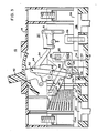
- Figure 1 is a vertical sectional view through a circuit breaker in a contact closed position and showing the shunt of this invention;
- Figure 2 is a vertical sectional view through the circuit breaker in the tripped position; and
- Figure 3 is a vertical sectional view showing the circuit breaker in a blown apart position.
- A molded
case circuit breaker 10 is shown in Figure 1 and comprises ahousing base 12 having acover 14. The casing and the cover are assembled at aparting line 16 and create an internal compartment in which circuit breaker apparatus is disposed which includes a fixedmain contact 18 and a movablemain contact 20. Fixed andmovable arcing contacts fixed contacts conductor 22 to which aterminal 24 is connected. - The
movable contacts contact carrying arm 26 which is pivotally mounted at pivot 27 on a switch arm 28 (Fig. 2). Theswitch arm 28 in turn is pivotally mounted atpivot 29 on ahousing frame member 30. A flexible conductor orshunt 32 extends from thearm 26 to aconnector 34 of aconductor 36 which leads to aterminal 38. Although current flows through the circuit breaker extends fromterminal 38 through theseveral parts terminal 24, the circuit breaker also operates where the current direction is reversed. - An operating mechanism generally indicated at 40 is provided for opening and closing the contacts by means of a conventional toggle assembly which includes
toggle links pivot 48. Thelink 46 is pivotally connected at pivot 27a to arotatable bracket 50. The pivot 27a is aligned with and separate from the pivot 27 on theswitch arm 26. Thebracket 50 is pivotally mounted on thepivot 29. Thelink 46 is pivotally connected atpivot 52 to a releasable arm orcradle 54. The toggle mechanism also includes acoil spring 55 in a conventional manner. For a more complete description of the toggle mechanism, reference is made to U.S. Patent No. 3,949,331 which is incorporated herein by reference. - Opening of the
contacts handle 42 of theoperating mechanism 40, or automatically tripped in response to over-current conditions occurring in the circuit. In the tripped position, thecontact arm 26 is disposed in the position shown in Fig. 2. Thebracket 50 supports acrossbar 56 which is interconnected with contact arms in adjacent pole units of a three pole circuit breaker for opening and closing corresponding contacts similar to thecontacts operating mechanism 40 actuates thecontact arm 26 between either open or closed positions, the contact arms in adjacent poles of the circuit breaker are moved correspondingly by the operating mechanism. - Automatic opening, or tripping, of the contacts is provided by a latching device generally indicated at 57 which may be actuated by an overload sensing device, such as bimetal strip 58 (Fig.1).
- In accordance with this invention, the
shunt 32 is comprised ofshunt portions apex 64 to form a loop, V-shaped, or U-shaped configuration. One end of theshunt portion 60 is mounted at 66 to theconnector 34 and the other end of the shunt is mounted at 68 on thecontact arm 26. Since the current flow in theshunt 32 and theconductor 34 are in opposite directions, an electromagnetic force is generated therebetween to push the shunt upwardly against thecontact arm 26. Inasmuch as the upper end of theshunt 32 is mounted at 68 on the side of the pivot 27 opposite themovable contact 26, the contact arm rotates counterclockwise about the pivot 27 and thereby maintains contact pressure by opposing the action of a contact repulsion force that normally existing between thecontacts latch device 57 is tripped to open the breaker, whereby higher withstand ratings are available. - When an overcurrent of low order occurs, the current transformer. 58 actuates the
latching device 57 through a solid state trip unit to release the cradle 54 (Fig. 2), whereby the toggle mechanism trips the circuit breaker by rotating thebracket 50. Theshunt 30 withstands these lower current overloads. - However, when an overcurrent of high order occurs, the
shunt 32 responds immediately by rotating the assembly of theswitch arm 28 and contactarm 26 about thepivot 29 to a "blown open" position (Fig. 3). Momentarily, thebracket 50 remains unmoved as in Fig. 3; or as in the same position as that of Fig. 1. This happens because of a rapid increase in repellant electromagnetic forces incurred between the oppositely directedshunt portions portions - Shortly thereafter, such as of the order of a fraction of a current cycle, the
current transformer 58 in response to the high order overcurrent, actuates thelatching device 57 through a solid state trip unit (not shown). This causes theoperating mechanism 40 to trip the circuit breaker and thereby rotate thebracket 50 to the position of Fig. 2. - By virtue of this construction lower current limiting threshold currents than are possible otherwise are provided by the
flexible shunt 32 of this invention. - Accordingly, the shunt design of this invention generates a force which when used with a "blow-open" contact arm, aids in maintaining contact pressure while exerting a force to assist in opening the contact arm when necessary. Moreover, where the shunt design is used in a molded case circuit breaker it exerts a force which opposes the contact repulsion forces to enable higher withstand ratings.
Claims (7)
Applications Claiming Priority (2)
| Application Number | Priority Date | Filing Date | Title |
|---|---|---|---|
| US06/766,303 US4656444A (en) | 1985-08-16 | 1985-08-16 | Circuit breaker with force generating shunt |
| US766303 | 1985-08-16 |
Publications (2)
| Publication Number | Publication Date |
|---|---|
| EP0212258A2 true EP0212258A2 (en) | 1987-03-04 |
| EP0212258A3 EP0212258A3 (en) | 1988-12-21 |
Family
ID=25076039
Family Applications (1)
| Application Number | Title | Priority Date | Filing Date |
|---|---|---|---|
| EP86109768A Withdrawn EP0212258A3 (en) | 1985-08-16 | 1986-07-16 | Circuit breaker with force generating shunt |
Country Status (12)
| Country | Link |
|---|---|
| US (1) | US4656444A (en) |
| EP (1) | EP0212258A3 (en) |
| JP (1) | JPS6243027A (en) |
| KR (1) | KR950003868B1 (en) |
| CN (1) | CN1014662B (en) |
| AU (1) | AU589199B2 (en) |
| BR (1) | BR8603909A (en) |
| CA (1) | CA1252814A (en) |
| ES (1) | ES2001361A6 (en) |
| IN (1) | IN164820B (en) |
| PH (1) | PH23615A (en) |
| ZA (1) | ZA865749B (en) |
Cited By (4)
| Publication number | Priority date | Publication date | Assignee | Title |
|---|---|---|---|---|
| EP0335824A1 (en) * | 1988-03-28 | 1989-10-04 | Siemens Aktiengesellschaft | Current limiting switching device with electro-dynamically openable contact pieces |
| EP0353948A2 (en) * | 1988-08-01 | 1990-02-07 | Eaton Corporation | Laminated copper assembly |
| EP0422868A2 (en) * | 1989-10-11 | 1991-04-17 | Eaton Corporation | CT quick change assembly and force transmitting spacer |
| WO1998001883A1 (en) * | 1996-07-05 | 1998-01-15 | Fki Plc | Electrical circuit breakers |
Families Citing this family (30)
| Publication number | Priority date | Publication date | Assignee | Title |
|---|---|---|---|---|
| JPH0747780Y2 (en) * | 1987-05-18 | 1995-11-01 | 三菱電機株式会社 | Circuit breaker |
| US5057806A (en) * | 1988-08-01 | 1991-10-15 | Westinghouse Electric Corp. | Crossbar assembly |
| AU621907B2 (en) * | 1988-08-01 | 1992-03-26 | Westinghouse Electric Corporation | A circuit breaker having a combination barrier and auxiliary current transformer board |
| US4939491A (en) * | 1988-08-01 | 1990-07-03 | Westinghouse Electric Corp. | Combination barrier and auxiliary CT board |
| US4890081A (en) * | 1988-08-01 | 1989-12-26 | Westinghouse Electric Corp. | CT quick change assembly |
| US4891617A (en) * | 1988-08-01 | 1990-01-02 | Westinghouse Electric Corp. | Rubber stops in outside poles |
| US4887057A (en) * | 1988-08-01 | 1989-12-12 | Westinghouse Electric Corp. | Cam roll pin assembly |
| US4887055A (en) * | 1988-08-01 | 1989-12-12 | Westinghouse Electric Corp. | Modular option deck assembly |
| US4894747A (en) * | 1988-10-12 | 1990-01-16 | Westinghouse Electric Corp. | Side plate tapered twist tab fastening device for fastening side plates to the base |
| AU628085B2 (en) * | 1988-10-12 | 1992-09-10 | Westinghouse Electric Corporation | A molded case circuit breaker having means for controlling the dynamic friction between the connection means and contact arm of the movable contact assembly |
| US4950853A (en) * | 1988-10-12 | 1990-08-21 | Westinghouse Electric Corp. | Tapered stationary contact-line copper cross reference to related applications |
| US4973927A (en) * | 1988-10-12 | 1990-11-27 | Westinghouse Electric Corp. | Two piece cradle latch, handle barrier locking insert and cover interlock for circuit breaker |
| US5027096A (en) * | 1988-10-12 | 1991-06-25 | Westinghouse Electric Corp. | Key blocks for circuit breaker |
| US4951020A (en) * | 1988-10-21 | 1990-08-21 | Westinghouse Electric Corp. | Unriveted upper link securement cross-reference to related applications |
| US5023583A (en) * | 1988-10-21 | 1991-06-11 | Westinghouse Electric Corp. | Circuit breaker contact operating structure |
| US5200724A (en) * | 1989-03-30 | 1993-04-06 | Westinghouse Electric Corp. | Electrical circuit breaker operating handle block |
| US4990873A (en) * | 1989-06-30 | 1991-02-05 | Westinghouse Electric Corp. | Reverse switching means for motor operator |
| US4982571A (en) * | 1989-08-03 | 1991-01-08 | Westinghouse Electric Corp. | Safety apparatus for superconducting magnetic energy stored system |
| US5032813A (en) * | 1990-03-09 | 1991-07-16 | Westinghouse Electric Corp. | Pinned shunt end expansion joint |
| US5142112A (en) * | 1990-04-03 | 1992-08-25 | Westinghouse Electric Corp. | Circuit breaker positive off interlock |
| US5193043A (en) * | 1990-06-26 | 1993-03-09 | Westinghouse Electric Corp. | Phase sensitivity |
| US5119054A (en) * | 1990-08-30 | 1992-06-02 | Westinghouse Electric Corp. | "E" frame pancake design |
| JP2864727B2 (en) * | 1990-11-22 | 1999-03-08 | 富士電機株式会社 | Contact device for repulsive circuit breaker |
| US5493084A (en) * | 1994-08-04 | 1996-02-20 | Eaton Corporation | Door release for circuit interrupter rotary handle mechanism |
| US5508670A (en) * | 1994-11-28 | 1996-04-16 | Eaton Corporation | Trip interlock assembly for a circuit breaker |
| US5605467A (en) * | 1995-01-19 | 1997-02-25 | Eaton Corporation | Cover for battery compartment and communications port |
| US5548261A (en) * | 1995-03-03 | 1996-08-20 | Eaton Corporation | Trip device for a circuit breaker |
| US5576677A (en) * | 1995-06-07 | 1996-11-19 | Eaton Corporation | Dual action armature |
| US5917390A (en) * | 1998-07-22 | 1999-06-29 | General Electric Company | Circuit breaker with current limiting contact structure |
| CN1253912C (en) | 2003-05-29 | 2006-04-26 | 刘平 | Electric power switch apparatus |
Citations (4)
| Publication number | Priority date | Publication date | Assignee | Title |
|---|---|---|---|---|
| US2695345A (en) * | 1950-04-19 | 1954-11-23 | Ite Circuit Breaker Ltd | Blow open, blow closed circuit breaker |
| FR1268047A (en) * | 1960-08-12 | 1961-07-28 | Elektro App Werke Veb | Electro-dynamic device used to actuate the switching elements of an electrical switch, in particular a circuit breaker |
| DE1933576A1 (en) * | 1968-07-05 | 1970-03-05 | Merlin Gerin | Current limit switch with electrodynamic compensation |
| WO1984002802A1 (en) * | 1983-01-05 | 1984-07-19 | Telemecanique Electrique | Switch with controlled closing and opening and automatic opening in case of current overloads |
Family Cites Families (3)
| Publication number | Priority date | Publication date | Assignee | Title |
|---|---|---|---|---|
| JPS6051222B2 (en) * | 1978-08-28 | 1985-11-13 | 株式会社東芝 | circuit break |
| US4281303A (en) * | 1980-03-10 | 1981-07-28 | General Electric Company | Individual circuit breaker pole trip mechanism |
| US4567455A (en) * | 1983-04-28 | 1986-01-28 | Mitsubishi Denki K.K. | Circuit interrupter |
-
1985
- 1985-08-16 US US06/766,303 patent/US4656444A/en not_active Expired - Lifetime
-
1986
- 1986-07-16 EP EP86109768A patent/EP0212258A3/en not_active Withdrawn
- 1986-07-18 IN IN542/CAL/86A patent/IN164820B/en unknown
- 1986-07-18 PH PH34035A patent/PH23615A/en unknown
- 1986-07-18 AU AU60318/86A patent/AU589199B2/en not_active Ceased
- 1986-07-30 CA CA000515016A patent/CA1252814A/en not_active Expired
- 1986-07-31 ZA ZA865749A patent/ZA865749B/en unknown
- 1986-08-08 JP JP61187656A patent/JPS6243027A/en active Pending
- 1986-08-08 KR KR1019860006552A patent/KR950003868B1/en not_active IP Right Cessation
- 1986-08-11 ES ES8600998A patent/ES2001361A6/en not_active Expired
- 1986-08-15 BR BR8603909A patent/BR8603909A/en not_active IP Right Cessation
- 1986-08-15 CN CN86105019A patent/CN1014662B/en not_active Expired
Patent Citations (4)
| Publication number | Priority date | Publication date | Assignee | Title |
|---|---|---|---|---|
| US2695345A (en) * | 1950-04-19 | 1954-11-23 | Ite Circuit Breaker Ltd | Blow open, blow closed circuit breaker |
| FR1268047A (en) * | 1960-08-12 | 1961-07-28 | Elektro App Werke Veb | Electro-dynamic device used to actuate the switching elements of an electrical switch, in particular a circuit breaker |
| DE1933576A1 (en) * | 1968-07-05 | 1970-03-05 | Merlin Gerin | Current limit switch with electrodynamic compensation |
| WO1984002802A1 (en) * | 1983-01-05 | 1984-07-19 | Telemecanique Electrique | Switch with controlled closing and opening and automatic opening in case of current overloads |
Cited By (8)
| Publication number | Priority date | Publication date | Assignee | Title |
|---|---|---|---|---|
| EP0335824A1 (en) * | 1988-03-28 | 1989-10-04 | Siemens Aktiengesellschaft | Current limiting switching device with electro-dynamically openable contact pieces |
| EP0353948A2 (en) * | 1988-08-01 | 1990-02-07 | Eaton Corporation | Laminated copper assembly |
| EP0353948A3 (en) * | 1988-08-01 | 1991-07-24 | Eaton Corporation | Laminated copper assembly |
| EP0422868A2 (en) * | 1989-10-11 | 1991-04-17 | Eaton Corporation | CT quick change assembly and force transmitting spacer |
| EP0422868A3 (en) * | 1989-10-11 | 1992-03-04 | Westinghouse Electric Corporation | Ct quick change assembly and force transmitting spacer |
| WO1998001883A1 (en) * | 1996-07-05 | 1998-01-15 | Fki Plc | Electrical circuit breakers |
| AU709410B2 (en) * | 1996-07-05 | 1999-08-26 | Hawker Siddeley Switchgear Limited | Electrical circuit breakers |
| CZ298031B6 (en) * | 1996-07-05 | 2007-05-30 | Fki Plc | Electrical circuit breaker |
Also Published As
| Publication number | Publication date |
|---|---|
| EP0212258A3 (en) | 1988-12-21 |
| ZA865749B (en) | 1987-03-25 |
| CN86105019A (en) | 1987-04-08 |
| AU6031886A (en) | 1987-02-19 |
| KR950003868B1 (en) | 1995-04-20 |
| CA1252814A (en) | 1989-04-18 |
| ES2001361A6 (en) | 1988-05-16 |
| US4656444A (en) | 1987-04-07 |
| BR8603909A (en) | 1987-03-24 |
| CN1014662B (en) | 1991-11-06 |
| JPS6243027A (en) | 1987-02-25 |
| IN164820B (en) | 1989-06-10 |
| AU589199B2 (en) | 1989-10-05 |
| KR870002622A (en) | 1987-04-06 |
| PH23615A (en) | 1989-09-11 |
Similar Documents
| Publication | Publication Date | Title |
|---|---|---|
| US4656444A (en) | Circuit breaker with force generating shunt | |
| US4489295A (en) | Circuit interrupter with improved electro-mechanical undervoltage release mechanism | |
| US4768007A (en) | Current breaking device with solid-state switch and built-in protective circuit breaker | |
| US4220934A (en) | Current limiting circuit breaker with integral magnetic drive device housing and contact arm stop | |
| EP0201731B1 (en) | Circuit breaker with arc chamber vents | |
| EP0146033B1 (en) | Electric circuit breaker with improved operating mechanism | |
| EP1098331A2 (en) | Arc chute for a molded case circuit breaker | |
| AU598234B2 (en) | Reverse loop circuit breaker with stationary conductor | |
| JPH0338694B2 (en) | ||
| US5196815A (en) | Miniature circuit breaker | |
| JPH03134931A (en) | Circuit breaker | |
| CA2364989C (en) | Circuit breaker with bypass conductor commutating current out of the bimetal during short circuit interruption and method of commutating current out of bimetal | |
| CA2789187C (en) | Limiter including a number of gas channels and electrical switching apparatus employing the same | |
| US3440579A (en) | Electric circuit breaker with overcurrent and ground fault protection | |
| EP0237355B1 (en) | Circuit breaker with trip delay magnetic circuit | |
| US4072916A (en) | Stacked circuit breakers having high interrupting capacity | |
| US3218418A (en) | Circuit breaker with arc-extinguishing means | |
| CA2425346C (en) | Circuit breaker with bypass for redirecting high transient current and associated method | |
| US5565827A (en) | Circuit breaker with current conducting blow open latch | |
| EP0204216B1 (en) | Circuit breaker with blow-open contact arm | |
| US5886599A (en) | Molded case circuit breaker having an improved electromagnetic trip | |
| JPH0329873Y2 (en) | ||
| US3999155A (en) | Circuit interrupter including a current-limiting reactor | |
| KR100557495B1 (en) | Pressure trip device for molded case circuit breaker | |
| AU2002212566A1 (en) | Circuit breaker with bypass for redirecting high transient current and associated method |
Legal Events
| Date | Code | Title | Description |
|---|---|---|---|
| PUAI | Public reference made under article 153(3) epc to a published international application that has entered the european phase |
Free format text: ORIGINAL CODE: 0009012 |
|
| AK | Designated contracting states |
Kind code of ref document: A2 Designated state(s): DE FR GB IT |
|
| PUAL | Search report despatched |
Free format text: ORIGINAL CODE: 0009013 |
|
| AK | Designated contracting states |
Kind code of ref document: A3 Designated state(s): DE FR GB IT |
|
| 17P | Request for examination filed |
Effective date: 19890517 |
|
| 17Q | First examination report despatched |
Effective date: 19900925 |
|
| STAA | Information on the status of an ep patent application or granted ep patent |
Free format text: STATUS: THE APPLICATION HAS BEEN WITHDRAWN |
|
| 18W | Application withdrawn |
Withdrawal date: 19910314 |
|
| R18W | Application withdrawn (corrected) |
Effective date: 19910314 |
|
| RIN1 | Information on inventor provided before grant (corrected) |
Inventor name: GULA, LANCE Inventor name: MCKEE, JERE LEE Inventor name: THOMAS, GLENN ROBERT Inventor name: HAUGH, CHARLES ELLSWORTH |