EP0211982A1 - Flotationstrennungsvorrichtung mit Aufwärtsströmung, induziert durch eine Gasdüse - Google Patents
Flotationstrennungsvorrichtung mit Aufwärtsströmung, induziert durch eine Gasdüse Download PDFInfo
- Publication number
- EP0211982A1 EP0211982A1 EP85110325A EP85110325A EP0211982A1 EP 0211982 A1 EP0211982 A1 EP 0211982A1 EP 85110325 A EP85110325 A EP 85110325A EP 85110325 A EP85110325 A EP 85110325A EP 0211982 A1 EP0211982 A1 EP 0211982A1
- Authority
- EP
- European Patent Office
- Prior art keywords
- gas
- chamber
- fluid
- flow
- aeration
- Prior art date
- Legal status (The legal status is an assumption and is not a legal conclusion. Google has not performed a legal analysis and makes no representation as to the accuracy of the status listed.)
- Withdrawn
Links
- 238000005188 flotation Methods 0.000 title 1
- 239000012530 fluid Substances 0.000 claims abstract description 64
- 238000005273 aeration Methods 0.000 claims abstract description 52
- XLYOFNOQVPJJNP-UHFFFAOYSA-N water Substances O XLYOFNOQVPJJNP-UHFFFAOYSA-N 0.000 claims abstract description 30
- 238000000034 method Methods 0.000 claims abstract description 24
- 230000008569 process Effects 0.000 claims abstract description 20
- 230000003134 recirculating effect Effects 0.000 claims abstract description 8
- 239000000203 mixture Substances 0.000 claims abstract description 7
- 239000000356 contaminant Substances 0.000 claims description 34
- 239000007788 liquid Substances 0.000 claims description 24
- 238000005192 partition Methods 0.000 claims description 12
- 238000012544 monitoring process Methods 0.000 claims description 5
- 239000006185 dispersion Substances 0.000 claims 2
- 230000003213 activating effect Effects 0.000 claims 1
- 239000007787 solid Substances 0.000 abstract description 15
- 239000000126 substance Substances 0.000 abstract description 8
- 238000002347 injection Methods 0.000 abstract description 4
- 239000007924 injection Substances 0.000 abstract description 4
- 230000004913 activation Effects 0.000 abstract description 3
- 230000007246 mechanism Effects 0.000 abstract description 3
- 239000008394 flocculating agent Substances 0.000 abstract description 2
- 239000007789 gas Substances 0.000 description 51
- 241000238634 Libellulidae Species 0.000 description 7
- 230000035508 accumulation Effects 0.000 description 4
- 238000009825 accumulation Methods 0.000 description 4
- 239000000523 sample Substances 0.000 description 4
- 238000013461 design Methods 0.000 description 3
- 230000006698 induction Effects 0.000 description 3
- 230000001473 noxious effect Effects 0.000 description 3
- 238000000926 separation method Methods 0.000 description 3
- LRUUNMYPIBZBQH-UHFFFAOYSA-N Methazole Chemical compound O=C1N(C)C(=O)ON1C1=CC=C(Cl)C(Cl)=C1 LRUUNMYPIBZBQH-UHFFFAOYSA-N 0.000 description 2
- 239000000306 component Substances 0.000 description 2
- 238000010276 construction Methods 0.000 description 2
- 230000002844 continuous effect Effects 0.000 description 2
- 231100000518 lethal Toxicity 0.000 description 2
- 230000001665 lethal effect Effects 0.000 description 2
- 238000012423 maintenance Methods 0.000 description 2
- HRPVXLWXLXDGHG-UHFFFAOYSA-N Acrylamide Chemical compound NC(=O)C=C HRPVXLWXLXDGHG-UHFFFAOYSA-N 0.000 description 1
- RWSOTUBLDIXVET-UHFFFAOYSA-N Dihydrogen sulfide Chemical compound S RWSOTUBLDIXVET-UHFFFAOYSA-N 0.000 description 1
- 241000196324 Embryophyta Species 0.000 description 1
- 208000036366 Sensation of pressure Diseases 0.000 description 1
- 208000027418 Wounds and injury Diseases 0.000 description 1
- 238000005452 bending Methods 0.000 description 1
- 230000000903 blocking effect Effects 0.000 description 1
- 239000006227 byproduct Substances 0.000 description 1
- 239000007795 chemical reaction product Substances 0.000 description 1
- 238000005352 clarification Methods 0.000 description 1
- 238000004140 cleaning Methods 0.000 description 1
- 230000006378 damage Effects 0.000 description 1
- 230000001627 detrimental effect Effects 0.000 description 1
- 238000011161 development Methods 0.000 description 1
- 230000000694 effects Effects 0.000 description 1
- 238000004880 explosion Methods 0.000 description 1
- 229910000037 hydrogen sulfide Inorganic materials 0.000 description 1
- 239000012535 impurity Substances 0.000 description 1
- 238000011221 initial treatment Methods 0.000 description 1
- 208000014674 injury Diseases 0.000 description 1
- 238000004519 manufacturing process Methods 0.000 description 1
- 238000012986 modification Methods 0.000 description 1
- 230000004048 modification Effects 0.000 description 1
- 239000002245 particle Substances 0.000 description 1
- 229920000642 polymer Polymers 0.000 description 1
- 230000009467 reduction Effects 0.000 description 1
- 125000006850 spacer group Chemical group 0.000 description 1
- 239000000725 suspension Substances 0.000 description 1
- 238000011144 upstream manufacturing Methods 0.000 description 1
- 238000013022 venting Methods 0.000 description 1
- 239000011800 void material Substances 0.000 description 1
- 239000003643 water by type Substances 0.000 description 1
- 238000003466 welding Methods 0.000 description 1
Images


Classifications
-
- B—PERFORMING OPERATIONS; TRANSPORTING
- B03—SEPARATION OF SOLID MATERIALS USING LIQUIDS OR USING PNEUMATIC TABLES OR JIGS; MAGNETIC OR ELECTROSTATIC SEPARATION OF SOLID MATERIALS FROM SOLID MATERIALS OR FLUIDS; SEPARATION BY HIGH-VOLTAGE ELECTRIC FIELDS
- B03D—FLOTATION; DIFFERENTIAL SEDIMENTATION
- B03D1/00—Flotation
- B03D1/14—Flotation machines
- B03D1/24—Pneumatic
-
- B—PERFORMING OPERATIONS; TRANSPORTING
- B01—PHYSICAL OR CHEMICAL PROCESSES OR APPARATUS IN GENERAL
- B01D—SEPARATION
- B01D17/00—Separation of liquids, not provided for elsewhere, e.g. by thermal diffusion
- B01D17/02—Separation of non-miscible liquids
- B01D17/0205—Separation of non-miscible liquids by gas bubbles or moving solids
-
- B—PERFORMING OPERATIONS; TRANSPORTING
- B01—PHYSICAL OR CHEMICAL PROCESSES OR APPARATUS IN GENERAL
- B01D—SEPARATION
- B01D17/00—Separation of liquids, not provided for elsewhere, e.g. by thermal diffusion
- B01D17/02—Separation of non-miscible liquids
- B01D17/0208—Separation of non-miscible liquids by sedimentation
- B01D17/0214—Separation of non-miscible liquids by sedimentation with removal of one of the phases
-
- B—PERFORMING OPERATIONS; TRANSPORTING
- B03—SEPARATION OF SOLID MATERIALS USING LIQUIDS OR USING PNEUMATIC TABLES OR JIGS; MAGNETIC OR ELECTROSTATIC SEPARATION OF SOLID MATERIALS FROM SOLID MATERIALS OR FLUIDS; SEPARATION BY HIGH-VOLTAGE ELECTRIC FIELDS
- B03D—FLOTATION; DIFFERENTIAL SEDIMENTATION
- B03D1/00—Flotation
- B03D1/02—Froth-flotation processes
- B03D1/028—Control and monitoring of flotation processes; computer models therefor
-
- B—PERFORMING OPERATIONS; TRANSPORTING
- B03—SEPARATION OF SOLID MATERIALS USING LIQUIDS OR USING PNEUMATIC TABLES OR JIGS; MAGNETIC OR ELECTROSTATIC SEPARATION OF SOLID MATERIALS FROM SOLID MATERIALS OR FLUIDS; SEPARATION BY HIGH-VOLTAGE ELECTRIC FIELDS
- B03D—FLOTATION; DIFFERENTIAL SEDIMENTATION
- B03D1/00—Flotation
- B03D1/14—Flotation machines
- B03D1/1406—Flotation machines with special arrangement of a plurality of flotation cells, e.g. positioning a flotation cell inside another
-
- B—PERFORMING OPERATIONS; TRANSPORTING
- B03—SEPARATION OF SOLID MATERIALS USING LIQUIDS OR USING PNEUMATIC TABLES OR JIGS; MAGNETIC OR ELECTROSTATIC SEPARATION OF SOLID MATERIALS FROM SOLID MATERIALS OR FLUIDS; SEPARATION BY HIGH-VOLTAGE ELECTRIC FIELDS
- B03D—FLOTATION; DIFFERENTIAL SEDIMENTATION
- B03D1/00—Flotation
- B03D1/14—Flotation machines
- B03D1/1412—Flotation machines with baffles, e.g. at the wall for redirecting settling solids
-
- B—PERFORMING OPERATIONS; TRANSPORTING
- B03—SEPARATION OF SOLID MATERIALS USING LIQUIDS OR USING PNEUMATIC TABLES OR JIGS; MAGNETIC OR ELECTROSTATIC SEPARATION OF SOLID MATERIALS FROM SOLID MATERIALS OR FLUIDS; SEPARATION BY HIGH-VOLTAGE ELECTRIC FIELDS
- B03D—FLOTATION; DIFFERENTIAL SEDIMENTATION
- B03D1/00—Flotation
- B03D1/14—Flotation machines
- B03D1/1443—Feed or discharge mechanisms for flotation tanks
- B03D1/1456—Feed mechanisms for the slurry
-
- B—PERFORMING OPERATIONS; TRANSPORTING
- B03—SEPARATION OF SOLID MATERIALS USING LIQUIDS OR USING PNEUMATIC TABLES OR JIGS; MAGNETIC OR ELECTROSTATIC SEPARATION OF SOLID MATERIALS FROM SOLID MATERIALS OR FLUIDS; SEPARATION BY HIGH-VOLTAGE ELECTRIC FIELDS
- B03D—FLOTATION; DIFFERENTIAL SEDIMENTATION
- B03D1/00—Flotation
- B03D1/14—Flotation machines
- B03D1/1443—Feed or discharge mechanisms for flotation tanks
- B03D1/1462—Discharge mechanisms for the froth
-
- B—PERFORMING OPERATIONS; TRANSPORTING
- B03—SEPARATION OF SOLID MATERIALS USING LIQUIDS OR USING PNEUMATIC TABLES OR JIGS; MAGNETIC OR ELECTROSTATIC SEPARATION OF SOLID MATERIALS FROM SOLID MATERIALS OR FLUIDS; SEPARATION BY HIGH-VOLTAGE ELECTRIC FIELDS
- B03D—FLOTATION; DIFFERENTIAL SEDIMENTATION
- B03D1/00—Flotation
- B03D1/14—Flotation machines
- B03D1/1443—Feed or discharge mechanisms for flotation tanks
- B03D1/1475—Flotation tanks having means for discharging the pulp, e.g. as a bleed stream
-
- B—PERFORMING OPERATIONS; TRANSPORTING
- B03—SEPARATION OF SOLID MATERIALS USING LIQUIDS OR USING PNEUMATIC TABLES OR JIGS; MAGNETIC OR ELECTROSTATIC SEPARATION OF SOLID MATERIALS FROM SOLID MATERIALS OR FLUIDS; SEPARATION BY HIGH-VOLTAGE ELECTRIC FIELDS
- B03D—FLOTATION; DIFFERENTIAL SEDIMENTATION
- B03D1/00—Flotation
- B03D1/14—Flotation machines
- B03D1/24—Pneumatic
- B03D1/242—Nozzles for injecting gas into the flotation tank
-
- C—CHEMISTRY; METALLURGY
- C02—TREATMENT OF WATER, WASTE WATER, SEWAGE, OR SLUDGE
- C02F—TREATMENT OF WATER, WASTE WATER, SEWAGE, OR SLUDGE
- C02F1/00—Treatment of water, waste water, or sewage
- C02F1/24—Treatment of water, waste water, or sewage by flotation
-
- C—CHEMISTRY; METALLURGY
- C02—TREATMENT OF WATER, WASTE WATER, SEWAGE, OR SLUDGE
- C02F—TREATMENT OF WATER, WASTE WATER, SEWAGE, OR SLUDGE
- C02F1/00—Treatment of water, waste water, or sewage
- C02F1/52—Treatment of water, waste water, or sewage by flocculation or precipitation of suspended impurities
-
- C—CHEMISTRY; METALLURGY
- C02—TREATMENT OF WATER, WASTE WATER, SEWAGE, OR SLUDGE
- C02F—TREATMENT OF WATER, WASTE WATER, SEWAGE, OR SLUDGE
- C02F1/00—Treatment of water, waste water, or sewage
- C02F1/40—Devices for separating or removing fatty or oily substances or similar floating material
-
- C—CHEMISTRY; METALLURGY
- C02—TREATMENT OF WATER, WASTE WATER, SEWAGE, OR SLUDGE
- C02F—TREATMENT OF WATER, WASTE WATER, SEWAGE, OR SLUDGE
- C02F2101/00—Nature of the contaminant
- C02F2101/30—Organic compounds
- C02F2101/32—Hydrocarbons, e.g. oil
-
- C—CHEMISTRY; METALLURGY
- C02—TREATMENT OF WATER, WASTE WATER, SEWAGE, OR SLUDGE
- C02F—TREATMENT OF WATER, WASTE WATER, SEWAGE, OR SLUDGE
- C02F2301/00—General aspects of water treatment
- C02F2301/04—Flow arrangements
- C02F2301/046—Recirculation with an external loop
Definitions
- the system of the present invention relates to oil/water separators. More particularly, the apparatus of the present invention relates to an oil/water separator wherein a continuous flow of oil and/or suspended particulates ladened water is circulated through a plurality of aeration cells with clean water effluent recirculated to each aeration cell, educting gas into the suspension for floatation and collecting contaminants in a suspended oil ladened froth layer and siphoning off the contaminants during the process.
- U. S. Filter Corporation manufactures a device which mixes and disburses gas in the form of fine bubbles in the body of liquid in a tank for attempting to remove contaminants from flowing water.
- This apparatus is covered by U. S. Patent No. 4,255,262, which employs a gas induction from the upper section of the respective tanks downward via a draft tube to the liquid body contained within the tank. The gas induction occurs as a given portion of the liquid portion already contained in the vessel is recirculated back through the individual cells or compartments with a centrifugal pump.
- the apparatus also utilizes a mechanical skimmer assembly, electrically driven, which serves to remove the impurity ladened froth from above the liquid level section of the tank.
- Such skimmers are moderate to high maintenance components of a separation system particularly in such corrossive environments as the oil producing and chemical plant industry.
- an upflow eductor induced air or gas separator providing a main separator tank receiving a continuous fluid flow divided into a plurality of aeration chambers with each aeration chamber providing eductor means wherein gas is educted into an upflow water stream with contaminats of suspended oil and solids in the continuous fluid flow adhering to the gas bubbles for collection in a froth layer on the top portion of the tank.
- V-shaped collection channel extending substantially the length of the tank for removal of collected oil following the sensing activation of a valve allowing the fluid level within the tank to rise, with oil and solid ladened froth being removed through the valve.
- a recirculation pump for recirculating the effluent which exits the tank following the aeration process, and a chemical injection mechanism for injecting a mixture of chemical flocculating agent entering the main separating tank.
- a primary tank would be cylindrical in shape, void of sideboard mechanical oil froth skimmers, therefore allowing maximum volumetric utilization of the area provided for in the tank.
- Vessels of this design can be fabricated to ASME code standards, if desired, and built to withstand virtually any inlet pressure common to applications found in the water clarification field. Vessels of this design are truly gas-tight and truly gas-tight vessels minimize if not totally prevent the leakage of noxious and/or lethal gases thereby greatly minimizing the chances for personal injury which may be caused by explosion and/or asphixiation.
- inlet pressure surges within the rated design pressure are not detrimental to the performance of the system. In fact, such inlet pressure surges serve as a "Super Charger", which will actually enhance the eductor/aeration performance.
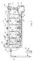
- system 10 comprises main separater tank 12 which is substantially an elongated unitary tank having a continuous side wall and rounded end portions for providing the ability to receive pressurized flow into the tank under certain circumstances.
- tank 12 which is utilized as an upflow gas eductor induced air floatation separator tank receives an inflow of oily contaminated water via flow line 14, with flow line 14 entering tank 12 at point 15 at its front end portion and projecting downward as inlet downcomer 16 for the introduction of the inlet fluid flow toward the lower portion 17 of tank 12 as indicated by arrows 18.
- the interior of tank 12 provides a plurality of downward depending bulkhead partitions 19, 21, 23, 25 and 27, substantially equally spaced apart, said downward depending bulkhead partitions defining a plurality of aeration chambers 20, 22, 24 and 26 between each successive pair of partitions.
- bulkhead partition 19 at its upper portion presents an angulated section 28, the function of which will be described further.
- each of said vertically disposed bulkhead partitions extend only partially down the interior of tank12, allowing a flow area 13 between successive aeration chambers along the lower portion of the tank between the end of each partition and the bottom wall 30 of tank 12. This would allow the continuous lateral primary flow of fluid through tank 12 following the injection of the fluid via downcomer nozzle 16 through the successive aeration chambers to the second back end portion of tank 12.
- there is vertically disposed upwardly depending baffle plate 29 which, serves to interrupt the flow out of aeration chamber 26, and enables the flow to flow in the upper region 31 of tank 12 and enter a quiescent zone or chamber 33.
- This quiescent zone 33 is necessary so that flow out of tank 12 is not ladened with air which could cause cavitation of pump 66 which will be discussed further.
- each chamber is further provided with gas eductor means 35 (See FIGURE 4), each gas eductor means 35 projecting into each aeration chamber being identical, and having identical functions.
- Each eductor means would further comprise a gas header means 37, and would also include a gas flow channel 39 projecting through the bottom wall 30 of tank 12 for allowing gas flow therethrough into each aeration chamber.
- Gas inlet 39 would further include on its uppermost portion header plate 41 which would be fixedly attached to the top shoulder portion 42 of gas injector 39 via a plurality of spacer bolts 43, providing a gas flow space 44 between injector line 39 and header plate 41 into each of said aeration chambers.
- a secondary fluid flow line 45 contained within the primary gas flow line 35, line 45 being the effluent recirculation line which recirculates fluid under pressure into header means 37 substantially adjacent header plate 41 so that the pressurized flow of fluid out of line 45 at each nozzle 52 educts gas from line 35 (arrows 47) into the fluid flow for achieving the aeration effect of gas bubbles moving upward through each of said aeration chambers during the process.
- each of gas header 35 is principally achieved from the entrained gas collected in the top portion 54 of tank 12 during the aeration process, with the flow of gas indicated by arrows 56 being educted into main gas flow line 58 for circulation into header 37 for mixture with fluid flow in fluid line 45. It should be noted that the flow of gas educted by the flow of fluid out of nozzles 52, creates a continuous effect of recirculation of the gas achieved in the aeration process.
- the apparatus would further comprise effluent exit line 59 which would receive the fluid outflow from quiescent chamber 33 during the aeration process.
- Exit line 59 would flow into valve 60 which would be a controlled valve, the function of which will be described further.
- exit line 59 would then diverge into flow line 62, which would be the principal line for removal of the clean water effluent from the system, and line 63 which would flow into second valve 64 and on into recirculation pump 66 for recirculation back through inflow line 50 for use in the eductor system. Therefore, it is seen that some of the flow which has been through the system is removed therefrom, while a portion of the flow is allowed to be recirculated back into the system.
- FIGURES 2A and 2C in combination with FIGURES 1 and 3, further illustrate in detail the means for collection of this oil ladened froth from the water in order to achieve the final clean water effluent out of the system.
- each bulkhead partition provides a means for securing a continuous channel defining a continuous oil collection trough 70, along each aeration chamber which, as seen in the FIGURES in side view, is substantially a V-shaped trough extending from its first end portion at angulated plate 28 which seals it off from the entrance chamber across each bulkhead partition, to the second end portion of the tank emptying through line 62.
- gas educted into the fluid flow within headers 37 moves upward through the fluid within each aeration chamber, with the bubbles as indicated by dots 67 within chamber 20 moving upward to the top portion 54 of tank 12.
- line 62 which is the exit line of trough 70 is provided with skim outlet valve 82 which is then opened, siphoning off all accumulation within trough 70, which is the oil and solid contaminant ladened froth contained in the trough.
- skim outlet valve 82 is closed via activation by a second density probe 75, monitoring the drop in density present.
- the contaminants are then collected in tanks downstream of tank 12 for unrelated handling.
- Valve 60 is then re-opened, and the aeration process is resumed with the water level reduced and the accumulation of froth resumes once again.
- a chemical feed unit 88 which is a standard feed unit for feeding a metered amount of a mixture of flocculant chemcial 89, usually a polymer into flow line 14 in the initial treatment of the incoming contaminated water into tank 12 for achieving optimum separation of contaminants from the water.
- monitoring gauges 90 and 92 along line 39 for monitoring the pressure within the system during the aeration process.
- gauges 95, 96, 97 and 98 each positioned on eductor inlet 39 for indicating the gas flow within inlet 39 in CFM's.
- each aeration chamber is provided with a manway 94 for access to the interior of each aeration chamber, with the manways in the normal position being in a firmly fluid/gas-tight seal during operation of the unit.
- flow line 14 introduces a flow of oil and/or solids contaminated water into the system for achieving a final clean effluent end product.
- a chemical ejection means 88 for ejecting a metered amount of chemical flocculant 89 for helping to achieve a more efficient separation.
- Flow line 14 would allow flow into tank 12 via interior inlet line downcomer 16, the flow being directed toward the lower portion 17 of tank 12 as indicated by arrows 18.
- Inlet downcomer 16 would project into a first receiving chamber 11 separated from a first aeration chamber 20 by bulkhead partition 28 which would separate the froth and gas collected to the top portion 54 of tank 12 from the incoming influent to the tank.
- the influent would then lateral flow beneath first bulkhead partition 19 into first aeration chamber 20.
- eductor means 35 located extruding into the bottom portion 13 of tank 12, would deliver a pressurized flow of fluid mixed with gas educted into the fluid flow, with the gas-entrained fluid moving upward through the primary fluid flow within first aeration cell 20 from inlet line 14.
- inlet flow would be at its most concentrated contaminant point, with the bubbles of gas moving upward through the primary fluid flow having collected a cer tain amount of the oil and solids contaminants via their adherence to the gas bubbles as they move upward in the flow.
- This main flow would then continue to move through each successive aeration chamber and receive the continuous upflow of gas educted fluid through chambers 20, 22, 24 and 26 and into the final quiescent chamber 33 for exiting through exit line 50.
- a density probe 74 would sense the level of contaminants in the system and would electrically or pneumatically partially close valve 60, thus blocking outflow from tank 12. This blockage of outflow would then create a buildup of fluid within tank 12, raising the entire fluid level as seen in FIGURES 2A and 2B, to a point where most if not all of the froth is collected within trough 70 and top portion 54 of the tank. At that point, skim outlet valve 82 would then be activated, siphoning all contents of trough 70 out of tank 12 for collection.
- a second probe 75 would then reactivate valve 60, opening it fully and allowing the flow to continue out through valve 60 into flow line 62.
- Flow line 62 would divert to a second flow line 63, the second flow line 63 allowing clean effluent to be dumped from the system into surrounding waters with safe level of contaminants in the effluent.
- Flow line 62 would recirculate some of the fluid flow under pressure back into recirculation pump 66 for injection via line 50 into header 35 in order to educt gas flow into each aeration chamber for further operation of the system.
- tank 12 is a cylindrically-shaped tank with rounded end portions for achieving a maximum ability to withstand internal pressure. This is necessary in view of the fact that often times fluid flow within line 14 may exceed certain limits, and due to the sometime noxious or harmful gases within the system, could cause a rupture in a standardly designed tank, and thus create a hazard on a rig or platform. Also, tank 12 and its related exterior piping system allows for the maximum use of space which is crucial on a rig floor, in achieving the desired result of obtaining clean effluent in the system.
- tank 12 is able to flow a quantity of fluid therethrough in a period of approximately 4 minutes, thereby achieving a great flow of fluid in the cleaning process.
- this tank requires no paddle wheel skimmers, which are mechanically operated and therefore high maintenance and expensive to run.
- the fluid contained within main tank 12 is of a greater volume, and thus can produce a greater fluid flow therethrough, with a smaller tank than the present state of the art.
- the unit is shorter in length than the present state of the art, fabrication costs are substantially less than the present state of the art, and the unit can be easily modulized resulting in multiple variations in size versus the total flow.
Landscapes
- Engineering & Computer Science (AREA)
- Life Sciences & Earth Sciences (AREA)
- Biotechnology (AREA)
- Chemical & Material Sciences (AREA)
- Chemical Kinetics & Catalysis (AREA)
- Physics & Mathematics (AREA)
- Thermal Sciences (AREA)
- Hydrology & Water Resources (AREA)
- Environmental & Geological Engineering (AREA)
- Water Supply & Treatment (AREA)
- Organic Chemistry (AREA)
- General Engineering & Computer Science (AREA)
- Physical Water Treatments (AREA)
Priority Applications (2)
| Application Number | Priority Date | Filing Date | Title |
|---|---|---|---|
| US06/548,282 US4564457A (en) | 1983-11-03 | 1983-11-03 | Upflow gas eductor induced air floatation separator |
| EP85110325A EP0211982A1 (de) | 1985-08-19 | 1985-08-19 | Flotationstrennungsvorrichtung mit Aufwärtsströmung, induziert durch eine Gasdüse |
Applications Claiming Priority (1)
| Application Number | Priority Date | Filing Date | Title |
|---|---|---|---|
| EP85110325A EP0211982A1 (de) | 1985-08-19 | 1985-08-19 | Flotationstrennungsvorrichtung mit Aufwärtsströmung, induziert durch eine Gasdüse |
Publications (1)
| Publication Number | Publication Date |
|---|---|
| EP0211982A1 true EP0211982A1 (de) | 1987-03-04 |
Family
ID=8193688
Family Applications (1)
| Application Number | Title | Priority Date | Filing Date |
|---|---|---|---|
| EP85110325A Withdrawn EP0211982A1 (de) | 1983-11-03 | 1985-08-19 | Flotationstrennungsvorrichtung mit Aufwärtsströmung, induziert durch eine Gasdüse |
Country Status (1)
| Country | Link |
|---|---|
| EP (1) | EP0211982A1 (de) |
Cited By (6)
| Publication number | Priority date | Publication date | Assignee | Title |
|---|---|---|---|---|
| FR2719507A1 (fr) * | 1994-05-04 | 1995-11-10 | Cadalpe Spa | Dispositif de clarification par flottation. |
| WO1997002080A1 (en) * | 1995-07-06 | 1997-01-23 | Zickert Products Ab | A device for the separation of oil from water |
| WO2004012867A3 (en) * | 2002-08-01 | 2004-04-08 | Axsia Serck Baker Ltd | Gas eductors and gas educators flotation separators |
| RU2232133C1 (ru) * | 2003-03-14 | 2004-07-10 | Общество с ограниченной ответственностью "Спецнефтемаштехнологии" | Установка флотационной очистки сточных вод от эмульгированной нефти и нефтепродуктов |
| RU2393119C1 (ru) * | 2008-12-01 | 2010-06-27 | Государственное образовательное учреждение высшего профессионального образования Дальневосточный государственный технический университет (ДВПИ им. В.В. Куйбышева) | Способ очистки жидкости |
| CN106890483A (zh) * | 2017-04-13 | 2017-06-27 | 江苏江涛环境工程有限公司 | 一种油水分离器及采用该油水分离器进行油水分离的方法 |
Citations (4)
| Publication number | Priority date | Publication date | Assignee | Title |
|---|---|---|---|---|
| US2730190A (en) * | 1952-02-08 | 1956-01-10 | Union Oil Co | Treatment of oil-containing water |
| US2766203A (en) * | 1953-02-09 | 1956-10-09 | Union Oil Co | Water purification process and apparatus |
| US4094783A (en) * | 1977-09-29 | 1978-06-13 | Jackson George F | Centrifugal flotation separator |
| US4255262A (en) * | 1979-03-26 | 1981-03-10 | U.S. Filter Corporation | Hydraulic powered mixing apparatus |
-
1985
- 1985-08-19 EP EP85110325A patent/EP0211982A1/de not_active Withdrawn
Patent Citations (4)
| Publication number | Priority date | Publication date | Assignee | Title |
|---|---|---|---|---|
| US2730190A (en) * | 1952-02-08 | 1956-01-10 | Union Oil Co | Treatment of oil-containing water |
| US2766203A (en) * | 1953-02-09 | 1956-10-09 | Union Oil Co | Water purification process and apparatus |
| US4094783A (en) * | 1977-09-29 | 1978-06-13 | Jackson George F | Centrifugal flotation separator |
| US4255262A (en) * | 1979-03-26 | 1981-03-10 | U.S. Filter Corporation | Hydraulic powered mixing apparatus |
Cited By (7)
| Publication number | Priority date | Publication date | Assignee | Title |
|---|---|---|---|---|
| FR2719507A1 (fr) * | 1994-05-04 | 1995-11-10 | Cadalpe Spa | Dispositif de clarification par flottation. |
| WO1997002080A1 (en) * | 1995-07-06 | 1997-01-23 | Zickert Products Ab | A device for the separation of oil from water |
| US5976368A (en) * | 1995-07-06 | 1999-11-02 | Zickert Products A.B. | Device for the separation of oil from water |
| WO2004012867A3 (en) * | 2002-08-01 | 2004-04-08 | Axsia Serck Baker Ltd | Gas eductors and gas educators flotation separators |
| RU2232133C1 (ru) * | 2003-03-14 | 2004-07-10 | Общество с ограниченной ответственностью "Спецнефтемаштехнологии" | Установка флотационной очистки сточных вод от эмульгированной нефти и нефтепродуктов |
| RU2393119C1 (ru) * | 2008-12-01 | 2010-06-27 | Государственное образовательное учреждение высшего профессионального образования Дальневосточный государственный технический университет (ДВПИ им. В.В. Куйбышева) | Способ очистки жидкости |
| CN106890483A (zh) * | 2017-04-13 | 2017-06-27 | 江苏江涛环境工程有限公司 | 一种油水分离器及采用该油水分离器进行油水分离的方法 |
Similar Documents
| Publication | Publication Date | Title |
|---|---|---|
| US4564457A (en) | Upflow gas eductor induced air floatation separator | |
| US8431009B2 (en) | Electrocoagulation reactor | |
| US4824579A (en) | Water clarification method and apparatus | |
| EP0124644B1 (de) | Verfahren und Vorrichtung zum Abtrennen von Öl aus Wasser | |
| EP0888246B1 (de) | Flotationsvorrichtung und verfahren | |
| US5603825A (en) | Multi-stage apparatus for separating immiscible fluids | |
| EP1735070B1 (de) | Trennvorrichtung | |
| US4986903A (en) | Induced static single flotation cell | |
| EP0483524A1 (de) | Verfahren und Vorrichtung für die Wasserreinigung | |
| US5011597A (en) | Single cell vertical static flow flotation unit | |
| US5080780A (en) | Single cell vertical static flow flotation unit cross-reference to related applications | |
| EP0642373B1 (de) | Verfahren und vorrichtung zum abtrennen von gasblasen und sand aus einem flüssigkeitsstrom | |
| EP0211982A1 (de) | Flotationstrennungsvorrichtung mit Aufwärtsströmung, induziert durch eine Gasdüse | |
| JP4284051B2 (ja) | 排水の生物学的浄化のための三相分離装置および設備 | |
| EP2626137B1 (de) | Mechanische Doppelzellen-Flotationsanlage mit intermittierendem Skimming | |
| EP0695719A1 (de) | Verfahren und Vorrichtung zur Flotation mit gelöster Luft und ähnliche Gas-Flüssigkeits-Kontaktverfahren | |
| EP1296771B1 (de) | Zweikammer-flotationssystem | |
| FI69407C (fi) | Anordning foer separation av tvao sinsemellan icke blandbara vaetskefaser med olika taethet | |
| KR200149548Y1 (ko) | 현탁물질 제거장치 | |
| GB2223689A (en) | Water filter | |
| JPS6283008A (ja) | ガス誘導浮遊物分離機とその分離方法 |
Legal Events
| Date | Code | Title | Description |
|---|---|---|---|
| PUAI | Public reference made under article 153(3) epc to a published international application that has entered the european phase |
Free format text: ORIGINAL CODE: 0009012 |
|
| AK | Designated contracting states |
Kind code of ref document: A1 Designated state(s): BE CH DE FR GB IT LI NL SE |
|
| STAA | Information on the status of an ep patent application or granted ep patent |
Free format text: STATUS: THE APPLICATION IS DEEMED TO BE WITHDRAWN |
|
| 18D | Application deemed to be withdrawn |
Effective date: 19870904 |
|
| RIN1 | Information on inventor provided before grant (corrected) |
Inventor name: CAIRO, JOHN A. Inventor name: JAHN, CHRISTOPHER A. |