EP0211971A2 - Mesure passive de la distance à un émetteur aéroporté à l'aide d'un simple capteur non manoeuvrant ou fixe - Google Patents
Mesure passive de la distance à un émetteur aéroporté à l'aide d'un simple capteur non manoeuvrant ou fixe Download PDFInfo
- Publication number
- EP0211971A2 EP0211971A2 EP85109912A EP85109912A EP0211971A2 EP 0211971 A2 EP0211971 A2 EP 0211971A2 EP 85109912 A EP85109912 A EP 85109912A EP 85109912 A EP85109912 A EP 85109912A EP 0211971 A2 EP0211971 A2 EP 0211971A2
- Authority
- EP
- European Patent Office
- Prior art keywords
- target
- energy signal
- range
- signal
- platform
- Prior art date
- Legal status (The legal status is an assumption and is not a legal conclusion. Google has not performed a legal analysis and makes no representation as to the accuracy of the status listed.)
- Withdrawn
Links
Images
Classifications
-
- G—PHYSICS
- G01—MEASURING; TESTING
- G01S—RADIO DIRECTION-FINDING; RADIO NAVIGATION; DETERMINING DISTANCE OR VELOCITY BY USE OF RADIO WAVES; LOCATING OR PRESENCE-DETECTING BY USE OF THE REFLECTION OR RERADIATION OF RADIO WAVES; ANALOGOUS ARRANGEMENTS USING OTHER WAVES
- G01S11/00—Systems for determining distance or velocity not using reflection or reradiation
- G01S11/02—Systems for determining distance or velocity not using reflection or reradiation using radio waves
- G01S11/04—Systems for determining distance or velocity not using reflection or reradiation using radio waves using angle measurements
Definitions
- the present invention relates to measuring the range of moving targets, and more particularly, to a method of passively measuring the range of moving targets from a single test platform which is either stationary, or moving at a constant velocity along a linear trajectory.
- a passive ranging system In a passive ranging system the position of a target, such as an aircraft or ship, is typically determined from radiant signals emanating from the target itself, rather than echo signals developed from radiant energy being transmitted towards the target, as in active ranging systems.
- the systems and methods previously developed involve the use of a variety of optical, electromagnetic and acoustic sensors, as well as the use of cooperating ground based receiving and transmitting stations. Many such systems also require a plurality of cooperating sensor units, and cross-correlation equipment.
- Such systems are generally complex, and often include operating limitations such as the ability to sense only continuously emitted signals, or the inability to be effective against targets moving at a velocity greater than the velocity of the observing vehicle itself.
- a single measuring aircraft is constrained to fly along a curved trajectory at a constant speed, while simultaneously performing a sequence of passive bearing measurements of the target aircraft relative to itself.
- Such measurements produce a geometric pattern of intersecting rays which provides the data for mathematical calculations used to determine the target's range.
- a single measuring aircraft is again used, however, it is constrained to fly along a linear trajectory at a non-constant speed (i.e., under acceleration or deceleration), while also simultaneously performing a sequence of passive bearing measurements of the target aircraft relative to itself. Again such measurements are used to produce a geometric pattern of intersecting rays which also provides the data for a mathematical solution to the target's range.
- a ranging method utilizing a succession of bearing and frequency measurements obtained at discrete periods of time from a radiant signal emitted by a target vehicle.
- the test platform carries a sensor of radiation emitted by a target vehicle.
- the emitted radiation may be pulsed or continuous.
- the sensor which may include an array antenna, beam forming circuitry provides bearing and frequency information about the source of radiation which is utilized to determine the range to the target aircraft. The velocity and direction of travel of the emitter may then also be calculated from this information.
- the method of the present invention provides for the linear movement of a radiant energy sensor at a constant velocity. At discrete times during its displacement electrical circuitry connected to the sensor provides for a sampling of the radiant energy signal transmitted by the emitter target. As a result of the combined movement of the target and sensor there is produced a geometric pattern of rays of received radiation. The bearing angles and frequencies of these rays of radiation are measured and then arithmetically combined to provide the range to the target vehicle relative to the sensor.
- the present invention is described herein with reference to the tracking of aircraft, it should be understood that the method is equally applicable to ships employing sonic sensors and to satellites employing optical sensors. It should also be noted that certain assumptions utilized in the aforementioned Golinsky patent and application are also valid here. Specifically, the target whose range is to be determined is not maneuvering, and the test aircraft is at a long range from the target so that they may be considered to be in the same horizontal plane.
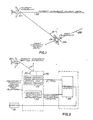
- Figure 1 illustrates a typical scenario involving the method of the present invention.
- a moving target 20, depicted as an aircraft which emits electromagnetic radiation, is shown traveling along a flight path 22.
- the path 22 is assumed to be a straight line, while the velocity of the target is assumed to be constant.
- a test platform 24, also depicted as an aircraft, carries a sensor 26 of the electromagnetic radiation emitted by target 20.
- the test platform which is also shown to be moving along a straight path 28, is constrained to operate at a constant velocity.
- Figure 2 illustrates an apparatus which could be used in implementing the present invention, and indicates how this apparatus is to be connected.
- test aircraft 24 When a target, such as aircraft 20, emits an energy signal, such as a radar pulse, the test aircraft 24 receives the signal through its antenna 30, after which it is channeled into a passive detection system 32 measuring bearing and received frequency of the emitted signal.
- a passive detection system 32 measuring bearing and received frequency of the emitted signal.
- Systems of this type are available from amnufacturers such as Litton Industries, Amecom Division. Litton Model No. ALR-73, is an example of such a passive detection system.
- the test platform 24 also includes a navigation system 34, a tracking system 36 and a display 38.
- the navigation system 34 and the tracking system 36 employ well known circuitry and are available from manufacturers such as Litton Industries. Examples of these systems include Litton's navigation system ASN-92 and Litton's tracking computer OL-77/ASQ.
- the tracking system is capable of accomplishing the steps of the mathematical calculations required to carry out the method of the present invention as hereinafter described. In the preferred embodiment of the invention this system is used, although it should be understood that a dedicated system may also be employed.
- the present invention only requires systems already aboard many test aircrafts, and therefore, it offers distinct advantages over systems which require additional bulky and expensive equipment.
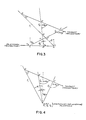
- Figure 3 illustrates the fundamental concept of the present invention.
- Vector AC shown therein represents the trajectory of test platform 24, while Vector DF represents the trajectory of target emitter 20.
- the test platform travels along vector AC at a constant velocity, V p , so as to cross points A, B and C at times T1, T2 and T3, respectively.
- target 20 is assumed to travel along Vector DF at a constant velocity, V t , so as to cross points D, E and F at times T1, T2 and T3, respectively.
- the time intervals between T1 and T2, and T2 and T3 are taken as being equal.
- the distances AB and BC traveled by the test platform during these time periods are equal, while the distances DE and EF traveled by the emitting target during these same periods, are also equal.
- the assumption of equal time intervals, and therefore, equal distances, is made only for the convenience of explaining the concept of the present invention. In actuality, however, the time between T1 and T2, and T2 and T3 need not be equal, and the distances traveled during such time periods by the platform and target also need not be equal.
- the sensor 26 of test platform 24 samples the radiant signal emitted by target 20 as the test platform crosses point A, B and C.
- the passive detection system 32 aboard the platform utilizes such samples to measure the bearing to the target aircraft 20, and the frequency of the emitter signal upon its arrival at the platform.
- tracking system 36 utilizes this data to mathematically calculate the range to target 20, as hereinafter described.
- the method of the present invention only requires three measurements to be made along the trajectory of the test platform.
- frequency measurements are required in addition to the bearing measurements utilized in the previous methods, a total of six observables are used in determining a target's range, in contrast to the four observables used in the previous methods.
- the values of the bearing and frequency measurements taken at times T1, T2 and T3 are designated as ⁇ 1, f1; ⁇ 2, f2; and ⁇ 3, f3, respectively.
- the three measured bearing angles will differ in value because of the geometry of the flight paths of the test platform and the target emitter.
- the measured frequencies will also vary, even if the frequency transmitted by the emitter is constant, because of changing doppler shifts.
- the last unknown V t is determined from the following equation: Having calculated the values of the unknowns V t and ⁇ , and knowing the time interval T between measurements (which equals the time periods between T1 and T2, and T2 and T3), it is then possible to solve for the unknown ranges from the test platform 24 to the target aircraft 20, i.e., AD, BE and CF shown in Figure 3.
- AD the time interval between measurements
- T2 and T3 the time interval
- equations 11, 12 and 13 represent the ranges at any sample points A, B and C from a test platform to a moving emitter where the test platform is traversing a linear course at a constant velocity. Once this range information has been calculated, it can be used to determine the velocity and direction of travel of the emitter target using the standard on-board systems of the test platform.
- Figure 4 illustrates the fundamental concept of the present invention where the test platform is stationary. Examples of this type of application include an air traffic control tower, a hovering helicopter, or an anchored ship.
- V p is set equal zero in equations 1, 2 and 3. Notwithstanding this, the method of determining the range to the emitter target at points D, E and F is still the same.
- AD, BE and CF then represent ranges from a common point A to the moving emitter, since points B and C are now co-located with point A.
- the measurements made at times T2 and T3 may be used with a fourth measurement to update the range calculation. This updating may be continued for as long as desired.
- the present invention can be used in a number of military applications. It should be noted, however, that in addition to such military applications, the present invention may also be used in commercial applications such as, for example, an aid to air traffic control. In such applications, the transmission frequency, f0, would be known. As such, only two sample points, e.g., A and B, rather than three would then be needed, resulting in a reduced time interval required to determine the applicable range to the target emitter.
- the calculations used to carry out the invention can be performed in essentially real time on different sets of three measurements, where each set is determined by the passive detection system to have resulted from a distinct emitter. Therefore, the number of emitters that may be positioned by the technique is limited only by the number of allocated track files in the tracking system.
Landscapes
- Physics & Mathematics (AREA)
- Engineering & Computer Science (AREA)
- General Physics & Mathematics (AREA)
- Radar, Positioning & Navigation (AREA)
- Remote Sensing (AREA)
- Radar Systems Or Details Thereof (AREA)
- Optical Radar Systems And Details Thereof (AREA)
Priority Applications (2)
| Application Number | Priority Date | Filing Date | Title |
|---|---|---|---|
| US06/681,695 US4558323A (en) | 1981-11-25 | 1984-12-14 | Passive ranging of an airborne emitter by a single sensor |
| EP85109912A EP0211971A3 (fr) | 1985-08-07 | 1985-08-07 | Mesure passive de la distance à un émetteur aéroporté à l'aide d'un simple capteur non manoeuvrant ou fixe |
Applications Claiming Priority (1)
| Application Number | Priority Date | Filing Date | Title |
|---|---|---|---|
| EP85109912A EP0211971A3 (fr) | 1985-08-07 | 1985-08-07 | Mesure passive de la distance à un émetteur aéroporté à l'aide d'un simple capteur non manoeuvrant ou fixe |
Publications (2)
| Publication Number | Publication Date |
|---|---|
| EP0211971A2 true EP0211971A2 (fr) | 1987-03-04 |
| EP0211971A3 EP0211971A3 (fr) | 1987-08-12 |
Family
ID=8193669
Family Applications (1)
| Application Number | Title | Priority Date | Filing Date |
|---|---|---|---|
| EP85109912A Withdrawn EP0211971A3 (fr) | 1981-11-25 | 1985-08-07 | Mesure passive de la distance à un émetteur aéroporté à l'aide d'un simple capteur non manoeuvrant ou fixe |
Country Status (1)
| Country | Link |
|---|---|
| EP (1) | EP0211971A3 (fr) |
Cited By (1)
| Publication number | Priority date | Publication date | Assignee | Title |
|---|---|---|---|---|
| EP1471364A3 (fr) * | 2003-04-21 | 2006-03-29 | Northrop Grumman Corporation | Procédé d'estimation passif de position et de vitesse d'un émetteur en utilisant seulement des mesures de direction sans avoir besoin d'accélérer l'observateur |
Family Cites Families (4)
| Publication number | Priority date | Publication date | Assignee | Title |
|---|---|---|---|---|
| US2968034A (en) * | 1955-08-16 | 1961-01-10 | Itt | Doppler frequency position fixing method |
| US3378842A (en) * | 1967-02-20 | 1968-04-16 | Bunker Ramo | Method and apparatus for emitter location detection |
| US4179697A (en) * | 1978-01-27 | 1979-12-18 | Grumman Aerospace Corporation | Passive ranging method |
| US4613867A (en) * | 1984-01-09 | 1986-09-23 | Grumman Aerospace Corporation | Passive ranging of an airborne emitter by a single non-maneuvering or stationary sensor |
-
1985
- 1985-08-07 EP EP85109912A patent/EP0211971A3/fr not_active Withdrawn
Cited By (1)
| Publication number | Priority date | Publication date | Assignee | Title |
|---|---|---|---|---|
| EP1471364A3 (fr) * | 2003-04-21 | 2006-03-29 | Northrop Grumman Corporation | Procédé d'estimation passif de position et de vitesse d'un émetteur en utilisant seulement des mesures de direction sans avoir besoin d'accélérer l'observateur |
Also Published As
| Publication number | Publication date |
|---|---|
| EP0211971A3 (fr) | 1987-08-12 |
Similar Documents
| Publication | Publication Date | Title |
|---|---|---|
| US4613867A (en) | Passive ranging of an airborne emitter by a single non-maneuvering or stationary sensor | |
| US5724125A (en) | Determination of wind velocity using a non-vertical LIDAR scan | |
| US4828382A (en) | Passive radio altimeter | |
| EP0237223B1 (fr) | Procédé et dispositif de détermination passive de distance | |
| US5432520A (en) | SAR/GPS inertial method of range measurement | |
| US6163297A (en) | Apparatus and method for locating an emitter using RF carrier or PRF measurement ratios | |
| US7508344B2 (en) | Systems and methods for TDOA/FDOA location | |
| US5774087A (en) | Apparatus for measuring moving emitter elevation and azimuth direction from doppler change measurements | |
| CN102004244B (zh) | 多普勒直接测距法 | |
| US5475393A (en) | Precision landing system | |
| US4179697A (en) | Passive ranging method | |
| US4558323A (en) | Passive ranging of an airborne emitter by a single sensor | |
| RU2735744C1 (ru) | Способ обзорной однопозиционной трилатерационной некогерентной радиолокации воздушных целей | |
| RU2108613C1 (ru) | Радионавигационная система для контроля полета и посадки летательных аппаратов "багис-с" | |
| US4445120A (en) | Radiosonde | |
| US3090957A (en) | Aircraft guiding system | |
| CA1254292A (fr) | Determination passive de la distance d'un emetteur aeroporte au moyen d'un capteur stationnaire unique | |
| JP3738521B2 (ja) | 飛しょう体誘導装置 | |
| JPH07117580B2 (ja) | 単一非操縦または固定センサ−による航空エミツタ−の消極測距方法 | |
| RU2238521C1 (ru) | Способ определения векторов воздушной и земной скоростей, угла сноса летательного аппарата и комплексное лазерное устройство его реализации | |
| RU2778179C1 (ru) | Способ авиационной ближней радионавигации | |
| RU2363009C1 (ru) | Система для определения пространственного положения объекта | |
| US2859436A (en) | Self-contained radio navigation system | |
| JPS6238376A (ja) | 衛星利用の位置測定装置 | |
| Buell | Doppler Radar Systems for Helicopters |
Legal Events
| Date | Code | Title | Description |
|---|---|---|---|
| PUAI | Public reference made under article 153(3) epc to a published international application that has entered the european phase |
Free format text: ORIGINAL CODE: 0009012 |
|
| AK | Designated contracting states |
Kind code of ref document: A2 Designated state(s): DE FR GB |
|
| PUAL | Search report despatched |
Free format text: ORIGINAL CODE: 0009013 |
|
| AK | Designated contracting states |
Kind code of ref document: A3 Designated state(s): DE FR GB |
|
| 17P | Request for examination filed |
Effective date: 19871002 |
|
| 17Q | First examination report despatched |
Effective date: 19890921 |
|
| STAA | Information on the status of an ep patent application or granted ep patent |
Free format text: STATUS: THE APPLICATION IS DEEMED TO BE WITHDRAWN |
|
| 18D | Application deemed to be withdrawn |
Effective date: 19900202 |
|
| RIN1 | Information on inventor provided before grant (corrected) |
Inventor name: GOLINSKY, MARTIN |