EP0211761A1 - Portable personal collector for analysing dust - Google Patents
Portable personal collector for analysing dust Download PDFInfo
- Publication number
- EP0211761A1 EP0211761A1 EP86401715A EP86401715A EP0211761A1 EP 0211761 A1 EP0211761 A1 EP 0211761A1 EP 86401715 A EP86401715 A EP 86401715A EP 86401715 A EP86401715 A EP 86401715A EP 0211761 A1 EP0211761 A1 EP 0211761A1
- Authority
- EP
- European Patent Office
- Prior art keywords
- central
- cover
- face
- cap
- sensor according
- Prior art date
- Legal status (The legal status is an assumption and is not a legal conclusion. Google has not performed a legal analysis and makes no representation as to the accuracy of the status listed.)
- Granted
Links
- 239000000428 dust Substances 0.000 title claims abstract description 41
- 238000011045 prefiltration Methods 0.000 claims abstract description 37
- 239000006260 foam Substances 0.000 claims abstract description 25
- 230000002093 peripheral effect Effects 0.000 claims abstract description 19
- 230000000717 retained effect Effects 0.000 claims description 7
- 210000004072 lung Anatomy 0.000 claims description 4
- 238000011144 upstream manufacturing Methods 0.000 claims description 2
- 230000000694 effects Effects 0.000 description 6
- 238000001914 filtration Methods 0.000 description 6
- 230000008859 change Effects 0.000 description 4
- 230000008901 benefit Effects 0.000 description 3
- 230000006872 improvement Effects 0.000 description 3
- 239000011148 porous material Substances 0.000 description 2
- 230000009471 action Effects 0.000 description 1
- 230000006978 adaptation Effects 0.000 description 1
- 239000000853 adhesive Substances 0.000 description 1
- 230000001070 adhesive effect Effects 0.000 description 1
- 230000033228 biological regulation Effects 0.000 description 1
- 230000005484 gravity Effects 0.000 description 1
- 238000012423 maintenance Methods 0.000 description 1
- 230000014759 maintenance of location Effects 0.000 description 1
- 230000004048 modification Effects 0.000 description 1
- 238000012986 modification Methods 0.000 description 1
- 230000009466 transformation Effects 0.000 description 1
- 230000001131 transforming effect Effects 0.000 description 1
Images

Classifications
-
- G—PHYSICS
- G01—MEASURING; TESTING
- G01N—INVESTIGATING OR ANALYSING MATERIALS BY DETERMINING THEIR CHEMICAL OR PHYSICAL PROPERTIES
- G01N1/00—Sampling; Preparing specimens for investigation
- G01N1/02—Devices for withdrawing samples
- G01N1/22—Devices for withdrawing samples in the gaseous state
- G01N1/2202—Devices for withdrawing samples in the gaseous state involving separation of sample components during sampling
- G01N1/2205—Devices for withdrawing samples in the gaseous state involving separation of sample components during sampling with filters
-
- G—PHYSICS
- G01—MEASURING; TESTING
- G01N—INVESTIGATING OR ANALYSING MATERIALS BY DETERMINING THEIR CHEMICAL OR PHYSICAL PROPERTIES
- G01N1/00—Sampling; Preparing specimens for investigation
- G01N1/02—Devices for withdrawing samples
- G01N1/22—Devices for withdrawing samples in the gaseous state
- G01N1/24—Suction devices
-
- G—PHYSICS
- G01—MEASURING; TESTING
- G01N—INVESTIGATING OR ANALYSING MATERIALS BY DETERMINING THEIR CHEMICAL OR PHYSICAL PROPERTIES
- G01N1/00—Sampling; Preparing specimens for investigation
- G01N1/02—Devices for withdrawing samples
- G01N1/22—Devices for withdrawing samples in the gaseous state
- G01N1/2202—Devices for withdrawing samples in the gaseous state involving separation of sample components during sampling
- G01N2001/222—Other features
- G01N2001/2223—Other features aerosol sampling devices
Landscapes
- Health & Medical Sciences (AREA)
- Life Sciences & Earth Sciences (AREA)
- Biochemistry (AREA)
- Immunology (AREA)
- Molecular Biology (AREA)
- Physics & Mathematics (AREA)
- Chemical & Material Sciences (AREA)
- Analytical Chemistry (AREA)
- Engineering & Computer Science (AREA)
- General Health & Medical Sciences (AREA)
- General Physics & Mathematics (AREA)
- Biomedical Technology (AREA)
- Pathology (AREA)
- Sampling And Sample Adjustment (AREA)
- Filtering Of Dispersed Particles In Gases (AREA)
- Analysing Materials By The Use Of Radiation (AREA)
- Investigating Or Analysing Materials By Optical Means (AREA)
- Investigating Or Analyzing Materials By The Use Of Fluid Adsorption Or Reactions (AREA)
- Respiratory Apparatuses And Protective Means (AREA)
Abstract
Le couvercle (15) qui entoure la coupelle rotative (6) porte un chapeau (30) dans lequel un bloc de préfiltration (24) supporte une coupelle auxiliaire (28) contenant une mousse filtrante (29) et ménage avec ce chapeau (30) un espace périphérique extérieur (33) qui communique avec un volume annulaire (34) ménagé sous ce bloc de préfiltration (24) autour de l'entrée d'air centrale (21) en direction de la coupelle rotative (6) pour la retenue des poussières les plus grosses.The cover (15) which surrounds the rotary cup (6) carries a cap (30) in which a pre-filtration block (24) supports an auxiliary cup (28) containing a filter foam (29) and cleans with this cap (30) an outer peripheral space (33) which communicates with an annular volume (34) formed under this pre-filtration block (24) around the central air inlet (21) in the direction of the rotary cup (6) for retaining the coarsest dust.
Description
Capteur individuel portatif amélioré pour analyse d'empoussiérage.Improved portable individual sensor for dust analysis.
L'invention a pour objet un capteur individuel portatif, que toute personne peut porter sur elle, servant à prélever dans l'atmosphère qui entoure cette personne les poussières en suspension et à retenir ces poussières en vue d'analyse ultérieure.The subject of the invention is a portable individual sensor, which any person can carry with him, serving to take from the atmosphere which surrounds this person the suspended dust and to retain this dust for later analysis.
Ce capteur est du même genre que celui qui est décrit dans le document FR.A-2 531 534 ; il est conçu pour retenir les poussières qui ont des dimensions telles qu'elles peuvent pénétrer dans les alvéoles pulmonaires de la personne qui le porte et y être retenues. A l'aide de ce capteur on peut évaluer et même doser la quantité de poussières dites respirables qu'une personne a pu inhaler pendant une période donnée.This sensor is of the same kind as that described in document FR.A-2,531,534; it is designed to retain dust that has dimensions such that it can enter and be retained in the lungs of the person wearing it. Using this sensor you can assess and even measure the amount of so-called breathable dust that a person has been able to inhale during a given period.
Le capteur décrit dans le document cité ci-dessus donne satisfaction mais il a été constaté à l'usage qu'il supporte mal de fonctionner dans une atmosphère fortement empoussiérée ou dans une atmosphère qui contient une quantité élevée de poussières de dimensions supérieures à celles des poussières respirables.The sensor described in the document cited above is satisfactory, but it has been found in use that it cannot bear to function in a strongly dusty atmosphere or in an atmosphere which contains a high quantity of dust of dimensions greater than those of respirable dust.
En effet, ce capteur est équipé d'un bloc filtrant dans lequel sont retenues les poussières considérées comme respirables et dont la grosseur est inférieure à 5 microns, ainsi qu'on l'admet généralement. Ce bloc filtrant est précédé d'un bloc de préfiltration destiné à retenir les poussières dont la grosseur est supérieure à 5 microns ; autrement dit, le bloc de préfiltration réalise dans les poussières en suspension dans le milieu environnant, qui sont aspirées par le capteur, une coupure à la façon d'un filtre passe-bas afin de ne laisser arriver au bloc filtrant que les poussières comprises dans la gamme inférieure à 5 microns. Dans le document précité, il a été précisé que le bloc filtrant retient les poussières dont la grosseur est comprise entre 0,5 et 5 microns parce que l'on admet aussi que les poussières inférieures à 0,5 micron sont trop fines pour être retenues par le bloc filtrant et probablement aussi par les poumons. Les valeurs indiquées ont une importance relative et le capteur peut être adapte faciloment à des gammes de valeurs différentes.In fact, this sensor is equipped with a filtering block in which the dust considered to be breathable and whose size is less than 5 microns is retained, as is generally accepted. This filter block is preceded by a prefiltration block intended to retain dust whose size is greater than 5 microns; in other words, the pre-filtration unit performs a cut in the dust suspended in the surrounding environment, which are sucked in by the sensor, in the manner of a low-pass filter in order to allow the dust unit to arrive only at the dust included in the range less than 5 microns. In the aforementioned document, it was specified that the filtering block retains dust whose size is between 0.5 and 5 microns because it is also admitted that dust less than 0.5 micron is too fine to be retained by the filter block and probably also by the lungs. Values indicated are of relative importance and the sensor can be easily adapted to different ranges of values.
J est apparu à l'usage que la conception même du capteur qui est l'objet du document cité plus haut comporte un inconvénient quand on utilise le capteur dans une atmosphère chargée de nombreuses poussières dont la grosseur est supérieure à 5 microns ou à une autre valeur comparable qui serait retenue comme valeur de coupure du bloc de préfiltration. On constate en effet dans ce cas que le capteur est engorgé de manière plus ou moins rapide par les poussières les plus grosses.It has become apparent to use that the very design of the sensor which is the subject of the document cited above has a drawback when the sensor is used in an atmosphere charged with numerous dusts the size of which is greater than 5 microns or another comparable value which would be used as the cut-off value for the pre-filtration block. It can be seen in this case that the sensor is clogged more or less quickly by the coarsest dust.
Le but principal de l'invention est de remédier à cette situation et d'apporter une conception générale d'un capteur individuel de poussières du type défini ci-dessus capable de séparer et de contenir une quantité élevée de poussières de grosseur supérieure à une valeur de coupure déterminée.The main object of the invention is to remedy this situation and to provide a general design of an individual dust sensor of the type defined above capable of separating and containing a large quantity of dust of size greater than a value determined cutoff.
Un but secondaire de l'invention est de parvenir à une conception générale de ce capteur individuel de poussières ayant l'avantage expliqué ci-dessus susceptible d'être adapté facilement, du fait de sa conception même, à une quantité beaucoup plus considérable que la quantité envisagée initialement de poussières de grosseur supérieure à la valeur de coupure prévue.A secondary object of the invention is to arrive at a general design of this individual dust sensor having the advantage explained above, capable of being easily adapted, by virtue of its very design, to a much more considerable quantity than the initially envisaged quantity of dust of size greater than the planned cut-off value.
Dans un capteur portatif individuel de poussières susceptibles d'être retenues dans les poumons, ayant un couvercle à axe général longitudinal, avec une entrée d'air centrale et au moins une sortie d'air latérale, une coupelle montée rotative autour dudit axe à l'intérieur du couvercle et contenant une couronne en mousse filtrante à canal central d'arrivée d'air, un chapeau coiffant l'entrée d'air centrale du couvercle et se terminant par une paroi extrême à entrée d'air centrale, ce chapeau contenant un bloc de préfiltration disposé en amont de l'entrée d'air centrale du couvercle et terminé par une première face extrême éloignée du couvercle, selon l'invention le bloc de préfiltration a une ouverture centrale de passage raccordée à l'entrée d'air centrale du couvercle et ce bloc de préfiltration est supporté à l'intérieur du chapeau en laissant libre par rapport à ce chapeau un espace périphérique extérieur, cependant que la première face extrême de ce bloc de préfiltration est garnie d'une paroi d'impact imperméable au gaz qui obture l'entrée de l'ouverture centrale de passage.In an individual portable dust collector capable of being retained in the lungs, having a cover with a general longitudinal axis, with a central air inlet and at least one lateral air outlet, a cup mounted rotatably around said axis at l inside the cover and containing a filter foam crown with central air inlet channel, a cap covering the central air inlet of the cover and ending in an end wall with central air inlet, this cap containing a prefiltration block disposed upstream of the central air inlet of the cover and terminated by a first end face remote from the cover, according to the invention the prefiltration block has a central passage opening connected to the central air inlet of the cover and this prefiltration block is supported inside the cap leaving an external peripheral space relative to this cap , however that the first end face of this prefiltration block is provided with a gas-impermeable impact wall which closes the entrance to the central passage opening.
De préférence, le bloc de préfiltration est conformé et supporté pour limiter avec le couvercle et avec le chapeau un volume annulaire qui est en communication avec l'espace périphérique et qui entoure l'ouverture centrale de passage raccordée à l'entrée d'air centrale.Preferably, the prefiltration block is shaped and supported to limit with the cover and with the cap an annular volume which is in communication with the peripheral space and which surrounds the central passage opening connected to the central air inlet .
Selon un mode de réalisation, la face extrême extérieure du couvercle est pourvue d'un bossage central traversé par le passage central raccordé à l'ouverture centrale de passage d'air du bloc de préfiltration, ce bossage central ayant en sens transversal une grosseur inférieure à celle du chapeau. Le bloc de préfiltration est supporté par ce bossage central. Quand le volume annulaire mentionné ci-dessus existe, il est limité en sens transversal par le bossage central et par le chapeau et en sens longitudinal par le couvercle et par le bloc de préfiltration.According to one embodiment, the outer outer face of the cover is provided with a central boss crossed by the central passage connected to the central air passage opening of the prefiltration block, this central boss having in transverse direction a smaller size. to that of the hat. The prefiltration block is supported by this central boss. When the annular volume mentioned above exists, it is limited in transverse direction by the central boss and by the cap and in longitudinal direction by the cover and by the pre-filtration block.
De préférence, la paroi d'impact imperméable est une paroi munie d'un bord périphérique relevé s'étendant longitudinalement à l'opposé de la couronne en mousse filtrante.Preferably, the impermeable impact wall is a wall provided with a raised peripheral edge extending longitudinally opposite the ring of filter foam.
Selon un mode de réalisation de l'invention, ce bord périphérique est prolongé comme un cylindre creux en direction du couvercle, dans l'espace périphérique mentionné plus haut, sur une fraction substantielle de la longueur en sens axial du bloc de préfiltration, en entourant ce dernier sans contact avec lui.According to one embodiment of the invention, this peripheral edge is extended like a hollow cylinder in the direction of the cover, in the peripheral space mentioned above, over a substantial fraction of the length in axial direction of the pre-filtration block, by surrounding the latter without contact with him.
Avantageusement, l'ouverture centrale du chapeau est traversée librement par une tige qui s'étend à l'extérieur en passant par cette ouverture à partir de la paroi d'impact et cette tige porte à son extrémité libre extérieure un masque qui s'étend devant la face extrême du chapeau. La couronne en mousse filtrante est contenue dans la coupelle rotative en limitant un volume libre avec le fond de cette coupelle.Advantageously, the central opening of the cap is freely traversed by a rod which extends outside passing through this opening from the impact wall and this rod carries at its external free end a mask which extends in front of the extreme face of the hat. The filter foam crown is contained in the rotating cup by limiting a free volume with the bottom of this cup.
De préférence, la face intérieure de la paroi extrême du chapeau a un prolongement intérieur à flanc incurvé concave qui s'avance concentriquement audit passage central à l'intérieur du canal central de la couronne en mousse filtrante tandis que la face intérieure de la coupelle a aussi une protubérance à flanc incurvé concave qui s'avance à l'intérieur du canal central coaxialement à la couronne en mousse filtrante.Preferably, the inner face of the end wall of the cap has an inner extension with a concave curved flank which advances concentrically to said central passage inside the central channel of the filter foam crown while the inner face of the cup has also a protuberance with a concave curved flank which projects inside the central channel coaxially with the filter foam crown.
Pour mieux faire comprendre le perfectionnement apporté au capteur individuel portatif et pour en faire apprécier les avantages, on donnera maintenant une description d'un mode préféré de réalisation et d'une variante possible. On se reportera aux dessins annexés dans lesquels :
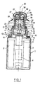
- - la figure 1 est une vue en élévation en coupe par un plan passant par l'axe général d'un capteur individuel perfectionné selon l'invention,
- - la figure 2 est une vue analogue à la fig. 1 en élévation et en coupe montrant une variante possible.
- FIG. 1 is an elevation view in section through a plane passing through the general axis of an improved individual sensor according to the invention,
- - Figure 2 is a view similar to FIG. 1 in elevation and in section showing a possible variant.
Le capteur représenté a une structure analogue à celle du capteur décrit dans le document précité qui doit être considéré comme incorporé au présent texte par la citation qui en est faite. On ne décrira donc en détail que le perfectionnement apporté par la présente invention en relation avec les pièces environnantes. Un corps creux 1 contient un moteur 2 et des sources d'énergie électrique en même temps qu'un circuit de régulation 4. L'arbre du moteur 2 sort du corps 1 à travers un palier 5 et il porte par son extrémité libre une coupelle rotative 6 ouverte en direction opposée au corps 1. La face intérieure 7 du fond de cette coupelle 6 présente une protubérance centrale 8 à flanc incurvé concave se raccordant avec cette surface intérieure 7. La face intérieure 9 de la pami latérale de cette même coupelle 6 a un épaulement circulaire 10 éloigné à la face intérieure 7 du fond. Une couronne 11 en mousse filtrante ayant un canal central 12 est contenue dans la coupelle 6; elle s'étend entre le bord libre extrême de l'épaulement 10 de sorte qu'il existe entre la face extrême 13 de la couronne 11 et la face interne 7 du fond un volume libre 14. La protubérance centrale 8 s'étend plus loin que le plan transversal qui contient l'épaulement 10 de sorte qu'elle pénètre à l'intérieur du canal central 12.The sensor shown has a structure similar to that of the sensor described in the aforementioned document which must be considered as incorporated into the present text by the citation which is made thereof. We will therefore describe in detail only the improvement provided by the present invention in relation to the surrounding parts. A
L'ensemble de la coupelle 6 avec la couronne 1 est enfermé dans un couvercle 15 qui se fixe au corps de manière démontable. Ce couvercle 15 a dans sa paroi latérale des trous 16 de sortie d'air et sa paroi extrême 17 éloignée du corps 1 comprend un bossage central extérieur 18 ; la face interne de cette paroi extrême 17 a à l'opposé du bossage 18 un prolongement intérieur 19 à flanc incurvé concave qui s'avance à l'intérieur du canal central 12 de la couronne 11 En variante le bossage central 18 pourrait être une pièce rapportée.The whole of the
Le corps 1 et le couvercle 15 ont un axe général longitudinal 20 indiqué par un trait mixte autour duquel sont disposés aussi, coaxialement, la coupelle rotative 6 avec la protubérance centrale 8, la couronne 11 et son canal central 12, le couvercle 15 avec le bossage 18 et le prolongement 19. Ces deux dernières pièces, c'est à dire le bossage 18 et le prolongement 19 sont traversés par un passage central 21 dont l'axe est confondu avec l'axe 20.The
Le bossage central 18 se termine par une face extrême plane22 et par une bordure interne saillante 23 qui entoure le passage central 21. Cette face plane 22 et cette bordure interne 23 servent à tenir en position un bloc de préfiltration 24, réalisé en mousse filtrante de préférence, qui a une ouverture centrale de passage 25 dans laquelle s'ajuste la bordure interne saillante 23. A l'opposé de sa face extrême par laquelle il est supporté par le bossage central 18, le bloc de préfiltration 24 se termine par une face extrême 26, qui est recouverte d'une paroi d'impact 27 étanche au gaz qui obture l'entrée de l'ouverture centrale de passage 25. Cette paroi d'impact pourrait être un simple disque fixé, par exemple à l'aide d'un.adhésif, à la face extrême 26. Il est préférable que la paroi d'impact 27 possède un bord extérieur étendu en sens longitudinal la transformant en une coupelle auxiliaire 28 dont le volume creux est tourné à l'opposé du bloc de préfiltration 24. Avantageusement, cette coupelle auxiliaire 28 contient aussi une mousse filtrante 29.The
L'ensemble qui vient d'être décrit et qui est supporté par le bossage central 18 est contenu dans un chapeau 30 ; ce dernier est appliqué par son bord extrême libre contre la face extérieure de la paroi extrême 17 du couvercle 15 auquel il est fixé de manière démontable. Ce chapeau 30 est coaxial à l'axe général 20 et il est terminé à l'opposé du couvercle 15 par une paroi extrême 31 dans laquelle est prévue une ouverture centrale 32 concentrique à l'axe général 20.The assembly which has just been described and which is supported by the
Le diamètre intérieur dù chapeau 30.est supérieur au diamètre extérieur du bloc de filtration 24 et par conséquent au diamètre extérieur de la coupelle auxiliaire 28. Il existe donc autour du bloc de filtration 24 un espace périphérique extérieur 33 que l'air aspiré par l'ouverture centrale 32 est obligé d'emprunter après avoir contourné la coupelle auxiliaire 28.The inside diameter of the cap 30.is greater than the outside diameter of the
Le bossage central 18 a une dimension en sens longitudinal et une dimension en sens tranversal par rapport à l'axe général 20 telles qu'il existe autour de ce bossage 18, à l'intérieur du chapeau 30, entre le bloc de préfiltration 24 et la paroi extrême 17 du couvercle 15 un volume annulaire 34. Ce dernier est en communication avec l'espace périphérique 33 par un passage annulaire 35. Ce dernier est obtenu avantageusement au moyen d'un collet 36 qui est porté par la face extérieure de la paroi extrême 17 du couvercle 15, concentriquement au bossage central 18. Sur ce collet 36 s'enfile et s'ajuste le chapeau 30 que l'on fixe à l'aide de vis. En choisissant convenablement les dimensions, on peut obtenir entre le volume annulaire 34 et l'espace périphérique 33 un passage annulaire 35 comparable à un étranglement limité par le collet 36 et le bloc de filtration 24 mis en place.The
Dans cet exemple, la paroi d'impact-qui est aussi le fond de la coupelle auxiliaire 28 porte une tige 37 qui passe à travers l'ouverture centrale 32 du chapeau 30 et qui porte par son extrémité libre extérieure-un masque 38. Ce dernier s'étend devant la face extrême du chapeau 30. Il est assez développé en sens transversal à l'axe général 20 pour empêcher l'air d'entrer directement par l'ouverture centrale 32 et pour l'obliger à suivre un parcours tortueux.In this example, the impact wall-which is also the bottom of the
Le capteur de l'invention fonctionne de la même façon que le capteur du document cité au début mais sa nou• velle conception apporte les avantages appréciables suivants.The sensor of the invention operates in the same way as the sensor of the document cited at the start but its new design brings the following appreciable advantages.
Quand la coupelle 6 est entraînée en rotation par le moteur 2, elle chasse, par effet centrifuge, l'air à travers les trous de sortie d'air 16 du couvercle 17 et elle produit une aspiration dans le sens de l'axe général 20 ; l'air aspiré entre par l'ouverture centrale 32. Du fait de la présence de la paroi étanche 27, l'air ne peut pas pénétrer directement dans le bloc de préfiltration 24 ; il doit effectuer un premier changement de direction en sens radial, puis un second changement de direction en sens longitudinal pour emprunter l'espace périphérique extérieur 33. L'emploi de la coupelle auxiliaire 28 dont le fond constitue la paroi d'impact étanche 27 permet d'exploiter complètement l'effet de ces changements de direction. Les poussières les plus grosses changent moins facilement de direction et elles entrent dans la coupelle auxiliaire 28 jusqu'à venir heurter la paroi d'impact 27. Cette paroi, et l'ensemble de la face intérieure de la coupelle auxiliaire 28 pourraient être enduites d'une couche graisseuse capable de retenir les poussières. Il est préférable de garnir l'intérieur de la coupelle auxiliaire 28 d'une mousse filtrante 29 dans laquelle une grande partie des poussières les plus grosses restent emprisonnées.When the
Quand l'air est arrivé dans l'espace périphérique extérieur 33, il est contraint de traverser le bloc de préfiltration 24 en suivant un chemin substantiellement radial, afin d'atteindre l'ouverture centrale de passage 25. Il subit un nouveau changement de direction. Etant donné qu'il est préférable d'utiliser le capteur avec l'axe général 20 disposé verticalement, comme représenté sur la figure, ce changement de direction et l'action de la gravité font que les poussières les plus grosses, qui n'ont pas été retenues par la coupelle auxaliaire 28 et par la mousse filtrante 29 contenue dans celle-ci, tombent dans le volume annulaire 34. Le passage annulaire étranglé 35 est assez large pour les laisser passer mais il freine leur sortie en grande quantité s'il arrivait que le capteur soit renverséWhen the air has arrived in the outer
L'explication qui précède montre que le capteur est apte à fonctionner dans une atmosphère fortement poussiè- reuse et à retenir un volume important de poussières dites non respirables avant qu'elles parviennent à la couronne 11 en mousse filtrante. En outre la conception même du capteur permet de l'adapter à l'avance, sans modification importante de sa structure à une atmosphère poussiéreuse déterminée. L'exemple décrit ci-dessus est celui de Inadaptation du capteur à l'atmosphère la plus chargée en poussière.The foregoing explanation shows that the sensor is capable of operating in a highly dusty atmosphere and of retaining a large volume of so-called non-breathable dust before it reaches the
L'emploi de la paroi d'impact 26 et les changements de direction qui en résultent procurent déjà un résultat notable. La transformation de cette paroi d'impact 26 en coupelle auxiliaire 28 accroît l'effet de retenue des poussières les plus grosses ; la mousse filtrante 29 incluse dans cette coupelle améliore encore cet effet. Cette mousse 29 peut être choisie pour qu'elle retienne de préférence les poussières de grosseur supérieure à une valeur donnée. En général une mousse à pores ouverts de grade 45 (c'est à dire à 45 cellules par longueur de 25,4 mm) convient.The use of the
La mousse filtrante qui constitue le bloc de préfiltration 24 peut aussi être adaptée à une atmosphère pous- sièreuse donnée. Cette mousse est généralement aussi du grade 45, mais on peut utiliser des anneaux concentriques enfilés les uns dans les autres, çomme indiqué en trait mixte, pour produire un effet de filtration progressivement plus poussé avant que l'air arrive à l'ouverture centrale de passage 25.The filter foam which constitutes the
Après avoir parcouru cette ouverture centrale de passage 25, l'air entre dans le passage central 21 puis dans le canal central d'arrivée d'air 12 à partir duquel l'effet centrifuge de la rotation et le flanc incurvé de la protubérance centrale tendent à le répandre en sens radial dans le volume libre 14. A partir de ce dernier l'air ne peut parvenir aux trous de sortie 16 qu'en traversant, en quelque sorte à contre-courant, l'épaisseur de la couronne 11 en mousse filtrante où les poussières respirables sont retenues.After having passed through this
A nouveau, si des poussières de grosseur supérieure à la valeur de 5 microns admise pour les poussières respirables, sont parvenues jusqu'au volume libre 14, elles peuvent rester dans ce dernier sans nuire au fonctionnement du capteur.Again, if dust of a size greater than the value of 5 microns allowed for breathable dust, has reached the
Grâce à la conception nouvelle du capteur, ce dernier peut fonctionner efficacement et retenir dans la couronne 11 les poussières dites respirables, par exemple dans la gamme de 0,5 à 5 microns, dans une atmosphère fortement chargée d'une quantité importante de poussières plus grosses. Ces dernières sont emprisonnées au passage par des moyens successifs capables de contenir un volume important de ces poussières.Thanks to the new design of the sensor, the latter can operate efficiently and retain so-called breathable dust in the
On notera que le volume annulaire 34 pourrait être rempli d'une bague en mousse à pores ouverts de grade supérieur à 45 afin de retenir les poussières les plus grosses, l'ouverture centrale de passage 25 restant raccordée directement à l'entrée d'air centrale 21 du couvercle 15.It will be noted that the
La figure 2 montre un capteur de poussières tout à fait analogue dans l'ensemble à celui de la figure 1 pour lequel on a repris les mêmes références pour désigner les pièces identiques. On ne le décrira pas à nouveau en entier. On se limitera à faire ressortir les différences, qui sont les suivantes et qui sont en relation avec un souci de simplification de la constitution du capteur avec le maintien sinon une amélioration de son efficacité.Figure 2 shows a dust sensor quite similar overall to that of Figure 1 for which we used the same references to designate identical parts. We will not describe it again in full. We will limit ourselves to highlighting the differences, which are as follows and which are related to a concern for simplifying the constitution of the sensor with the maintenance if not an improvement in its effectiveness.
L'ouverture 32 du chapeau 30 s'ouvre intérieurement dans un cylindre creux 39 concentriquement à l'axe 20 afin de mieux canaliser vers la mousse filtrante 29 les poussières que celle-ci doit retenir. La coupelle auxiliaire 28 a une dimension accrue en sens axial et la mousse filtrante 29 oceupe seulement la moitié environ de la longueur de cette coupelle, du côte du bloc de préfiltration 24.The
Le bossage 18 et le volume annulaire 34 visibles sur la figure 1 ont été supprimés; le bloc de préfiltration 24 s'étend jusqu'à venir en contact avec la face extérieure de la paroi extrême 17 du couvercle 15.The
La coupelle auxiliaire 28 dont fait partie la paroi d'impact 27 a une paroi latérale qui est prolongée à partir de cette paroi d'impact 27 comme un cylindre creux en direction du couvercle 15, dans l'espace périphérique extérieur 33, sur une fraction substantielle de la longueur du bloc de préfiltration 24. De plus, au moins dans cette partie ou il est entouré par la paroi latérale cylindrique prolongée 40 de la coupelle auxiliaire 28, ce bloc de préfiltration 24 a un diamètre réduit de sorte que cette paroi latérale 40 l'entoure sans le toucher. L'air chargé des poussières les moins grosses peut donc emprunter l'espace périphérique 33, en longeant la paroi latérale prolongée 40 et traverser le bloc de préfiltration 24, au besoin en remontant dans l'espace annulaire 41 ménagé intérieurement entre cette paroi latérale 40 et la face extérieure latérale du bloc de préfiltration 24, puisque cet espace annulaire 41 communique avec l'espace périphérique 33.The
Par ailleurs, il est suffisant de prévoir sur le couvercle 15, dans sa paroi latérale, un unique trou de sortie d'air 16.Furthermore, it is sufficient to provide on the
Claims (12)
Priority Applications (1)
| Application Number | Priority Date | Filing Date | Title |
|---|---|---|---|
| AT86401715T ATE41522T1 (en) | 1985-08-05 | 1986-07-31 | PORTABLE INDIVIDUAL DUST COLLECTOR FOR DUST ANALYSIS. |
Applications Claiming Priority (2)
| Application Number | Priority Date | Filing Date | Title |
|---|---|---|---|
| FR8511941 | 1985-08-05 | ||
| FR8511941A FR2585832B1 (en) | 1985-08-05 | 1985-08-05 | IMPROVED PORTABLE INDIVIDUAL SENSOR FOR DUST ANALYSIS |
Publications (2)
| Publication Number | Publication Date |
|---|---|
| EP0211761A1 true EP0211761A1 (en) | 1987-02-25 |
| EP0211761B1 EP0211761B1 (en) | 1989-03-15 |
Family
ID=9321971
Family Applications (1)
| Application Number | Title | Priority Date | Filing Date |
|---|---|---|---|
| EP86401715A Expired EP0211761B1 (en) | 1985-08-05 | 1986-07-31 | Portable personal collector for analysing dust |
Country Status (11)
| Country | Link |
|---|---|
| US (1) | US4737171A (en) |
| EP (1) | EP0211761B1 (en) |
| JP (1) | JPS6242719A (en) |
| CN (1) | CN1007011B (en) |
| AT (1) | ATE41522T1 (en) |
| AU (1) | AU586268B2 (en) |
| DE (1) | DE3662468D1 (en) |
| ES (1) | ES2001490A6 (en) |
| FR (1) | FR2585832B1 (en) |
| PL (1) | PL149171B1 (en) |
| ZA (1) | ZA865663B (en) |
Cited By (1)
| Publication number | Priority date | Publication date | Assignee | Title |
|---|---|---|---|---|
| FR2640046A1 (en) * | 1988-12-06 | 1990-06-08 | Inst Nal Rech Securite | PORTABLE INDIVIDUAL SENSOR FOR COLLECTING A DETERMINED FRACTION OF SOLID SUSPENSIONS OF AN ATMOSPHERE |
Families Citing this family (13)
| Publication number | Priority date | Publication date | Assignee | Title |
|---|---|---|---|---|
| US5040424A (en) * | 1988-07-21 | 1991-08-20 | Regents Of The University Of Minnesota | High volume PM10 sampling inlet |
| US4993874A (en) * | 1989-07-14 | 1991-02-19 | Colorado School Of Mines | Method and apparatus for the collection of reduced gases |
| US5277545A (en) * | 1991-01-18 | 1994-01-11 | Flexibox Limited | Vapor emission control |
| US6170342B1 (en) | 1997-05-19 | 2001-01-09 | Particle Science | Spiral sampler |
| TW486565B (en) | 1998-01-23 | 2002-05-11 | Miura Kogyo Kk | Sampling apparatus for chlorinated organic compounds |
| FR2851656B1 (en) * | 2003-02-26 | 2005-11-18 | Inrs Inst Nat De Rech Et De Se | SUSPENDED PARTICLE SELECTOR IN ATMOSPHERE AND SAMPLING DEVICE PROVIDED WITH SUCH SELECTOR |
| FR2851657B1 (en) * | 2003-02-26 | 2005-09-23 | Inrs Inst Nat De Rech Et De Se | SAMPLE SAMPLING SHEET FOR MICROBIOLOGICAL PARTICLES SUSPENDED IN AN ATMOSPHERE AND PORTABLE SAMPLING DEVICE PROVIDED WITH SUCH A CUP |
| US20060000297A1 (en) * | 2004-07-02 | 2006-01-05 | Gussman Robert A | Ambient particulate sampler inlet assembly |
| FR2885412B1 (en) * | 2005-05-03 | 2008-12-05 | Commissariat Energie Atomique | DEVICE AND METHOD FOR COLLECTING AND TRANSPORTING |
| FR2969289B1 (en) * | 2010-12-17 | 2013-01-04 | Inst Nat Rech Securite | PLURIDIRECTIONAL SUCTION PARTICLE SELECTOR AND PARTICLE SAMPLING DEVICE PROVIDED WITH SUCH SELECTOR |
| CN105181396B (en) * | 2015-09-11 | 2018-05-15 | 北京市化工职业病防治院 | A kind of personal breathing dust sampling device |
| WO2022266265A1 (en) * | 2021-06-15 | 2022-12-22 | Boehringer Ingelheim Vetmedica Gmbh | Aerosol collectors with removable inlet assembly |
| FR3129725A1 (en) * | 2021-11-30 | 2023-06-02 | Jean ALLAIN | Air intake device for an air quality measuring instrument |
Citations (4)
| Publication number | Priority date | Publication date | Assignee | Title |
|---|---|---|---|---|
| DE2016033A1 (en) * | 1969-04-04 | 1970-10-08 | ||
| FR2086984A5 (en) * | 1970-04-15 | 1971-12-31 | Charbonnages De France | |
| US4152923A (en) * | 1977-04-25 | 1979-05-08 | Carbonnages De France | Apparatus for selectively sampling dust and like solid particles granulometrically |
| EP0102870A1 (en) * | 1982-08-03 | 1984-03-14 | CHARBONNAGES DE FRANCE, Etablissement public dit: | Portable personal dust collector |
Family Cites Families (8)
| Publication number | Priority date | Publication date | Assignee | Title |
|---|---|---|---|---|
| FR2039560A5 (en) * | 1969-04-04 | 1971-01-15 | Charbonnages De France | |
| US3953182A (en) * | 1974-09-03 | 1976-04-27 | Roth Thomas P | Collection medium for air sampler |
| US3949594A (en) * | 1974-09-25 | 1976-04-13 | The United States Of America As Represented By The Secretary Of Interior | Two-stage disposable particle sampling head |
| US4178794A (en) * | 1978-02-28 | 1979-12-18 | Union Carbide Corporation | Environmental sampling device |
| US4277259A (en) * | 1980-02-11 | 1981-07-07 | Thermo Electron Corporation | Air-sampling cartridge |
| DE3107758A1 (en) * | 1980-03-04 | 1982-01-28 | National Research Development Corp., London | WASHING DEVICE |
| US4323375A (en) * | 1980-05-09 | 1982-04-06 | Chang Ying Chung | Air separator for air compressor |
| US4461183A (en) * | 1982-03-05 | 1984-07-24 | Wedding James B | Ambient aerosol sampler inlet |
-
1985
- 1985-08-05 FR FR8511941A patent/FR2585832B1/en not_active Expired
-
1986
- 1986-07-29 ZA ZA865663A patent/ZA865663B/en unknown
- 1986-07-31 DE DE8686401715T patent/DE3662468D1/en not_active Expired
- 1986-07-31 AT AT86401715T patent/ATE41522T1/en not_active IP Right Cessation
- 1986-07-31 EP EP86401715A patent/EP0211761B1/en not_active Expired
- 1986-08-01 US US06/892,910 patent/US4737171A/en not_active Expired - Fee Related
- 1986-08-01 AU AU60801/86A patent/AU586268B2/en not_active Expired
- 1986-08-02 ES ES8600828A patent/ES2001490A6/en not_active Expired
- 1986-08-04 CN CN86104962A patent/CN1007011B/en not_active Expired
- 1986-08-04 PL PL1986260920A patent/PL149171B1/en unknown
- 1986-08-04 JP JP61182058A patent/JPS6242719A/en active Pending
Patent Citations (4)
| Publication number | Priority date | Publication date | Assignee | Title |
|---|---|---|---|---|
| DE2016033A1 (en) * | 1969-04-04 | 1970-10-08 | ||
| FR2086984A5 (en) * | 1970-04-15 | 1971-12-31 | Charbonnages De France | |
| US4152923A (en) * | 1977-04-25 | 1979-05-08 | Carbonnages De France | Apparatus for selectively sampling dust and like solid particles granulometrically |
| EP0102870A1 (en) * | 1982-08-03 | 1984-03-14 | CHARBONNAGES DE FRANCE, Etablissement public dit: | Portable personal dust collector |
Cited By (2)
| Publication number | Priority date | Publication date | Assignee | Title |
|---|---|---|---|---|
| FR2640046A1 (en) * | 1988-12-06 | 1990-06-08 | Inst Nal Rech Securite | PORTABLE INDIVIDUAL SENSOR FOR COLLECTING A DETERMINED FRACTION OF SOLID SUSPENSIONS OF AN ATMOSPHERE |
| EP0373045A1 (en) * | 1988-12-06 | 1990-06-13 | CHARBONNAGES DE FRANCE, Etablissement public dit: | Portable personal sampler for collecting a given fraction of airborne particles |
Also Published As
| Publication number | Publication date |
|---|---|
| ATE41522T1 (en) | 1989-04-15 |
| CN86104962A (en) | 1987-02-04 |
| EP0211761B1 (en) | 1989-03-15 |
| ES2001490A6 (en) | 1988-06-01 |
| CN1007011B (en) | 1990-02-28 |
| FR2585832A1 (en) | 1987-02-06 |
| ZA865663B (en) | 1987-03-25 |
| PL149171B1 (en) | 1990-01-31 |
| JPS6242719A (en) | 1987-02-24 |
| AU586268B2 (en) | 1989-07-06 |
| US4737171A (en) | 1988-04-12 |
| PL260920A1 (en) | 1987-03-09 |
| FR2585832B1 (en) | 1987-10-16 |
| DE3662468D1 (en) | 1989-04-20 |
| AU6080186A (en) | 1987-02-12 |
Similar Documents
| Publication | Publication Date | Title |
|---|---|---|
| EP0211761B1 (en) | Portable personal collector for analysing dust | |
| EP3729979B1 (en) | Portable water pipe | |
| FR2786682A1 (en) | VACUUM EQUIPPED WITH A CYCLONIC DUST COLLECTOR | |
| FR2999905A1 (en) | DUST SEPARATION UNIT WITH DUST SEPARATION BY STEPS | |
| CA1233141A (en) | Make-up kit, notably for eyelashes | |
| CA2242667C (en) | Device for venting excess pressure for a gas mask | |
| CA1212340A (en) | Portable individual dust filtrator | |
| EP1428453A1 (en) | Cosmetic powder dispenser | |
| EP3744927B1 (en) | Upright vacuum cleaner with double filter for cleaning swimming pools | |
| FR2948004A1 (en) | Waste separating device for cyclonic vacuum cleaner, has cylindrical body extending till to base and connected with base, where waste separating device is separable from waste collection container | |
| EP0170153A1 (en) | Apparatus for removing the liquid phase from a suspension | |
| FR2693662A1 (en) | Scale prevention in water - by combination of filtration and magnetic treatment using removable cartridge | |
| EP0373045B1 (en) | Portable personal sampler for collecting a given fraction of airborne particles | |
| EP1067857A1 (en) | Waste recuperating electrical apparatus | |
| FR2948003A1 (en) | Filter device for use in cyclone vacuum cleaner for removing fine refuse and dust, has folded filter lying in intake air flow produced by vacuum cleaner and including frustum shape, where folds of filter create circular frustum | |
| CA1275180C (en) | Improved portable personal detector for analysis of dust content of air | |
| WO2017158494A1 (en) | Suction member for a hookah and method for mounting such a member | |
| FR3048588A1 (en) | NARGILE VACUUM MEMBER AND METHOD OF MOUNTING SAME | |
| LU85662A1 (en) | FILTER CIGARETTE | |
| FR2972118A1 (en) | DEVICE FOR PURIFYING GAS BY PARTICLE EXTRACTION | |
| EP0482101A1 (en) | Make-up device, particularly for eyelashes. | |
| FR2514668A1 (en) | DEVICE FOR ADJUSTING THE OUTPUT SURFACE OF A CYCLONE SEPARATOR | |
| FR2502204A1 (en) | DEVICE FOR SORTING SUSPENSION OF MATERIAL FOR THE MANUFACTURE OF PAPER | |
| FR2927531A1 (en) | APPARATUS FOR CLEANING EARS | |
| FR2535798A1 (en) | Charge-loss delay valve |
Legal Events
| Date | Code | Title | Description |
|---|---|---|---|
| PUAI | Public reference made under article 153(3) epc to a published international application that has entered the european phase |
Free format text: ORIGINAL CODE: 0009012 |
|
| AK | Designated contracting states |
Kind code of ref document: A1 Designated state(s): AT BE CH DE FR GB IT LI LU NL SE |
|
| 17P | Request for examination filed |
Effective date: 19861218 |
|
| RAP1 | Party data changed (applicant data changed or rights of an application transferred) |
Owner name: CHARBONNAGES DE FRANCE, ETABLISSEMENT PUBLIC DITE: |
|
| RAP1 | Party data changed (applicant data changed or rights of an application transferred) |
Owner name: CHARBONNAGES DE FRANCE, ETABLISSEMENT PUBLIC DIT: |
|
| 17Q | First examination report despatched |
Effective date: 19880810 |
|
| ITF | It: translation for a ep patent filed |
Owner name: BARZANO' E ZANARDO MILANO S.P.A. |
|
| GRAA | (expected) grant |
Free format text: ORIGINAL CODE: 0009210 |
|
| AK | Designated contracting states |
Kind code of ref document: B1 Designated state(s): AT BE CH DE FR GB IT LI LU NL SE |
|
| REF | Corresponds to: |
Ref document number: 41522 Country of ref document: AT Date of ref document: 19890415 Kind code of ref document: T |
|
| GBT | Gb: translation of ep patent filed (gb section 77(6)(a)/1977) | ||
| REF | Corresponds to: |
Ref document number: 3662468 Country of ref document: DE Date of ref document: 19890420 |
|
| PLBE | No opposition filed within time limit |
Free format text: ORIGINAL CODE: 0009261 |
|
| STAA | Information on the status of an ep patent application or granted ep patent |
Free format text: STATUS: NO OPPOSITION FILED WITHIN TIME LIMIT |
|
| 26N | No opposition filed | ||
| ITTA | It: last paid annual fee | ||
| PGFP | Annual fee paid to national office [announced via postgrant information from national office to epo] |
Ref country code: GB Payment date: 19920703 Year of fee payment: 7 |
|
| PGFP | Annual fee paid to national office [announced via postgrant information from national office to epo] |
Ref country code: SE Payment date: 19920720 Year of fee payment: 7 |
|
| PGFP | Annual fee paid to national office [announced via postgrant information from national office to epo] |
Ref country code: LU Payment date: 19920722 Year of fee payment: 7 |
|
| PGFP | Annual fee paid to national office [announced via postgrant information from national office to epo] |
Ref country code: AT Payment date: 19920727 Year of fee payment: 7 |
|
| PGFP | Annual fee paid to national office [announced via postgrant information from national office to epo] |
Ref country code: BE Payment date: 19920730 Year of fee payment: 7 |
|
| PGFP | Annual fee paid to national office [announced via postgrant information from national office to epo] |
Ref country code: NL Payment date: 19920731 Year of fee payment: 7 |
|
| PGFP | Annual fee paid to national office [announced via postgrant information from national office to epo] |
Ref country code: CH Payment date: 19920805 Year of fee payment: 7 |
|
| PGFP | Annual fee paid to national office [announced via postgrant information from national office to epo] |
Ref country code: DE Payment date: 19920827 Year of fee payment: 7 |
|
| EPTA | Lu: last paid annual fee | ||
| PG25 | Lapsed in a contracting state [announced via postgrant information from national office to epo] |
Ref country code: LU Free format text: LAPSE BECAUSE OF NON-PAYMENT OF DUE FEES Effective date: 19930731 Ref country code: LI Effective date: 19930731 Ref country code: GB Effective date: 19930731 Ref country code: CH Effective date: 19930731 Ref country code: BE Effective date: 19930731 Ref country code: AT Effective date: 19930731 |
|
| PG25 | Lapsed in a contracting state [announced via postgrant information from national office to epo] |
Ref country code: SE Effective date: 19930801 |
|
| BERE | Be: lapsed |
Owner name: CHARBONNAGES DE FRANCE Effective date: 19930731 |
|
| PG25 | Lapsed in a contracting state [announced via postgrant information from national office to epo] |
Ref country code: NL Effective date: 19940201 |
|
| NLV4 | Nl: lapsed or anulled due to non-payment of the annual fee | ||
| GBPC | Gb: european patent ceased through non-payment of renewal fee |
Effective date: 19930731 |
|
| REG | Reference to a national code |
Ref country code: CH Ref legal event code: PL |
|
| PG25 | Lapsed in a contracting state [announced via postgrant information from national office to epo] |
Ref country code: DE Effective date: 19940401 |
|
| REG | Reference to a national code |
Ref country code: FR Ref legal event code: TP |
|
| EUG | Se: european patent has lapsed |
Ref document number: 86401715.7 Effective date: 19940310 |
|
| PGFP | Annual fee paid to national office [announced via postgrant information from national office to epo] |
Ref country code: FR Payment date: 20050429 Year of fee payment: 20 |
|
| PG25 | Lapsed in a contracting state [announced via postgrant information from national office to epo] |
Ref country code: IT Free format text: LAPSE BECAUSE OF NON-PAYMENT OF DUE FEES;WARNING: LAPSES OF ITALIAN PATENTS WITH EFFECTIVE DATE BEFORE 2007 MAY HAVE OCCURRED AT ANY TIME BEFORE 2007. THE CORRECT EFFECTIVE DATE MAY BE DIFFERENT FROM THE ONE RECORDED. Effective date: 20050731 |