EP0211544A2 - Génération de symboles graphiques pour des dispositifs de visualisation à TRC - Google Patents
Génération de symboles graphiques pour des dispositifs de visualisation à TRC Download PDFInfo
- Publication number
- EP0211544A2 EP0211544A2 EP86305464A EP86305464A EP0211544A2 EP 0211544 A2 EP0211544 A2 EP 0211544A2 EP 86305464 A EP86305464 A EP 86305464A EP 86305464 A EP86305464 A EP 86305464A EP 0211544 A2 EP0211544 A2 EP 0211544A2
- Authority
- EP
- European Patent Office
- Prior art keywords
- receive
- coupled
- start position
- signals
- enabling
- Prior art date
- Legal status (The legal status is an assumption and is not a legal conclusion. Google has not performed a legal analysis and makes no representation as to the accuracy of the status listed.)
- Withdrawn
Links
Images
Classifications
-
- G—PHYSICS
- G09—EDUCATION; CRYPTOGRAPHY; DISPLAY; ADVERTISING; SEALS
- G09G—ARRANGEMENTS OR CIRCUITS FOR CONTROL OF INDICATING DEVICES USING STATIC MEANS TO PRESENT VARIABLE INFORMATION
- G09G1/00—Control arrangements or circuits, of interest only in connection with cathode-ray tube indicators; General aspects or details, e.g. selection emphasis on particular characters, dashed line or dotted line generation; Preprocessing of data
- G09G1/06—Control arrangements or circuits, of interest only in connection with cathode-ray tube indicators; General aspects or details, e.g. selection emphasis on particular characters, dashed line or dotted line generation; Preprocessing of data using single beam tubes, e.g. three-dimensional or perspective representation, rotation or translation of display pattern, hidden lines, shadows
- G09G1/08—Control arrangements or circuits, of interest only in connection with cathode-ray tube indicators; General aspects or details, e.g. selection emphasis on particular characters, dashed line or dotted line generation; Preprocessing of data using single beam tubes, e.g. three-dimensional or perspective representation, rotation or translation of display pattern, hidden lines, shadows the beam directly tracing characters, the information to be displayed controlling the deflection and the intensity as a function of time in two spatial co-ordinates, e.g. according to a cartesian co-ordinate system
Definitions
- the present invention relates to the generation of graphic symbols and characters for presentation on a cathode ray tube (CRT).
- CRT cathode ray tube
- CRT systems use magnetic deflection of the electron beam to draw graphic symbols.
- a deflection voltage is applied to the deflection coils of the magnetic deflection system, the beginning of the graphic symbol being drawn on the face of the CRT is distorted due to the inherent inductive lag of the deflection coils while the deflection circuit is charging.
- Previous solutions have employed an impulse or step voltage across the deflection coils slightly before the start of a graphic symbol in an effort to reduce distortion.
- Other schemes have included adding a fixed bias across the deflection coils. With a fixed bias arrangement, the distorted initial portion of a graphics symbol begins before the desired x-y start point and the electron beam is kept blanked for a predetermined period of time until the desired x-y start point is reached.
- the disadvantage of a fixed bias arrangement is that additional circuitry is required to detect when the desired x-y start point has been reached or the fixed bias must change as a function of the CRT range scale or the drawing rate of the graphics symbol.
- each line of a graphics symbol or character is defined by the following five parameters: XPOS - X POSITION START YPOS - Y POSITION START SIN ⁇ - SINE OF ANGLE OF LINE WITH VERTICAL COS ⁇ - COSINE OF ANGLE OF LINE WITH VERTICAL LENGTH - LENGTH of LINE
- the values for the above parameters are stored in the memory of an associated digital computer. When it is desired to draw a line, these values are converted to analogue form in a digital-to-analogue (D/A) converter and loaded into sample and hold circuits. Line length values are entered into a length counter/latch in digital form. The line to be drawn is started while the electron beam is still blanked so that the distortion associated with the start of a line is not visible.
- D/A digital-to-analogue
- the x-y start position is "backed-up" from the desired x-y start position along the axis of the line to be drawn a predetermined distance by summing a portion of the sin ⁇ and cos ⁇ values with the desired x-start position and y-start position in x-sweep and y-sweep summer/buffers, respectively.
- Sin ⁇ and cos ⁇ values are integrated and supplied to the x-sweep and y-sweep summer/buffers which begin to move the x-y position along the axis of the line to be drawn.
- the start delay enables the intensity and the line is visible on the face of the CRT.
- the stop delay which provides the same delay as the start delay, begins timing. At the end of the stop delay period, the intensity is blanked and integration is stopped.
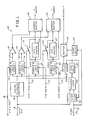
- Figure 1 illustrates a graphics symbol generator 10.
- Digital data representing the parameters x-start position, y-start position, sin ⁇ , cos ⁇ and length of a line to be drawn on the face of a CRT is provided from an external microprocessor (not shown) on a data bus 11.
- the parameter is converted to analogue form by a digital-to-analogue (D/A) converter 12 and simultaneously the corresponding strobe-pulse (STB) enables a sample and hold circuit for that parameter.
- D/A digital-to-analogue
- STB strobe-pulse
- the strobe-pulse appearing on a lead 13 enables sample and hold circuit 14, which samples and holds the converted analogue signal of the x-start position appearing at the output of the D/A converter 12.
- a strobe-pulse appearing on a lead 15 enables a sample and hold circuit 16 to retain the analogue representation of the y-start position
- strobe-pulses appearing on leads 17 and 19 enable sample and hold circuits 18 and 20 to hold analogue representations sin ⁇ and cos ⁇ information, respectively.
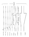
- the timing of the four strobe-pulses is depicted in Figure 2. Length data is provided in digital form from the external microprocessor to a counter/latch 33.
- the external microprocessor places a start pulse on a lead 31, which pulse initiates three simultaneous actions; a flip flop 32 is set, thereby causing the counter/latch 33 to begin decrementing the length value previously entered from data bus 11; a start delay 37 begins timing, thereby keeping the intensity blanked a predetermined length of time as illustrated in Figure 2, and starts to count down the predetermined delay; a flip flop 35 is set, thereby opening switches 23 and 26 which enable the sweep signals.
- a portion of the sin ⁇ value from the sample and hold circuit 18 is fed around an integrator 24 to a summer/buffer 29 which effectively causes the x-start position, applied to the summer/buffer 29 from the sample and hold circuit 14 through an inverter 21, to back-up along the axis of the line to be drawn.
- the switch 23 is opened, the integrated value of sin ⁇ at the output of the integrator 24 is supplied to the summer/buffer 29, thereby moving the x-start position along the axis of the line to be drawn towards the original x-start position.
- the output of the summer/buffer 29 is the x-sweep signal as illustrated in Figure 2.
- a portion of the cos ⁇ value from the sample and hold circuit 20 is fed around an integrator 27 to a summer/buffer 30 to back-up the y-start position along the axis of the line to be drawn.
- the y-start position value is provided to the summer/buffer 30 from the output of the sample and hold circuit 16 through an inverter 22.
- the switch 26 When the switch 26 is opened, the integrated value of cos ⁇ appearing at the output of integrator 27 is provided to the summer/buffer 30 where it is summed with the portion of cos ⁇ provided directly to the summer/buffer 30 and the y-start position value.
- the output of summer/buffer 30 is the y-sweep signal.
- the start delay 37 times out and enables the intensity.
- the desired start of the line to be drawn becomes visible on the face of the CRT.
- the desired line is then drawn by the x-sweep and y-sweep signals applied to the deflection coils of the CRT in accordance with the x-start position, y-start position, cos ⁇ , sin ⁇ and length parameters supplied by the associated microprocessor.
- the counter/latch 33 When the counter/latch 33 has decremented the desired line length to zero, it outputs a pulse to a stop delay 34 which has the same amount of delay as the start delay 37.
- the stop delay 34 times out, the flip flop 35 is reset, thereby inhibiting the intensity and causing the switches 23 and 26 to close.
- the output of the stop delay 34 also resets the flip flop 32.
- the present invention achieves a reduction in distortion of graphic symbols by starting the x-sweep and y-sweep a predetermined time before the intensity is enabled.
- a counter/latch after decrementing the desired length, initiates a stop delay which disables the intensity after a predetermined time. Start and stop delays having the same delay time result in the desired line length being visible on the CRT.
Landscapes
- Engineering & Computer Science (AREA)
- Radar, Positioning & Navigation (AREA)
- Remote Sensing (AREA)
- Physics & Mathematics (AREA)
- Computer Hardware Design (AREA)
- General Physics & Mathematics (AREA)
- Theoretical Computer Science (AREA)
- Manufacture Of Electron Tubes, Discharge Lamp Vessels, Lead-In Wires, And The Like (AREA)
- Testing, Inspecting, Measuring Of Stereoscopic Televisions And Televisions (AREA)
- Controls And Circuits For Display Device (AREA)
- Details Of Television Scanning (AREA)
- Radar Systems Or Details Thereof (AREA)
Applications Claiming Priority (2)
| Application Number | Priority Date | Filing Date | Title |
|---|---|---|---|
| US06/765,754 US4724432A (en) | 1985-08-15 | 1985-08-15 | Generation of graphic symbols for cathode ray tube displays |
| US765754 | 2001-01-19 |
Publications (2)
| Publication Number | Publication Date |
|---|---|
| EP0211544A2 true EP0211544A2 (fr) | 1987-02-25 |
| EP0211544A3 EP0211544A3 (fr) | 1990-03-28 |
Family
ID=25074396
Family Applications (1)
| Application Number | Title | Priority Date | Filing Date |
|---|---|---|---|
| EP86305464A Withdrawn EP0211544A3 (fr) | 1985-08-15 | 1986-07-16 | Génération de symboles graphiques pour des dispositifs de visualisation à TRC |
Country Status (7)
| Country | Link |
|---|---|
| US (1) | US4724432A (fr) |
| EP (1) | EP0211544A3 (fr) |
| JP (1) | JPS6239890A (fr) |
| CA (1) | CA1252578A (fr) |
| DK (1) | DK372386A (fr) |
| ES (1) | ES2001229A6 (fr) |
| NO (1) | NO863057L (fr) |
Families Citing this family (1)
| Publication number | Priority date | Publication date | Assignee | Title |
|---|---|---|---|---|
| JPS5730924A (en) * | 1980-08-02 | 1982-02-19 | Kokusai Keisokki Kk | Device for automatically positioning unbalanced point |
Family Cites Families (7)
| Publication number | Priority date | Publication date | Assignee | Title |
|---|---|---|---|---|
| US3482086A (en) * | 1967-06-30 | 1969-12-02 | Raytheon Co | Constant writing rate vector generator |
| US4001806A (en) * | 1976-01-07 | 1977-01-04 | United Technologies Corporation | Deflection signal pre-start circuit for a constant speed, stroke-write vector display system |
| US4237458A (en) * | 1979-06-25 | 1980-12-02 | International Business Machines Corporation | Stroke expansion apparatus |
| DE3174607D1 (en) * | 1980-04-02 | 1986-06-19 | Gec Avionics | Signal generating arrangements |
| US4369441A (en) * | 1980-09-18 | 1983-01-18 | Louis Wohlmuth | Display control system |
| US4535328A (en) * | 1982-09-13 | 1985-08-13 | Rockwell International Corporation | Digitally controlled vector generator for stroke written CRT displays |
| US4595918A (en) * | 1983-09-02 | 1986-06-17 | Sperry Corporation | Stroke writing character generator with reduced bandwidth |
-
1985
- 1985-08-15 US US06/765,754 patent/US4724432A/en not_active Expired - Fee Related
-
1986
- 1986-05-28 JP JP61123192A patent/JPS6239890A/ja active Pending
- 1986-07-16 EP EP86305464A patent/EP0211544A3/fr not_active Withdrawn
- 1986-07-28 NO NO863057A patent/NO863057L/no unknown
- 1986-08-05 DK DK372386A patent/DK372386A/da not_active Application Discontinuation
- 1986-08-14 CA CA000515941A patent/CA1252578A/fr not_active Expired
- 1986-08-14 ES ES8601117A patent/ES2001229A6/es not_active Expired
Also Published As
| Publication number | Publication date |
|---|---|
| EP0211544A3 (fr) | 1990-03-28 |
| US4724432A (en) | 1988-02-09 |
| JPS6239890A (ja) | 1987-02-20 |
| DK372386A (da) | 1987-02-16 |
| CA1252578A (fr) | 1989-04-11 |
| DK372386D0 (da) | 1986-08-05 |
| NO863057L (no) | 1987-02-16 |
| NO863057D0 (no) | 1986-07-28 |
| ES2001229A6 (es) | 1988-05-01 |
Similar Documents
| Publication | Publication Date | Title |
|---|---|---|
| US4212009A (en) | Smoothing a raster display | |
| US4799165A (en) | Level detecting waveform sampling system | |
| US4528591A (en) | Raster scan frame digitizer method and apparatus | |
| US4251814A (en) | Time dot display for a digital oscilloscope | |
| US4149252A (en) | Digital ρ-θ to XY scan converter for use with limited access or random access reiteration memory | |
| EP0088568B1 (fr) | Générateur de vecteur d'affichage utilisant l'accumulation de sinus/cosinus | |
| US4222106A (en) | Functional curve displaying process and apparatus | |
| US4739277A (en) | Triggered, programmable skew signal generator | |
| EP0211544A2 (fr) | Génération de symboles graphiques pour des dispositifs de visualisation à TRC | |
| US4560981A (en) | Logic waveform display apparatus | |
| US4974058A (en) | Color signal processing apparatus using a plurality of sample-and-hold circuits and a single switched A/D converter | |
| US4851922A (en) | Video signal processing apparatus | |
| US4484189A (en) | Memoryless artificial horizon generator | |
| EP0004152A1 (fr) | Conversion digitale d'un signal analogique périodique | |
| US3984664A (en) | Digital system for generating a circle on a raster type television display | |
| US3980926A (en) | Spiral scan display apparatus with transient suppression means | |
| US4724421A (en) | Time interval to digital converter with smoothing | |
| US3413453A (en) | Hybrid ramp function generator to deflect electron beam | |
| DE2400424A1 (de) | System zur verarbeitung und wiedergabe von information wie oszillograph o. dgl | |
| GB1067837A (en) | A circuit arrangement for producing a completion signal after completion of a process of variable duration | |
| US4059785A (en) | CRT display with truncated Rho-Theta presentation | |
| US4801851A (en) | Oscilloscope memory control | |
| JPH0571103B2 (fr) | ||
| SU1037327A1 (ru) | Устройство дл отображени информации на экране электронно-лучевой трубки | |
| SU1037328A1 (ru) | Устройство дл отображени графической информации |
Legal Events
| Date | Code | Title | Description |
|---|---|---|---|
| PUAI | Public reference made under article 153(3) epc to a published international application that has entered the european phase |
Free format text: ORIGINAL CODE: 0009012 |
|
| AK | Designated contracting states |
Kind code of ref document: A2 Designated state(s): DE FR GB IT NL SE |
|
| RAP1 | Party data changed (applicant data changed or rights of an application transferred) |
Owner name: SPERRY MARINE INC. |
|
| PUAL | Search report despatched |
Free format text: ORIGINAL CODE: 0009013 |
|
| AK | Designated contracting states |
Kind code of ref document: A3 Designated state(s): DE FR GB IT NL SE |
|
| 17P | Request for examination filed |
Effective date: 19900917 |
|
| STAA | Information on the status of an ep patent application or granted ep patent |
Free format text: STATUS: THE APPLICATION HAS BEEN WITHDRAWN |
|
| 18W | Application withdrawn |
Withdrawal date: 19911031 |
|
| R18W | Application withdrawn (corrected) |
Effective date: 19911031 |
|
| RIN1 | Information on inventor provided before grant (corrected) |
Inventor name: CORNETT, JOHNNY ALLAN Inventor name: BEAZELL, THOMAS GARDNER |