EP0211227A2 - Warnvorrichtung - Google Patents
Warnvorrichtung Download PDFInfo
- Publication number
- EP0211227A2 EP0211227A2 EP86108880A EP86108880A EP0211227A2 EP 0211227 A2 EP0211227 A2 EP 0211227A2 EP 86108880 A EP86108880 A EP 86108880A EP 86108880 A EP86108880 A EP 86108880A EP 0211227 A2 EP0211227 A2 EP 0211227A2
- Authority
- EP
- European Patent Office
- Prior art keywords
- lights
- user
- substrate
- illuminating
- clock pulse
- Prior art date
- Legal status (The legal status is an assumption and is not a legal conclusion. Google has not performed a legal analysis and makes no representation as to the accuracy of the status listed.)
- Withdrawn
Links
- 239000000758 substrate Substances 0.000 claims abstract description 14
- 239000003086 colorant Substances 0.000 claims abstract 2
- 239000000463 material Substances 0.000 description 3
- 239000003990 capacitor Substances 0.000 description 2
- 229920003023 plastic Polymers 0.000 description 2
- 239000004033 plastic Substances 0.000 description 2
- 230000001419 dependent effect Effects 0.000 description 1
- 238000010586 diagram Methods 0.000 description 1
- 231100001261 hazardous Toxicity 0.000 description 1
Images

Classifications
-
- G—PHYSICS
- G08—SIGNALLING
- G08B—SIGNALLING OR CALLING SYSTEMS; ORDER TELEGRAPHS; ALARM SYSTEMS
- G08B5/00—Visible signalling systems, e.g. personal calling systems, remote indication of seats occupied
- G08B5/006—Portable traffic signalling devices
-
- F—MECHANICAL ENGINEERING; LIGHTING; HEATING; WEAPONS; BLASTING
- F21—LIGHTING
- F21L—LIGHTING DEVICES OR SYSTEMS THEREOF, BEING PORTABLE OR SPECIALLY ADAPTED FOR TRANSPORTATION
- F21L2/00—Systems of electric lighting devices
Definitions
- THIS INVENTION relates to a warning device, in particular a warning device for indicating the presence of a wearer to motorists at night and in conditions of bad visibility.
- Pedestrians and cyclists, particularly children, using the roads at night or in conditions of bad visibility may be very difficult for a motorist to see, particularly if they are wearing dark clothing. Although the public is advised to wear something light at night and fluroscent or reflective bands jackets etc are available, a motorist may still not spot a pedestrian or cyclist wearing such clothing until the headlamps of his car actually shine on the pedestrian or cyclist.
- a warning device for indicating the presence of a wearer thereof to motorists at night and in conditions of bad visibility, the device comprising a substrate provided with a plurality of lights and adapted to be worn by a user of the device, and means for illuminating the lights.
- warning device embodying the invention for indicating the presence of a wearer thereof to motorists, particularly at night and in conditions of bad visibility.
- the device comprises a substrate 1 in the form of an endless transparent tube adapted to be worn diagonally across the user's body as shown in Figures 3A and 3B.
- the substrate may alternatively take form of a jacket or belt or any other suitable form of clothing.
- the substrate 1 which may be made of a plastics material and may advantageously be fluorescent or reflective has a plurality of lights 2 positioned spaced apart along the length thereof.
- the lights 2 thereof which are preferably 3 to 6 volt 60 milliamp bulbs are electrically connectable to an illuminating means in the form of a rechargeable battery (not shown) carried within a portable casing 3.
- the portable casing 3 is formed of a plastics material and is sized so as to be received in a pocket of the user's clothing or is arranged to be hooked onto a user's belt.
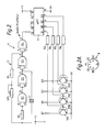
- the warning device also includes control means 4 for causing the lights to flash on and off in a predetermined manner.
- the control means 4 controls an oscillator circuit 5 for supplying a clock signal to the clock input pin 13 of a CMOS 74 nc 4017 10-stage Johnson counter integrated circuit 6.
- the oscillator circuit 5 comprises four 2-input NAND gates G1 to G4 in the form of a 4093 Quad Schmit NAND gate integrated circuit, each NAND gate having their two inputs coupled together.
- the four NAND gates are connected in series and the output of the second NAND gate G2 is fed back via a 0.47 uf capacitor C1 and a 2.2 megaohm resistor R2 to the coupled inputs of the first NAND gate G1.
- the output of the third NAND gate G3 is fed back via a 220 kilo-ohm resistor R1, a variable resistor VR1 of nominal resistance 1 megaohm and the resistor R2 to the coupled inputs of the first NAND gate G1.
- the output of the fourth NAND gate G4 is supplied as the clock signal to the clock input pin 13 of the integrated circuit 6.
- the values of the resistors of R1 and R2 and the capacitor C1 are selected and the variable resistor is normally set so that a clock pulse is supplied once every 64 milliseconds to provide a 15.625 Hz clock pulse signal to the integrated circuit 6.
- the frequency of the clock pulse signal may be varied to vary the rate at which the lights flash by varying the resistance of the variable resistor VR1 via a control which may be internal or may include an external control knob 7 provided on the casing 3.
- the integrated circuit 6 In response to the clock signal from the oscillator circuit 5, the integrated circuit 6 delivers four output signals Q1, Q0, Q2 and Q3 which are spaced apart by a predetermined time which may be determined by the clock pulse signal.
- the frequency of the output signals Q0 to Q3 is, of course, dependent upon the frequency of the clock pulse signal input to the integrated circuit 6.
- Each of the output signals Q1, Q0, Q2 and Q3 is supplied via a respective 1 kilo-ohm resistor R3, R4, R5 and R6 to the base of a respective NPN transistor TR1, TR0, TR2 and TR3 of type BC 184, the emitters of which are connected to the 0 volt power supply line, that is the negative terminal of the rechargable battery (not shown).
- each transistor TR1, TR0, TR2 and TR3 is connected to a respective pin Q1, Q0, Q2 and Q3 of a five pin DIN socket 8 mounted in the casing 3.
- the positive terminal V+ of the battery (not show) is connected to a centre pin of the DIN socket 8 via a switch 9 which may be manually operated by a user of the device to connect the battery in circuit.
- the lights 2 are connected to a five-pin DIN plug 10 corresponding to the socket 8 so that when the plug 10 is received in the socket 8, each light 2 is connected to the V+ pin of the socket 8 and also to a respective one of the pins Q0 to Q3.
- the lights are connected so that, starting from the plug 10, every fourth light is connected to the same pin of the plug.
- the first, fifth, ninth, etc. lights are connected to one pin
- the second, sixth, tenth, etc. lights are connected to a second pin
- the third, seventh, eleventh, etc. lights are connected to a third pin
- the fourth, eight, twelfth, etc. lights are connected to a fourth pin of the plug 10.
- connections for the lights to the DIN plug 10 may be provided.
- Preferably differently coloured lights 2 are used and are arranged so that when the band or substrate is worn by a user as shown in Figures 3A and 3B, lights of a first colour are adjacent the user's as chest and lights of a second colour are adjacent the user's back.
- the lights adjacent the user's chest are white lights and the lights adjacent the user's back are red lights.
- the battery (not shown) is rechargeable and a charging lead 11 for connection via a transformer to a mains power supply or to a specially adapted charging unit is provided, the charging lead 11 having a jack plug 12 for reception in a corresponding socket 13 provided in the casing 3.
- the casing 3 is preferably sized so as to be able to be hooked on a belt of a user or received within a pocket of the user's clothing.
- the casing 3 is rectangular and is 6 inches (15cm) long, 3 inches (7.5cm) wide and 11 ⁇ 4 inch (3 cm) deep.
- a waist belt may be provided to secure the tube 1 in position on a wearer's body.
- the warning device is particulary suited for earning motorists of the present or cyclist wearing the device
- the warning device may also be used in daylight by the front and back markers of a large group of people walking along a road. Workers in hazardous situations such as road and railway workers may also find such a device useful.
Landscapes
- Business, Economics & Management (AREA)
- Emergency Management (AREA)
- Physics & Mathematics (AREA)
- General Physics & Mathematics (AREA)
- Engineering & Computer Science (AREA)
- General Engineering & Computer Science (AREA)
- Professional, Industrial, Or Sporting Protective Garments (AREA)
- Outerwear In General, And Traditional Japanese Garments (AREA)
Applications Claiming Priority (2)
| Application Number | Priority Date | Filing Date | Title |
|---|---|---|---|
| GB08519629A GB2178838B (en) | 1985-08-05 | 1985-08-05 | A warning device |
| GB8519629 | 1985-08-05 |
Publications (2)
| Publication Number | Publication Date |
|---|---|
| EP0211227A2 true EP0211227A2 (de) | 1987-02-25 |
| EP0211227A3 EP0211227A3 (de) | 1988-10-26 |
Family
ID=10583333
Family Applications (1)
| Application Number | Title | Priority Date | Filing Date |
|---|---|---|---|
| EP86108880A Withdrawn EP0211227A3 (de) | 1985-08-05 | 1986-06-30 | Warnvorrichtung |
Country Status (2)
| Country | Link |
|---|---|
| EP (1) | EP0211227A3 (de) |
| GB (1) | GB2178838B (de) |
Cited By (3)
| Publication number | Priority date | Publication date | Assignee | Title |
|---|---|---|---|---|
| GB2228074A (en) * | 1989-02-10 | 1990-08-15 | Joyce Beatrice Rudham | Hazard warning device |
| EP0432201A4 (en) * | 1988-09-01 | 1992-06-03 | Alliko Unlimited Corp. | Illuminated article and waterproof illuminated harness |
| ES2191567A1 (es) * | 2002-02-25 | 2003-09-01 | Ayala Rodrigo Martin | Sistema de señalizacion vial luminosa portatil. |
Families Citing this family (1)
| Publication number | Priority date | Publication date | Assignee | Title |
|---|---|---|---|---|
| US5779348A (en) * | 1997-02-18 | 1998-07-14 | Interlicchio; Joseph C. | Illuminated safety shoulder strap |
Family Cites Families (9)
| Publication number | Priority date | Publication date | Assignee | Title |
|---|---|---|---|---|
| FR1282993A (fr) * | 1960-03-12 | 1962-01-27 | Appareil de signalisation lumineux adaptable à la main, convenant en particulier aux cyclistes et motocyclistes | |
| GB1010632A (en) * | 1960-10-17 | 1965-11-24 | Tadahichi Wada | Improvements in or relating to hand-operable electrical lighting devices |
| GB960837A (en) * | 1961-03-16 | 1964-06-17 | Raymond Douglas Plumb | Improvements in or relating to gloves |
| FR93881E (fr) * | 1967-02-22 | 1969-05-30 | Philippe Altare | Dispositif pour la signalisation visuelle de son utilisateur. |
| US3641333A (en) * | 1968-12-05 | 1972-02-08 | Everett W Gendron | Illuminated belt |
| US4173201A (en) * | 1977-08-30 | 1979-11-06 | Albert Chao | Illuminated collar for pets and the like |
| US4238709A (en) * | 1978-07-05 | 1980-12-09 | Wallace John M | Head lamp control circuit |
| DE3302981A1 (de) * | 1983-01-29 | 1984-08-02 | Adolf Nissen Elektrobau GmbH & Co KG, 2253 Tönning | Richtungsweisende lauflichtanlage |
| US4523258A (en) * | 1983-09-19 | 1985-06-11 | Morse John H | Flexible safety belt with flashing light-emitting devices and alarm |
-
1985
- 1985-08-05 GB GB08519629A patent/GB2178838B/en not_active Expired
-
1986
- 1986-06-30 EP EP86108880A patent/EP0211227A3/de not_active Withdrawn
Cited By (4)
| Publication number | Priority date | Publication date | Assignee | Title |
|---|---|---|---|---|
| EP0432201A4 (en) * | 1988-09-01 | 1992-06-03 | Alliko Unlimited Corp. | Illuminated article and waterproof illuminated harness |
| GB2228074A (en) * | 1989-02-10 | 1990-08-15 | Joyce Beatrice Rudham | Hazard warning device |
| GB2228074B (en) * | 1989-02-10 | 1992-02-12 | Joyce Beatrice Rudham | Hazard warning device |
| ES2191567A1 (es) * | 2002-02-25 | 2003-09-01 | Ayala Rodrigo Martin | Sistema de señalizacion vial luminosa portatil. |
Also Published As
| Publication number | Publication date |
|---|---|
| EP0211227A3 (de) | 1988-10-26 |
| GB8519629D0 (en) | 1985-09-11 |
| GB2178838A (en) | 1987-02-18 |
| GB2178838B (en) | 1989-01-11 |
Similar Documents
| Publication | Publication Date | Title |
|---|---|---|
| US5613756A (en) | Clothing with pouch means for receiving an illuminating device | |
| US5879076A (en) | Method and appartus for light transmission | |
| US6106130A (en) | Personal lighted and reflective safety system with shoulder straps for pedestrians | |
| US5070436A (en) | Signal vest, colored, reflective, and lighted, worn by persons seen on and nearby roadways and highways and other needed areas | |
| EP1090252B1 (de) | Verfahren und vorrichtung zur übertragung des lichtes | |
| US4812953A (en) | Safety light band | |
| US5690411A (en) | Wearable vehicular signaling system adapted and augmented for wearing on or about the body of a person | |
| US5980060A (en) | Portable object having a fastening band illuminated by a super thin light element | |
| US6104313A (en) | Portable automated flagman | |
| US4328533A (en) | Illuminated safety garment | |
| WO2003015551B1 (en) | Safety signal jacket for riders of non-enclosed vehicles | |
| US5779348A (en) | Illuminated safety shoulder strap | |
| US3134548A (en) | Safety belt | |
| AU2003215432A1 (en) | Methods and apparatus relating to improved visual recognition and safety | |
| US8144030B1 (en) | Personal signal device with automatic switching based on orientation | |
| US20170151989A1 (en) | Wearable LED warning light a safety device and turn signal lights utility belt | |
| EP0086651A2 (de) | Tragbare Warnvorrichtung | |
| EP0211227A2 (de) | Warnvorrichtung | |
| US3321617A (en) | Snap on night protector | |
| US6715897B2 (en) | Illuminated hand signal | |
| US20170122506A1 (en) | Personal Safety Light | |
| US7401937B2 (en) | Traffic gloves | |
| US11291259B1 (en) | Attachable decorative medallion for cap | |
| RU189212U1 (ru) | Сигнальный жилет | |
| GB2228512A (en) | Personal trafficator/hazard warning system |
Legal Events
| Date | Code | Title | Description |
|---|---|---|---|
| PUAI | Public reference made under article 153(3) epc to a published international application that has entered the european phase |
Free format text: ORIGINAL CODE: 0009012 |
|
| AK | Designated contracting states |
Kind code of ref document: A2 Designated state(s): AT BE CH DE FR GB IT LI LU NL SE |
|
| PUAL | Search report despatched |
Free format text: ORIGINAL CODE: 0009013 |
|
| AK | Designated contracting states |
Kind code of ref document: A3 Designated state(s): AT BE CH DE FR GB IT LI LU NL SE |
|
| STAA | Information on the status of an ep patent application or granted ep patent |
Free format text: STATUS: THE APPLICATION IS DEEMED TO BE WITHDRAWN |
|
| 18D | Application deemed to be withdrawn |
Effective date: 19890427 |