EP0210824B1 - Heel seat lasting machine - Google Patents
Heel seat lasting machine Download PDFInfo
- Publication number
- EP0210824B1 EP0210824B1 EP19860305627 EP86305627A EP0210824B1 EP 0210824 B1 EP0210824 B1 EP 0210824B1 EP 19860305627 EP19860305627 EP 19860305627 EP 86305627 A EP86305627 A EP 86305627A EP 0210824 B1 EP0210824 B1 EP 0210824B1
- Authority
- EP
- European Patent Office
- Prior art keywords
- shoe
- arrangement
- heel
- heel seat
- toe
- Prior art date
- Legal status (The legal status is an assumption and is not a legal conclusion. Google has not performed a legal analysis and makes no representation as to the accuracy of the status listed.)
- Expired
Links
Images


Classifications
-
- A—HUMAN NECESSITIES
- A43—FOOTWEAR
- A43D—MACHINES, TOOLS, EQUIPMENT OR METHODS FOR MANUFACTURING OR REPAIRING FOOTWEAR
- A43D21/00—Lasting machines
- A43D21/12—Lasting machines with lasting clamps, shoe-shaped clamps, pincers, wipers, stretching straps or the like for forming the toe or heel parts of the last
-
- A—HUMAN NECESSITIES
- A43—FOOTWEAR
- A43D—MACHINES, TOOLS, EQUIPMENT OR METHODS FOR MANUFACTURING OR REPAIRING FOOTWEAR
- A43D119/00—Driving or controlling mechanisms of shoe machines; Frames for shoe machines
-
- A—HUMAN NECESSITIES
- A43—FOOTWEAR
- A43D—MACHINES, TOOLS, EQUIPMENT OR METHODS FOR MANUFACTURING OR REPAIRING FOOTWEAR
- A43D21/00—Lasting machines
- A43D21/14—Lasting machines for toe or heel parts, with nailing devices
Description
- This invention is concerned with heel seat lasting machines comprising a shoe support for supporting bottom uppermost a shoe comprising an upper on a last and an insole on the last bottom, heel seat lasting instrumentalities, including a heel band and a pair of wiper plates together with drive means for moving the wiper plates forwardly and inwardly into an advanced position determined by a stroke limiting arrangement, during which movement lasting marginal portions of the shoe upper in the heel seat region thereof are wiped over and pressed by the wiper plates against corresponding marginal portions of the insole, and fastener-inserting means associated with the wiper plates whereby, with the wiper plates in their advanced position, fasteners can be inserted through the lasting marginal portions of the upper into the insole thus to secure said portions to the insole, wherein setting means is provided whereby both the stroke limiting arrangement is set according to the desired advanced position of the wiper plates and also the position of the heel band, lengthwise of the shoe bottom, is set so as to position the heel seat of a shoe supported by the shoe support in a desired relationship with the wiper plates, and thus with the fastener-inserting means, and further wherein means is provided, including two shoe-engaging members arranged one at each side of the shoe support, for orienting the heel seat region of the shoe bottom in a desired relationship with the longitudinal centre line of the heel seat lasting instrumentalities.
- One such machine is described in GB-A 2091535. More particularly, the heel seat lasting machine there described is arranged in combination with apparatus for moving successive shoe supports from a loading station to a plurality of operating stations, including one at which the heel seat lasting machine. is disposed. The combination as a whole thus enables shoes to be processed automatically through side lasting and heel seat lasting operations, requiring only a single operator for loading and unloading shoes on the shoe supports.
- The heel seat lasting machine forming part of the combination is, as stated in the specification, generally similar to the machine described in GB-A 2052950, in which specification constructional details of the machine are described. Thus, in said machine the setting means comprises first manually operable means for positioning the stroke limiting arrangement and second manually operated means for setting the position of the heel band. Furthermore, because of the particular construction of the machine each time the position of the stroke limiting arrangement is altered, the relationship between the back seam region of the heel seat of the shoe and those parts of the fastener-inserting means which drive in the so-called "back tacks" is varied, so that in general it is also necessary to alter the position of the heel band.
- It has been proposed in EP-A 58471 to vary the position of the heel band in consequence of any variation of the setting of the stroke limiting arrangement. However, this still requires the manual setting of the stroke limiting arrangement to accommodate each size of shoe.
- It will be appreciated that while manual settings have to be made, the machine does not lend itself to fully automatic operation.
- It is the object of the present invention to provide an improved heel seat lasting machine in which the various settings referred to are achieved wholly automatically, so that the operator has merely to load and unload shoes on the shoe support.
- In accordance with the present invention this object is resolved, in a machine as set out in the first paragraph above, in that the setting means is operated to effect such setting of the stroke limiting arrangement and of the heel band position in response to a signal generated according to the distance moved by the shoe-engaging members in orienting the heel seat region of the shoe as aforesaid, and thus according to the width of the shoe in the region thereof engaged by said members.
- It will thus be appreciated that, in using the machine in accordance with the present invention, the heel band position and the stroke limiting arrangement can be set in accordance with the width of the shoe by the utilisation of the orienting means. Thus, the orienting means ensures that the shoe is located correctly in relation to the heel seat lasting instrumentalities, and at the same time the heel seat lasting instrumentalities are properly set according to . the shoe dimensions. In this way the settings of the machine and the positioning of the shoe are achieved without interference from the operator, and indeed without significant additional equipment being required in the machine construction.
- Conveniently the setting means comprises a servomotor which is operated to effect such setting in response to said signal. It will thus be appreciated that any suitable means for providing a signal can be utilised, and in particular an electrical or electronic signalling arrangement is favoured.
- In the machine disclosed in GB-A 2052950 the drive means comprises a fluid pressure operated motor with which is associated an abutment cooperable with the stroke limiting arrangement thus to determine the advanced position of the wiper plates. In the machine in accordance with the present invention, furthermore, preferably the servomotor is effective to position a stop member serving to limit pivotal movement of a lever which is connected to the stroke limiting arrangement and pivotal movement of which is thus effective to move said arrangement as aforesaid. By this mechanical linkage arrangement, it will be seen that a single servomotor may be utilised for positioning the heel band and for setting the stroke limiting arrangement, since the relationship between the degrees of movement of each can be achieved through the mechanical system by which the one setting, in this case that of the stroke limiting arrangement, is effected.
- Furthermore, in a preferred embodiment the stop member is operatively connected to the servomotor by a Bowden cable and a locking arrangement is provided for locking the stop member in its adjusted position. In this way a remote connection can readily be achieved between the heel band and the stroke limiting arrangement, while preserving a single servomotor for effecting setting of each.
- In GB-A 2092430 is described a modificaton of the machine as disclosed in DE-A 2052950, in which modification the wiper plates are positioned, initially in a machine cycle, in an intermediate position. In this intermediate position the wiper plates are so positioned that, as the shoe is moved into engagement with the heel band, the leading edges of the wiper plates just traverse over the margin of the shoe bottom and thus provide an abutment by which the heightwise position of the shoe bottom can be determined. This is seen as advantageous in that firstly it is no longer necessary to provide a presser foot at the operating locality of the machine, and secondly, because the leading edges of the wiper plates engage the shoe bottom in the region over which they will subsequently operate to effect a lasting operation, the shoe bottom is properly oriented both lengthwise and widthwise by the use of the wiper plates in this manner.
- In the machine in accordance with the invention, therefore, preferably the setting means comprises a signalling device for generating a signal by which the initial operation of the drive means is controlled to bring the wiper plates to said intermediate position, said signalling device being itself actuated according to the distance moved by the shoe-engaging members in orienting the heel seat region of the shoe as aforesaid, and thus according to the width of the shoe in the region thereof engaged by said members. More particularly, in a preferred embodiment the signalling device comprises a switch-and-actuator arrangement associated with the drive means, and the servomotor, when operated as aforesaid, is effective to cause said arrangement to be moved into a de-actuated condition, thus causing said signal to be generated to operate the drive means to return said arrangement to an actuated condition, and thus to move the wiper plates to their intermediate position. It will thus be appreciated that this further setting is now automatically achieved, and indeed by the use of the single servomotor acting through a linkage arrangement which affords the necessary proportionality of movement of the signalling device in relation to that of the stroke limiting arrangement.
- Conveniently, the signal in response to which the setting means is operated as aforesaid is also generated by a signalling device comprising a switch-and-actuator arrangement operatively connected to the shoe-engaging members of the orienting means, the movement of said members in orienting the heel seat of the shoe as aforesaid being effective to cause said arrangement to be moved into a de-actuated condition, thus causing said signal to be generated to operate the setting means to return said arrangement to an actuated condition, and thus to set the stroke limiting arrangement and the heel band position as aforesaid. It will of course be appreciated that, instead of such an arrangement, it would be possible to utilise e.g. a linear potentiometer by which the distance moved by the shoe-engaging members could be monitored, such potentiometer feeding a signal to the servomotor.
- In the machine described in GB-A 2052950 the shoe support is movable into and out of an operative position, in which the heel end of a shoe supported thereby is engagable with the heel band. In the machine of GB-A 2091535, on the other hand, the shoe support is fixed and the whole of the operating parts of the heel seat lasting machine is movable bodily towards and away from the shoe support. Whichever system is utilised, from the teaching of GB-A 2091535 it is clear that the shoe is oriented only after it has been received in the heel band, that is to say after it has reached the operating locality of the machine. It will of course be clear that such an arrangement would be disadvantageous in the context of the present invention, in accordance with which, therefore, preferably, the orienting means and the setting means are operable as aforesaid prior to movement of the shoe support into its operative position. In particular by this arrangement the setting of the various integers of the machine can take place before the shoe is moved into the heel band, such prior setting being of course only achievable if the shoe is previously oriented and its width measured.
- Conventionally in heel seat lasting machines a holddown is provided engagable with the heel seat of a shoe supported by the support for clamping the shoe on the latter. In accordance with the present invention, furthermore, preferably the holddown, which comprises three contact points for engagement with the shoe bottom thus to orient the plane of the heel seat of the shoe in a desired plane, engages the shoe bottom in the heel seat region thereof prior to operation of the orienting means. It will be appreciated that, by virtue of a holddown of the aforementioned construction engaging the shoe prior to the operation of the orienting means, the plane of the heel seat is oriented prior to the engagement of the shoe by the shoe-engaging members of the orienting means, so that the setting means is caused to operate as aforesaid only after the shoe has been positioned, so far as concerns the plane of its heel seat, appropriately for the heel seat lasting operation.
- In the machine disclosed in GB-A 2091535 the shoe support comprises a toe rest which is moveable in a direction heightwise of the shoe, the arrangement being such that in the operation of the machine it is first moved in said lengthwise direction beneath the shoe toe, until arrested by the engagement of an upstanding abutment portion thereof with the toe, and is then moved heightwise into a position of contact with the shoe toe thus to support the toe end of the shoe. In accordance with the present invention, furthermore, preferably the toe rest is rockable about an axis extending lengthwise of the shoe in one or other direction according to whether the shoe supported thereby is a left or a right, and in that a signalling device is associated with the toe rest and is actuated in response to rocking movement of the toe rest, generating a signal indicating the presence of a left or a right shoe. This signal may have a variety of uses, one of which is to cause heightwise movement of the toe rest to be discontinued and, if desired, to cause the toe rest to be locked in the position to which it has been so moved.
- There now follows a detailed description, to be read with reference to the accompanying drawings, of one machine in accordance with the invention. This machine, it will be appreciated, has been selected for description merely by way of non-limiting example of the invention.
- In the accompanying drawings:-
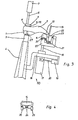
- Figs. 1 to 3 show, in diagrammatic form, a side view of a shoe support of the machine in its loading position, indicating various stages in the movement of a toe rest of the support to engage the toe end of the shoe;
- Fig. 4 is a fragmentary view showing details of the toe rest;
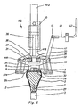
- Fig. 5 is fragmentary view indicating the action of orienting means in relation to a shoe supported by the shoe support; and
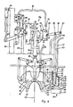
- Fig. 6 is a fragmentary plan view of the machine, showing details of heel seat lasting instrumentalities and setting means thereof.
- The machine now to be described is generally similar, accepted as hereinafter described, to the machine described in GB-A 2052950, but modified as set out in GB-A 2092430, and comprises a shoe support generally designated 110 for supporting, bottom up, a
shoe 2 on a last 1, with an insole on the last bottom. In general, it will be expected that the toe region of the shoe will already have been lasted. Theshoe support 110 comprises a heel end support comprising alast pin 27 carried on alast post 3 which is mounted for heightwise movement in a casting 4. The casting 4 is mounted for pivotal movement about a transverse axis (not shown) to move the shoe support bodily into and out of an operative position in which the heel seat of the shoe is located at an operating locality of the machine. - For setting the heightwise position of the heel end of the shoe, while the
shoe support 110 remains in a loading position spaced from the operative position, aholddown 5 is arranged in opposed relationship with thelast post 3, said holddown being mounted, by means (not shown), for movement with theshoe support 110 between loading and operative positions. The holddown is secured at the end of apiston rod 6 of a piston-and-cylinder arrangement 7 for movement between advanced and retracted conditions. When the last 1 is placed on thepin 27, thepiston rod 6 is in its retracted condition to facilitate loading. It is thereafter moved to its advanced condition (see Fig. 1) and is locked in that condition, thereby setting a height datum for the heel end of the shoe. With theholddown 5 thus locked, thelast post 3 is then moved heightwise to bring theheel seat 28 of theshoe 2 into engagement with theholddown 5, thereby positioning it at the height datum. - The
holddown 5 comprises threeprojections 8, 9 and 10 (Fig. 5), which are arranged in a triangle in relation to one another and thus define a plane 11 (shown in chain-dot line in Fig. 1). By pressing theshoe 2 against theholddown 5 theheel seat 28 is thus oriented according to theplane 11. Thisplane 11 corresponds to a plane in which a lasting wiper assembly of the heel seat lasting machine (to be referred to hereinafter) moves; this plane is shown by the chain-dot line 12 in Fig. 1. The lasted shoe is thus disposed in a defined position, not only at its heel end but also at itstoe end 13. - The
shoe support 110 also comprises atoe support 14 for supporting theshoe toe 13. In order to bring thetoe support 14 automatically into the correct position beneath theshoe toe 13, in a first step the toe support is advanced in a direction towards thelast post 3, until anabutment plate 15 associated with the toe support abuts against the forward end of theshoe toe 13. This position is shown in Fig. 2. Thetoe support 14 is mounted on asupport bracket 111 on which aholder 22 for theabutment plate 15 is also mounted for limited pivotal movement about anaxis 21. Thesupport bracket 111 is carried by apiston rod 16 of a piston-and-cylinder arrangement 17 which is mounted on anarm 18 for sliding movement lengthwise thereof, i.e. towards and away from thelast post 3. Thearm 18 is secured to thelast post 3, and the piston-and-cylinder arrangement 17 together with thetoe support 14 thus also effects swinging movement with thelast post 3 into and out of the operative position. For effecting sliding movement of thetoe support 14 into the position shown in Fig. 2, a piston-and-cylinder arrangement 19 is provided, which is secured to thearm 18 and, through itspiston rod 20, is connected to the piston-and-cylinder arrangement 17. - When the
abutment plate 15 abuts the forward end of theshoe toe 13, there arises a turning moment which is applied to theabutment plate 15 and slightly pivots the latter about theaxis 21. Theholder 22 for theabutment plate 15 thus engages aswitch 23. Operation of this switch terminates the advancing movement of thepiston rod 20 and thus of thetoe support 14; this position of the toe support is shown in Fig. 2. By a sequence control (not shown, but of conventional type) the piston-and-cylinder arrangement 17 is then actuated whereby thetoe support 14 is advanced until it engages with theshoe toe 13. This position is shown in Fig. 3. Thetoe support 14 is journalled at its centre on anaxis 24 which extends lengthwise of the shoe 2: see especially Fig. 4. Thus, thetoe support 14 can be pivoted into two end positions, of which the one is shown by unbroken line and the other chain-dot line in Fig. 4. Thetoe support 14 is pivoted into one or other of these positions by pressing it against theshoe toe 13, the position reached being determined according to whether a right or a left shoe is placed on thelast post 3. It will of course be appreciated that, when a shoe is placed on thelast pin 27 in generally the correct orientation for the heel seat lasting operation to be performed, and bearing in mind that the toe end of the shoe will be offset from the longitudinal centre line of the heel end of the shoe, according to whether the shoe is a left or a right, the toe end will be likely to be disposed in relation to thetoe rest 14 at one or other side of theaxis 24, according to whether the shoe is a left or a right. Such offset relationship about theaxis 24 will of course cause thetoe rest 14 to be tilted in one or other direction accordingly. - Whichever the direction of pivot of the
toe support 14, and thus whichever end position it assumes, aswitch 25 or 26 (constituting a signalling device) is appropriately actuated which supplies a signal indicating the presence either of a left or a right shoe, and also causing the advancing movement of thetoe support 14 towards the shoe to be arrested. The toe support is now in the position shown in Fig. 3 and is locked in said position. It will be appreciated that this end position has been reached automatically, accommodating to the position of theshoe toe 13. - The machine in accordance with the invention also comprises orienting means for closely orienting the heel end of the shoe to bring the longitudinal centre line thereof into alignment with the longitudinal centre line of the operating locality of the machine, more especially with a
longitudinal centre line 101 of the lasting wiper assembly. The orienting means 112 comprises two shoe-engagingmembers 29, 30 (Figs. 2 and 5, but omitted in Figs. 1 and 3 for reasons of clarity), arranged one at each side of thelast post 3, which members are supported by bell crank levers 31, 32 pivotally mounted on arail 102 which is fixedly connected with theholddown 5, the arrangement being such that, upon moving anactuator block 33 heightwise relative to therail 102, themembers members additional links axes 103, 104) to the members and at the other to therail 102, such that together with the appropriate parts of the bell crank levers 31, 32 they form a parallelogram. Theactuator block 33 is provided with anannular groove 36 into which appropriate ends of the bell crank levers 31, 32 project, theseends carrying rolls groove 36. Theactuator block 33 is secured to apiston rod 39 of a piston-and-cylinder arrangement 40 secured to therail 102. Upon retraction of thepiston rod 39 theactuator block 33 is moved upwardly towards the piston-and-cylinder arrangement 40, whereby the two shoe-engagingmembers - The illustration in Fig. 2 shows a position of the
rolls small shoe 2 and in which therolls rail 102 secures thepresser member 5 and thus also the shoe-engagingmembers rail 102 remote from thepresser member 5 is also secured against rotation. - It will be appreciated that, by virtue of the above- described arrangement, the two shoe-engaging
members members shoe support 110. In this way, therefore, the heel end portion of the shoe engaged by said members is brought to a position of symmetry about the longitudinal centre line of the shoe support (bearing in mind that in general it is to be expected that the heel end portion of the bottom of a shoe will be symmetrical about a longitudinal centre line of such portion). In this way, therefore, the heel end of the shoe is oriented appropriately for the operating locality of the machine, to which it will subsequently be moved by the swinging movement of the shoe support. - The orienting means 112 also serves to measure the width of the shoe bottom in the region of engagement thereof by the shoe-engaging
members member 30 has associated therewith alever arm 41, which is formed integral with thelever 35, saidlever arm 41 having connected thereto aconnector 44 carried by thecore 43 of aBowden cable 42. The use of this arrangement will now be described with reference to Fig. 6, in which are shown details of the side lasting assembly of the machine. - The machine in accordance with the invention comprises heel seat lasting instrumentalities including a
heel band 45 together with a lasting wiper assembly comprising twowiper plates 46. The heel band and lasting wiper assembly are basically conventional. It will be appreciated that, as is conventional in tack seat lasting machines, the end position, i.e. the position after inwiping, of thewiper plates 46 and also the position of theheel band 45 lengthwise of the shoe have to be varied in order that the pattern in which the nails are inserted can be controlled and also positioned in relation to the shoe bottom. This is disclosed in detail in GB-A 2052950. - In the machine in accordance with the present invention, the positions of the
heel band 45 andwiper plates 46 are controlled automatically by setting means in response to a signal generated according to the widthwise measurement effected by the shoe-engagingmembers core 43 of theBowden cable 42 anactuator 47 which is journalled for lengthwise shifting movement along alongitudinal guide 48. Theactuator 47 has at both its ends inclinedsurfaces switch contacts contacts actuator 47 and switches 53, 54 constitute a signalling device of the machine. Theswitches servomotor 55 forming part of setting means generally designated 113 of the machine. The direction of rotation of theservomotor 55 depends upon which of the switches has been actuated. This actuation of theswitches contacts actuator 47 being moved under the action of thecore 43 along itsguide 48 relative to the switches to move them out of their normal, de-actuated condition. - When the
servomotor 55 is switched on it rotates a threadedspindle 56 which projects into anut member 57. Thus, according to the particular direction of rotation of the threadedspindle 56, the nut member moves either towards theservomotor 55 or away therefrom. Thenut member 57 is integral with an arm 58 which is connected to aslide 59 journalled at its opposite sides in slide guides 60, 61. On theslide 59 is secured theheel band 45 which is thus moved in a direction towards or away from theshoe support 110 correspondingly upon movement of theslide 59 taking place as aforesaid. For positioning the heel band, furthermore, there is secured to the slide 59 aconnector piece 62 which, upon movement of theslide 59, serves to move both a rod 63 (about whose function details are set out included below) therewith and also acarrier 64 on which the twoswitches servomotor 55, theslide 59, and thus thecarrier 64, are moved relative to theactuator 47, in a direction determined according to which switch has been operated, until the twocontacts motor 55 is switched off. In this way, theslide 59, and thus theheel band 45, assume a position which corresponds to the position of theactuator 47, which is itself determined according to the width of the shoe as measured by the shoe-engagingmembers heel band 45 is matched to such measured width. - For determining the "end of inwipe" or advanced position of the wiper plates 46 a stroke limiting arrangement generally designated 114 is provided (this arrangement being generally as described in GB-A 2052950). For setting the
arrangement 114 according to shoe width as measured by themembers U-shaped slide 81 supporting at the ends of its arms twostroke limiters 82, 83 (described in detail in GB-A 2052950). For setting the position of the slide in dependence upon the measured shoe width, aBowden cable 84 is provided which is connected by itscore 85 to theslide 59 and thus effects therewith the shifting movement of the latter. TheBowden cable 85 terminates in asmooth round bolt 86 which is guided in abore 99 formed in astationary support 95 of the machine. The bolt provides anabutment surface 87 for engagement by apin 88 which is secured to alever 89 pivotally mounted onstationary support 90. One, bifurcated, end 91 of the lever engages a pin 92 secured in theslide 81, while the other end is connected to apiston rod 93 of a piston-and-cylinder arrangement 94 which is secured on astationary support 95. - In operation of this stroke limiting arrangement, if for example a change is made from a larger to a smaller shoe, then the
slide 59 effects an advancing movement (downward, viewing Fig. 6) whereby through theBowden cable 84 thebolt 86 is moved upwards. When such movement is terminated as aforesaid, then, by a known sequence control, thebolt 86 is clamped in position by abar lock arrangement 96 operated by a piston-and-cylinder arrangement 98 through its piston 97. After thebolt 86 is thus locked, thepiston rod 93 of the piston-and-cylinder arrangement 94 is retracted to pivot thelever 89 until thepin 88 abuts against theabutment face 87 of thebolt 86. During this movement of thelever 89 the pin 92 and thus theslide 81 are shifted forwardly to assume a position which is matched to the measured shoe width. - For moving the
wiper plates 46 into and out of their advanced position, the heel seat lasting instrumentalities also comprises a piston-and-cylinder arrangement 79 having a forwardly extendingpiston rod 80 which is operatively connected to the wiper plates, and also having a rearwardly extending piston rod 78 for cooperating with thestroke limiting arrangement 114, as described in detail in GB-A 2052950. The "end of inwipe" position of thewiper plates 46 is thus accordingly set, more particularly by the engagement of anabutment 100 carried by the piston rod 78 with thestroke limiter 83, as explained in detail in GB-A 2052950. - Thus the shoe-engaging
members shoe 2, of theheel band 45 but also serve to position thestroke limiting arrangement 114. - As described in detail in GB-A 2092430, the
wiper plates 46 have also an intermediate position in which, when the shoe is positioned at the operating locality of the machine, leading edge portions of thewiper plates 46 have just traversed the edge of the insole, thereby affording a further "holddown effect" for ensuring the correct orientation of the plane of the heel seat to the inwiping plane of the wiper plates. For setting this intermediate position, the setting means 113 also comprises theaforementioned rod 63 which serves to transfer to the wiper assembly the setting of thecarrier 64 as controlled by theservomotor 55. To this end, therod 63 through apivotal connection 65 engages alever 66 which at its one end is pivotably mounted at 67 on abracket 68 fixed to a frame portion of the machine. The other, bifurcated, end 69 of thelever 66 engages a pin 71 secured in aplate 70 on which are mounted twoswitches inclined surfaces switches cylinder arrangement 79. The actuator 77 is thus moved with thewiper plates 46 correspondingly upon movement of the piston rod 78. - In the operation of this arrangement, when the
rod 63 is moved, theplate 70 is correspondingly moved via thelever 66, whereby one of the twoswitches cylinder arrangement 79, whereupon the piston, and thus also the piston rod 78, is moved, such movement continuing until actuator 74 is moved back to a position in which the twoswitches members - It will be appreciated that in the machine described above the positioning of the heel end of the shoe at the correct height datum and also the orienting of the shoe by the orienting means 113, and indeed the consequent setting of the heel seat lasting instrumentalities of the machine as aforesaid all take place while the
shoe support 110 is in the loading position. This, the setting of the various instrumentalities can take place without interference by the shoe and similarly the orienting of the shoe can be effected without interference from the instrumentalities. In the operation of the machine, when the orienting and setting has taken place, the operator initiates a cycle of operation whereupon the shoe support is swung into the operating position, the heel seat of the shoe passing just beneath thewiper plates 46 in their intermediate position so that the control of the height datum is readily transferred from theholddown 5 to the wiper plates without loss of orientation or height setting of the shoe. For avoiding any collision between the holddown and the wiper plates, furthermore, theprojections holddown 5 should be positioned so as to avoid contact with the wiper plates during the inswinging movement. Similarly, the shoe-engagingmembers heel band 45 during such inswinging movement; alternatively, provided the clamping of the shoe to thelast post 3 by theholddown 5 is sufficiently secure, the orienting means 112 may be returned to an out-of-the-way position after setting and prior to the inswinging movement.
Claims (10)
characterised in that the setting means (113) is operated to effect such setting of the stroke limiting arrangement (114) and of the position of the heel band (45) in response to a signal generated according to the distance moved by the shoe-engaging members (29, 30) in orienting the heel seat region of the shoe as aforesaid, and thus according to the width of the shoe in the region thereof engaged by said members (29, 30).
characterised in that the toe rest (14) is rockable about an axis (24) extending lengthwise of the shoe in one or other direction according to whether the shoe supported thereby is a left or a right,
Applications Claiming Priority (2)
| Application Number | Priority Date | Filing Date | Title |
|---|---|---|---|
| DE3526331 | 1985-07-23 | ||
| DE19853526331 DE3526331A1 (en) | 1985-07-23 | 1985-07-23 | DEVICE FOR RECEIVING A LISTED SHOE IN THE LOADING POSITION OF A HEEL WINDING MACHINE |
Publications (3)
| Publication Number | Publication Date |
|---|---|
| EP0210824A2 EP0210824A2 (en) | 1987-02-04 |
| EP0210824A3 EP0210824A3 (en) | 1988-11-17 |
| EP0210824B1 true EP0210824B1 (en) | 1990-11-14 |
Family
ID=6276531
Family Applications (1)
| Application Number | Title | Priority Date | Filing Date |
|---|---|---|---|
| EP19860305627 Expired EP0210824B1 (en) | 1985-07-23 | 1986-07-22 | Heel seat lasting machine |
Country Status (2)
| Country | Link |
|---|---|
| EP (1) | EP0210824B1 (en) |
| DE (1) | DE3526331A1 (en) |
Cited By (1)
| Publication number | Priority date | Publication date | Assignee | Title |
|---|---|---|---|---|
| KR101975480B1 (en) * | 2018-05-08 | 2019-08-28 | 이승희 | A Pressure bonding device for protective pad of safety shoes for clean room |
Families Citing this family (2)
| Publication number | Priority date | Publication date | Assignee | Title |
|---|---|---|---|---|
| DE3637297A1 (en) * | 1986-11-03 | 1988-05-11 | Schoen & Cie Gmbh | HEEL SUPPORT DEVICE ON A FOOTWEAR MACHINE |
| IT1314224B1 (en) | 1999-11-16 | 2002-12-06 | Ohg Cerim Spa | AUTOMATIC MACHINE FOR THE EDGE OF FOOTWEAR. |
Family Cites Families (10)
| Publication number | Priority date | Publication date | Assignee | Title |
|---|---|---|---|---|
| DE7332540U (en) * | 1975-08-07 | Schoen & Cie Gmbh | Shoe support in a heel lasting machine | |
| GB199097A (en) * | 1922-03-13 | 1923-06-13 | British United Shoe Machinery | Improvements in or relating to shoe-upper shaping machines |
| US4000535A (en) * | 1974-06-05 | 1977-01-04 | Usm Corporation | Shoe machine shoe size and side sensing arrangements |
| GB2052950B (en) * | 1979-07-16 | 1983-02-16 | British United Shoe Machinery | Machine for lasting heel seat portions of shoes |
| EP0057516A3 (en) * | 1981-01-26 | 1985-08-14 | British United Shoe Machinery Limited | Machine for lasting heel seat portions of shoes |
| GB2091535B (en) * | 1981-01-26 | 1984-09-26 | British United Shoe Machinery | Automatically controlling shoe machinery as a lasted assembly is conveyed therethrough |
| EP0058471B1 (en) * | 1981-01-26 | 1987-05-20 | British United Shoe Machinery Limited | Machine for lasting heel seat portions of shoes |
| DE3104475C2 (en) * | 1981-02-09 | 1985-02-14 | Deutsche Vereinigte Schuhmaschinen Gmbh, 6000 Frankfurt | Method and device for pinching the heel of shoes with pinching scissors |
| DE3245120A1 (en) * | 1982-12-07 | 1984-06-07 | Internationale Schuh-Maschinen Co Gmbh, 6780 Pirmasens | DEVICE FOR TOP AND BALL THICKNING A SHOE UNIT |
| IT8421721V0 (en) * | 1984-05-08 | 1984-05-08 | Camoga Spa | DEVICE TO ADJUST THE POSITION OF WRAPPING BODIES IN MACHINES. |
-
1985
- 1985-07-23 DE DE19853526331 patent/DE3526331A1/en not_active Ceased
-
1986
- 1986-07-22 EP EP19860305627 patent/EP0210824B1/en not_active Expired
Cited By (1)
| Publication number | Priority date | Publication date | Assignee | Title |
|---|---|---|---|---|
| KR101975480B1 (en) * | 2018-05-08 | 2019-08-28 | 이승희 | A Pressure bonding device for protective pad of safety shoes for clean room |
Also Published As
| Publication number | Publication date |
|---|---|
| DE3526331A1 (en) | 1987-01-29 |
| EP0210824A3 (en) | 1988-11-17 |
| EP0210824A2 (en) | 1987-02-04 |
Similar Documents
| Publication | Publication Date | Title |
|---|---|---|
| US5722103A (en) | Toe and side and heel lasting machine and method of lasting | |
| EP0210824B1 (en) | Heel seat lasting machine | |
| US4400839A (en) | Machine for lasting heel seat portions of shoes | |
| US4404700A (en) | Machine for lasting side portions of shoes | |
| EP0100636A1 (en) | Toe lasting machine with adjustable heel clamp pad | |
| US4407033A (en) | Combination toe and side lasting machine | |
| EP0209282B1 (en) | Pulling over and toe lasting machine | |
| US3995340A (en) | Shoe lasting machines | |
| GB2052950A (en) | Machine for lasting heel seat portions of shoes | |
| EP0339835B1 (en) | Apparatus for lasting a toe, side and heel portion of a shoe | |
| US5271117A (en) | Machine for use in the manufacture of shoes | |
| US5678269A (en) | Toe and side and heel lasting machine and method of lasting | |
| GB1158743A (en) | Lasting Machine | |
| GB2091535A (en) | Automatically controlling shoe machinery as a lasted assembly is conveyed therethrough | |
| GB2077090A (en) | Shoe support for a machine for use in the manufacture of shoes | |
| EP0057516A2 (en) | Machine for lasting heel seat portions of shoes | |
| EP0091321B1 (en) | Machine for performing a roughing operation progressively along marginal portions of a shoe bottom | |
| EP0093608B1 (en) | Workpiece transporting mechanism | |
| US4377876A (en) | Shoe lasting machine | |
| EP0511811B1 (en) | Machine for use in the manufacture of shoes | |
| US4491997A (en) | Machine for lasting heel seat portions of shoes | |
| US3168752A (en) | Machines for shaping uppers over lasts | |
| EP0078622A2 (en) | Lasting heel seat and side portions of a shoe | |
| CA1196160A (en) | Backpart moulding machine | |
| US4744120A (en) | Shoe support for shoe upper conforming machine |
Legal Events
| Date | Code | Title | Description |
|---|---|---|---|
| PUAI | Public reference made under article 153(3) epc to a published international application that has entered the european phase |
Free format text: ORIGINAL CODE: 0009012 |
|
| AK | Designated contracting states |
Kind code of ref document: A2 Designated state(s): FR GB IT |
|
| RAP1 | Party data changed (applicant data changed or rights of an application transferred) |
Owner name: DVSG PATENTVERWALTUNGS G.M.B.H. Owner name: BRITISH UNITED SHOE MACHINERY LIMITED |
|
| PUAL | Search report despatched |
Free format text: ORIGINAL CODE: 0009013 |
|
| AK | Designated contracting states |
Kind code of ref document: A3 Designated state(s): FR GB IT |
|
| 17P | Request for examination filed |
Effective date: 19890503 |
|
| 17Q | First examination report despatched |
Effective date: 19900205 |
|
| GRAA | (expected) grant |
Free format text: ORIGINAL CODE: 0009210 |
|
| AK | Designated contracting states |
Kind code of ref document: B1 Designated state(s): FR GB IT |
|
| ET | Fr: translation filed | ||
| ITF | It: translation for a ep patent filed |
Owner name: UFFICIO BREVETTI RICCARDI & C. |
|
| PGFP | Annual fee paid to national office [announced via postgrant information from national office to epo] |
Ref country code: FR Payment date: 19910614 Year of fee payment: 6 |
|
| PLBE | No opposition filed within time limit |
Free format text: ORIGINAL CODE: 0009261 |
|
| STAA | Information on the status of an ep patent application or granted ep patent |
Free format text: STATUS: NO OPPOSITION FILED WITHIN TIME LIMIT |
|
| 26N | No opposition filed | ||
| ITPR | It: changes in ownership of a european patent |
Owner name: CAMBIO RAGIONE SOCIALE;DVSG ENGINEERING UND PATENT |
|
| PG25 | Lapsed in a contracting state [announced via postgrant information from national office to epo] |
Ref country code: FR Effective date: 19930331 |
|
| REG | Reference to a national code |
Ref country code: FR Ref legal event code: ST |
|
| PGFP | Annual fee paid to national office [announced via postgrant information from national office to epo] |
Ref country code: GB Payment date: 19930621 Year of fee payment: 8 |
|
| PG25 | Lapsed in a contracting state [announced via postgrant information from national office to epo] |
Ref country code: GB Effective date: 19940722 |
|
| GBPC | Gb: european patent ceased through non-payment of renewal fee |
Effective date: 19940722 |
|
| PG25 | Lapsed in a contracting state [announced via postgrant information from national office to epo] |
Ref country code: IT Free format text: LAPSE BECAUSE OF NON-PAYMENT OF DUE FEES;WARNING: LAPSES OF ITALIAN PATENTS WITH EFFECTIVE DATE BEFORE 2007 MAY HAVE OCCURRED AT ANY TIME BEFORE 2007. THE CORRECT EFFECTIVE DATE MAY BE DIFFERENT FROM THE ONE RECORDED. Effective date: 20050722 |