EP0210811B1 - Zeitmultiplex-Vielfachzugriff-Funkübertragungssystem - Google Patents
Zeitmultiplex-Vielfachzugriff-Funkübertragungssystem Download PDFInfo
- Publication number
- EP0210811B1 EP0210811B1 EP86305579A EP86305579A EP0210811B1 EP 0210811 B1 EP0210811 B1 EP 0210811B1 EP 86305579 A EP86305579 A EP 86305579A EP 86305579 A EP86305579 A EP 86305579A EP 0210811 B1 EP0210811 B1 EP 0210811B1
- Authority
- EP
- European Patent Office
- Prior art keywords
- time slot
- repeater
- output
- upward
- downward
- Prior art date
- Legal status (The legal status is an assumption and is not a legal conclusion. Google has not performed a legal analysis and makes no representation as to the accuracy of the status listed.)
- Expired - Lifetime
Links
- 230000015654 memory Effects 0.000 claims description 17
- 230000003213 activating effect Effects 0.000 claims description 3
- 238000001514 detection method Methods 0.000 claims description 2
- 238000010586 diagram Methods 0.000 description 3
- 102100023927 Asparagine synthetase [glutamine-hydrolyzing] Human genes 0.000 description 2
- 101100380329 Homo sapiens ASNS gene Proteins 0.000 description 2
- 230000005540 biological transmission Effects 0.000 description 2
- 238000007796 conventional method Methods 0.000 description 1
- 230000000694 effects Effects 0.000 description 1
- 238000000034 method Methods 0.000 description 1
Images


Classifications
-
- H—ELECTRICITY
- H04—ELECTRIC COMMUNICATION TECHNIQUE
- H04B—TRANSMISSION
- H04B7/00—Radio transmission systems, i.e. using radiation field
- H04B7/24—Radio transmission systems, i.e. using radiation field for communication between two or more posts
- H04B7/26—Radio transmission systems, i.e. using radiation field for communication between two or more posts at least one of which is mobile
- H04B7/2643—Radio transmission systems, i.e. using radiation field for communication between two or more posts at least one of which is mobile using time-division multiple access [TDMA]
-
- Y—GENERAL TAGGING OF NEW TECHNOLOGICAL DEVELOPMENTS; GENERAL TAGGING OF CROSS-SECTIONAL TECHNOLOGIES SPANNING OVER SEVERAL SECTIONS OF THE IPC; TECHNICAL SUBJECTS COVERED BY FORMER USPC CROSS-REFERENCE ART COLLECTIONS [XRACs] AND DIGESTS
- Y02—TECHNOLOGIES OR APPLICATIONS FOR MITIGATION OR ADAPTATION AGAINST CLIMATE CHANGE
- Y02D—CLIMATE CHANGE MITIGATION TECHNOLOGIES IN INFORMATION AND COMMUNICATION TECHNOLOGIES [ICT], I.E. INFORMATION AND COMMUNICATION TECHNOLOGIES AIMING AT THE REDUCTION OF THEIR OWN ENERGY USE
- Y02D30/00—Reducing energy consumption in communication networks
- Y02D30/70—Reducing energy consumption in communication networks in wireless communication networks
Definitions
- the present invention relates to a Time Division Multiple Access (TDMA) radio communication system and, more particularly, to a repeater station in the TDMA radio communication system.
- TDMA Time Division Multiple Access
- a system of this type is normally constituted by an exchanger connected to a plurality of subscribers, a base station which is connected to the exchanger and has a radio transmitter/receiver so as to link the radio subscribers within its service zone (home zone) with the exchanger, and a plurality of repeater stations which have individual home zones and provide repeater services to the radio subscribers within the corresponding home zones.
- the repeater station closer to the base station is referred to as a "higher" repeater station towards the others, and the repeater station at longer distance from the base station than others is referred to as a "lower" repeater station towards the others.
- Each repeater station has a downward receiver for receiving a downward signal from the higher repeater station, a downward transmitter for transmitting the downward signal to the lower repeater station, an upward receiver for receiving an upward signal from the lower repeater station, and an upward transmitter for transmitting the upward signal to the higher repeater station.
- Communication between subscribers is time-divisionally performed, and at least one time slot is assigned to one communication (single speech or data).
- Such a system is known from EP-A-0 092 237, for example.
- the downward transmitter of the higher repeater station is operated over all the time slots. More specifically, even though a subscriber in the home zone of a lower repeater station does not perform communication, a downward transmitter of the higher repeater station is driven, thus wasting power.
- a TDMA radio communication system comprising: one base station; a plurality of repeater stations for sequentially repeating a radio signal received by and transmitted from the base station; and a plurality of terminals for communicating the radio signal with the base station via the repeater stations, each of the repeater stations including repeater means for repeating the radio signal using a time slot assigned to each of the terminals, wherein each of the repeater stations further comprises means for detecting a time slot in upward communication, and means for activating the repeater means in association with only a time slot in downward communication corresponding to the detected time slot in upward communication.
- Fig. 1 is a block diagram for explaining the overall arrangement of a TDMA communication system according to the present invention. This system can serve for 128 radio subscribers.
- a plurality of subscriber's telephones 1 are connected to a local exchanger 2 through corresponding subscriber's lines.
- the local exchanger 2 is connected to a base station 4 through a DRCS (Digital Radio Communication System) exchanger 3.
- the base station 4 has a transmitter/receiver, and can provide services to 42 radio subscribers 4'-1 to 4'-42 within a home zone A.
- the base station 4 is radio-connected to a distant repeater station 5 (to be described later).
- the repeater station 5 has a home zone B and can provide services to 43 subscriber's radio terminals 5'-1 to 5'-43 within the home zone B.
- the repeater station 5 is radio-connected to another repeater station 6 which can provide repeater services to 43 subscriber's radio terminals 6'-1 to 6'-43 within its home zone C.
- Each of the repeater stations 5 and 6 has an upward transmitter, an upward receiver, a downward transmitter, and a downward receiver including antennas.
- the repeater stations 5 and 6 are higher and lower repeater stations, respectively.
- Each radio subscriber in the home zone A, B or C is connected with the repeater station in the corresponding home zone.
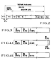
- Fig. 2 shows a frame configuration used in this system.
- one downward frame has a 4-ms (2,816-bit) configuration, and consists of a guard time GT0 (22 bits), a control time slot TS0 (304 bits), and fifteen 166-bit speech time slots TS1 to TS15.
- the control time slot TS0 has a bit configuration shown in Fig. 3, which includes a preamble PRE (16 bits), a frame synchronization FRO (16 bits), and control information C (272 bits).
- Figs. 4A and 4B show bit configurations of time slots of speech and data, respectively.
- reference symbol FRNV denotes a time slot synchronization voice start code word
- FRNC a time slot synchronization data start code word
- I speech or data information
- E & M and INS additional speech information.
- the control time slot TS0 is always transmitted. If the 15 time slots are equally assigned to the three service zones A, B, and C, each zone can use five time slots. For example, the time slots TS1 to TS5, TS6 to TS10, and TS11 to TS15 are respectively assigned to the zones A, B, and C. It should be noted that the time slots may be assigned to each zone by using so-called demand-assign technique.
- Fig. 5 shows the arrangement of the repeater station 5 in the system shown in Fig. 1.
- the output terminal of a downward receiver 10 is connected to the input terminal of a serial-to-parallel converter 11.
- the serial-to-parallel converter 11 receives serial input data and outputs parallel data for each data corresponding to each time slot.
- the converter 11 supplies the parallel data for each time slot to those of start code detectors 121 to 12 n (in this case, n is 15) and random-access memories (RAMs) 131 to 13 n which correspond with the time slot.
- the output terminals of the start code detectors 121 to 12 n are respectively connected to the first input terminals of corresponding AND gates 141 to 14 n .
- the second input terminals of the AND gates 141 to 14 n respectively receive downward squelch signals 1121 to 112 n from the receiver 10.
- the third input terminals of the AND gates 141 to 14 n respectively receive the output signals from timing circuits 251 to 25 n (to be described later).
- the output terminals of the AND gates 141 to 14 n are respectively connected to the control input terminals of the corresponding memories 131 to 13 n .
- Parallel data from memories 131 to 13 n are respectively supplied to the input terminal of parallel-to-serial converter 16.
- Downward serial transmission data 113 is supplied from the parallel-to-serial converter 16 to a downward transmitter 30.
- the output terminal of an upward receiver 20 is connected to the input terminal of a serial-to-parallel converter 21.
- the output from the serial-to-parallel converter 21 is supplied to those of start code detectors 221 to 22 n and memories 231 to 23 n corresponding to each time slot.
- the output terminals of the start code detectors 221 to 22 n are respectively connected to one input terminals of AND gates 241 to 24 n .
- the other input terminals of the AND gates 241 to 24 n respectively receive upward squelch signals 1221 to 122 n from the receiver 20.
- the output terminals of the AND gates 241 to 24 n are respectively connected to the control input terminals of the corresponding memories 231 to 23 n and the input terminals of the timing circuits 251 to 25 n .
- Parallel data from the memories 231 to 23 n are supplied to the input terminal of parallel-to-serial converter 26.
- Upward serial transmission data 123 converted is supplied from parallel-to-serial converter 26 to an upward transmitter 40.
- Reception data received and demodulated by the downward receiver 10 is input to the serial-to-parallel converter 11.
- the input data converted to parallel data by the converter 11 is input to those of the start code detectors 121 to 12 n and the memories 131 to 13 n which correspond with its time slot.
- the start code detectors 121 and 12 n produce High-level ("H") output signals.
- the receiver 10 sets to "H” level the downward squelch signals 1121 to 112 n during reception of the input signals.
- the outputs from the AND gates 141 to 14 n will not go “H” simply upon detection of the start codes of the corresponding time slots and setting of the squelch signals at "H" level.
- the outputs from the AND gates 141 to 14 n go "H” only when the "H" signals are supplied thereto from the corresponding timing circuits 251 to 25 n . Then, the data supplied from the corresponding memories 131 to 13 n is output through the parallel-to-serial converter 16 to the downward transmitter 30.
- the timing circuits 251 to 25 n produce "H" output signals as follows.
- the reception data from the downward repeater station 6 (Fig. 1) is input to the serial-to-parallel converter 21, and the outputs therefrom are respectively supplied to the start code detectors 221 to 22 n and the memories 231 to 23 n .
- the outputs from the AND gates 241 to 24 n corresponding to the respective time slots go to "H" level.
- data from the memories 231 to 23 n are transmitted from the upward transmitter 40 through the parallel-to-serial converter 26.
- the "H” outputs from the AND gates 141 to 14 n are also supplied to the corresponding timing circuits 251 to 25 n , and the "H” signals are supplied from the timing circuits 251 to 25 n to the third input terminals of the corresponding AND gates 141 to 14 n . More specifically, the repeater station 5 monitors both the upward and downward start codes, and repeates the downward data only for the time slot in which both the upward and downward start codes are detected.
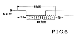
- Fig. 6 shows the operating state of the downward transmitter 30 in the higher repeater station 5 during communication of the lower repeater station 6.
- the present invention is very effective to reduce the power consumption of the higher repeater stations when a large number of repeater stations are installed.
Landscapes
- Engineering & Computer Science (AREA)
- Computer Networks & Wireless Communication (AREA)
- Signal Processing (AREA)
- Time-Division Multiplex Systems (AREA)
- Mobile Radio Communication Systems (AREA)
- Radio Relay Systems (AREA)
- Bidirectional Digital Transmission (AREA)
Claims (6)
- Zeitmultiplex-Mehrfachzugriff-Funkübertragungssystem mit:
einer Basisstation (4);
mehreren Verstärkerstationen (5, 6), um ein Funksignal aufeinanderfolgend zu verstärken, das von der Basisstation empfangen oder gesendet werden soll; und
mehreren Anschlüssen (5', 6'), um das Funksignal über die Verstärkerstationen zu der Basisstation zu übertragen,
wobei jede der Verstärkerstationen eine Verstärkereinheit aufweist, um das Funksignal unter Verwendung eines Zeitschlitzes, das jedem der Anschlüsse zugeordnet ist, zu verstärken, dadurch gekennzeichnet, daß
jede der Verstärkerstationen ferner aufweist: eine Einrichtung (22), um einen Zeitschlitz in der Aufwärtsübertragung festzustellen, und Einrichtungen (14, 25), um die Verstärkereinrichtung nur dann zu betreiben, wenn ein Zeitschlitz in der Abwärtsübertragung dem festgestellten Zeitschlitz in der Aufwärtsübertragung entspricht. - System nach Anspruch 1, wobei die Verstärkungseinrichtung aufweist: eine Speichereinrichtung (13, 23), um die Aufwärts- und Abwärtsempfangssignale zu speichern; Einrichtungen (12, 22), um einen Zeitschlitz im Betrieb festzustellen; Einrichtungen (14, 24), um eine Ausleseoperation der Speichereinrichtungen entsprechend dem festgestellten Zeitschlitz zu steuern; und Einrichtungen (16, 26, 30, 40), um den Ausgang der Speichereinrichtungen zu übertragen.
- System nach Anspruch 2, wobei die Einrichtung zur Betreibung der Verstärkereinrichtung aufweist: einen Synchronisierungsschaltkreis, um ein Steuersignal in Übereinstimmung mit dem Ausgang der Zeitschlitzfeststelleinrichtung (24) zu erzeugen und einen Zeitschlitz in der Aufwärtsübertragung festzustellen, und eine Einrichtung (14), um den Ausgang aus der Speichereinrichtung in Übereinstimmung mit dem Steuersignal freizugegeben.
- System nach Anspruch 2, wobei die Einrichtung zum Feststellen des Zeitschlitzes einen Schaltkreis (12) aufweist, um einen Anfangscode jedes Zeitschlitzes festzustellen.
- System nach Anspruch 2, wobei die Speichereinrichtung (13) einen Speicher mit wahlfreiem Zugriff aufweist, der für jeden Zeitschlitz vorgesehen ist.
- System nach Anspruch 3, wobei die Einrichtung (14) zum Freigeben des Ausgangs aus der Speichereinrichtung einen UND-Schaltkreis aufweist, der den Ausgang aus dem Synchronisierungsschaltkreis (25) als einen Eingang empfängt.
Applications Claiming Priority (2)
| Application Number | Priority Date | Filing Date | Title |
|---|---|---|---|
| JP60165470A JPS6225523A (ja) | 1985-07-25 | 1985-07-25 | 無線通信方式 |
| JP165470/85 | 1985-07-25 |
Publications (3)
| Publication Number | Publication Date |
|---|---|
| EP0210811A2 EP0210811A2 (de) | 1987-02-04 |
| EP0210811A3 EP0210811A3 (en) | 1989-05-03 |
| EP0210811B1 true EP0210811B1 (de) | 1992-01-29 |
Family
ID=15813023
Family Applications (1)
| Application Number | Title | Priority Date | Filing Date |
|---|---|---|---|
| EP86305579A Expired - Lifetime EP0210811B1 (de) | 1985-07-25 | 1986-07-21 | Zeitmultiplex-Vielfachzugriff-Funkübertragungssystem |
Country Status (6)
| Country | Link |
|---|---|
| US (1) | US4713809A (de) |
| EP (1) | EP0210811B1 (de) |
| JP (1) | JPS6225523A (de) |
| AU (1) | AU576729B2 (de) |
| CA (1) | CA1254681A (de) |
| DE (1) | DE3683702D1 (de) |
Families Citing this family (42)
| Publication number | Priority date | Publication date | Assignee | Title |
|---|---|---|---|---|
| WO1987006082A1 (en) * | 1986-03-25 | 1987-10-08 | Motorola, Inc. | Method and apparatus for controlling a tdm communication device |
| JPS6374234A (ja) * | 1986-09-17 | 1988-04-04 | Nec Corp | 多方向多重通信システム |
| US7106819B1 (en) * | 1987-11-20 | 2006-09-12 | Interdigital Technology Corporation | Plural subscriber system utilizing synchronized timeslots on a single frequency |
| US4821310A (en) * | 1987-12-22 | 1989-04-11 | Motorola, Inc. | Transmission trunked radio system with voice buffering and off-line dialing |
| GB8809602D0 (en) * | 1988-04-22 | 1988-05-25 | British Telecomm | Mobile radio systems |
| US4979188A (en) * | 1988-04-29 | 1990-12-18 | Motorola, Inc. | Spectrally efficient method for communicating an information signal |
| US5025442A (en) * | 1989-01-23 | 1991-06-18 | Motorola, Inc. | TDM/FDM communication system with pseudo-duplex capability |
| US5038342A (en) * | 1989-01-23 | 1991-08-06 | Motorola, Inc. | TDM/FDM communication system supporting both TDM and FDM-only communication units |
| US4942570A (en) * | 1989-01-23 | 1990-07-17 | Motorola, Inc. | Multiple control slot TDM/FDM communication system |
| JP2944113B2 (ja) * | 1989-11-01 | 1999-08-30 | 日本電気株式会社 | バッテリセービングシステム |
| GB2241850B (en) * | 1990-03-08 | 1994-05-25 | Marconi Co Ltd | Signal transmission system |
| US5014314A (en) * | 1990-04-27 | 1991-05-07 | Motorola, Inc. | Method for developing and transmitting usage context information in an RF communication system |
| US5216671A (en) * | 1990-12-13 | 1993-06-01 | Rca Licensing Corporation | High speed bit serial systems |
| US5265150A (en) * | 1991-01-30 | 1993-11-23 | At&T Bell Laboratories | Automatically configuring wireless PBX system |
| DE69211774T2 (de) * | 1991-04-19 | 1997-02-06 | Nippon Electric Co | Zeit-Multiplexkommunikationssystem |
| SE500620C2 (sv) * | 1992-12-11 | 1994-07-25 | Televerket | Repeteringsfunktion vid radiosystem med kort räckvidd |
| SE9300162L (sv) * | 1993-01-21 | 1994-07-22 | Televerket | Anordning vid mobila kommunikationssystem för att förlänga räckvidden mellan en eller flera mobila enheter och basstation |
| IT1266581B1 (it) * | 1993-07-30 | 1997-01-09 | Italtel Spa | Metodo per la ricetrasmissione di segnali digitali tra apparati mobili e stazioni fisse mediante dispositivi ripetitori in un sistema |
| SE502074C2 (sv) * | 1994-06-10 | 1995-08-07 | Telia Ab | Anordning vid repeterare i radiosystem med kort räckvidd |
| US6775531B1 (en) | 1994-07-21 | 2004-08-10 | Interdigital Technology Corporation | Subscriber terminal temperature regulation |
| US6243399B1 (en) | 1994-07-21 | 2001-06-05 | Interdigital Technology Corporation | Ring signal generator |
| PT1096692E (pt) * | 1994-07-21 | 2003-01-31 | Interdigital Tech Corp | Regulacao da temperatura interna num terminal de assinante |
| JP2661591B2 (ja) * | 1995-05-26 | 1997-10-08 | 日本電気株式会社 | 移動体通信システムにおける信号伝送方法 |
| JP2755241B2 (ja) * | 1995-08-25 | 1998-05-20 | 住友電気工業株式会社 | 無線中継器用発振検出装置およびこの装置が適用された無線中継器 |
| CA2158386A1 (en) * | 1995-09-15 | 1997-03-16 | Andrew Beasley | Rf repeaters for tdma mobile telephone systems |
| US5838226A (en) * | 1996-02-07 | 1998-11-17 | Lutron Electronics Co.Inc. | Communication protocol for transmission system for controlling and determining the status of electrical devices from remote locations |
| JPH09298521A (ja) * | 1996-05-08 | 1997-11-18 | Nec Eng Ltd | 無線中継制御方法及び無線通信中継制御方式 |
| US5963846A (en) * | 1997-03-31 | 1999-10-05 | Motorola, Inc. | Method and system for repeating pages |
| US6052558A (en) * | 1997-04-28 | 2000-04-18 | Motorola, Inc. | Networked repeater |
| US6032020A (en) * | 1997-07-28 | 2000-02-29 | Motorola, Inc. | Multi-repeater communication system |
| US6418461B1 (en) | 1997-10-06 | 2002-07-09 | Mci Communications Corporation | Intelligent call switching node in an intelligent distributed network architecture |
| JP2002535881A (ja) * | 1999-01-13 | 2002-10-22 | コーニンクレッカ フィリップス エレクトロニクス エヌ ヴィ | ワイヤレスローカルエリアネットワーク(lan)及びlanの動作方法 |
| US6690657B1 (en) * | 2000-02-25 | 2004-02-10 | Berkeley Concept Research Corporation | Multichannel distributed wireless repeater network |
| US7230932B2 (en) * | 2000-08-18 | 2007-06-12 | Nokia Mobile Phones Ltd. | Method and apparatus for discontinuous reception scheme and power saving mode for user equipment in packet access mode |
| US20030050098A1 (en) * | 2001-09-10 | 2003-03-13 | D'agati Laurence | Apparatus, system and method for an improved mobile station and base station |
| US7792089B2 (en) * | 2002-07-31 | 2010-09-07 | Cattron-Theimeg, Inc. | System and method for wireless remote control of locomotives |
| US7106569B2 (en) * | 2002-11-27 | 2006-09-12 | Sierra Wireless, Inc. | Adaptive current limiter for wireless modem |
| US20050075080A1 (en) * | 2003-10-03 | 2005-04-07 | Nanyang Technological University | Inter-chip and intra-chip wireless communications systems |
| JP4910574B2 (ja) * | 2006-08-31 | 2012-04-04 | 富士通株式会社 | 無線通信システム |
| EP2241025B1 (de) * | 2007-12-14 | 2016-05-04 | Telefonaktiebolaget LM Ericsson (publ) | Adaptive funk-repeater |
| US8787825B2 (en) * | 2007-12-14 | 2014-07-22 | Telefonaktiebolaget Lm Ericsson (Publ) | Method and apparatus for controlling the activation of an amplifier arrangement in a repeater device disposed in a radio communication system |
| DE102008037123A1 (de) * | 2008-08-08 | 2010-02-11 | Rohde & Schwarz Gmbh & Co. Kg | Verfahren und Funkrelais zur zeitstarren Kopplung |
Family Cites Families (6)
| Publication number | Priority date | Publication date | Assignee | Title |
|---|---|---|---|---|
| US4380816A (en) * | 1981-06-03 | 1983-04-19 | Raytheon Company | Apparatus for recycling complete cycles of a stored periodic signal |
| US4414661A (en) * | 1981-07-02 | 1983-11-08 | Trancom Ab | Apparatus for communicating with a fleet of vehicles |
| JPS5830774A (ja) * | 1981-08-17 | 1983-02-23 | Matsushita Electric Ind Co Ltd | 複写装置 |
| JPS58182928A (ja) * | 1982-04-20 | 1983-10-26 | Nec Corp | 無線中継方式 |
| DE3411014A1 (de) * | 1984-03-24 | 1985-09-26 | Standard Elektrik Lorenz Ag, 7000 Stuttgart | Nachrichtenuebertragungssystem |
| DE3423640A1 (de) * | 1984-06-27 | 1986-01-09 | Standard Elektrik Lorenz Ag, 7000 Stuttgart | Funksystem |
-
1985
- 1985-07-25 JP JP60165470A patent/JPS6225523A/ja not_active Withdrawn
-
1986
- 1986-07-21 US US06/888,587 patent/US4713809A/en not_active Expired - Lifetime
- 1986-07-21 EP EP86305579A patent/EP0210811B1/de not_active Expired - Lifetime
- 1986-07-21 DE DE8686305579T patent/DE3683702D1/de not_active Expired - Lifetime
- 1986-07-22 AU AU60405/86A patent/AU576729B2/en not_active Ceased
- 1986-07-22 CA CA000514333A patent/CA1254681A/en not_active Expired
Also Published As
| Publication number | Publication date |
|---|---|
| DE3683702D1 (de) | 1992-03-12 |
| JPS6225523A (ja) | 1987-02-03 |
| EP0210811A3 (en) | 1989-05-03 |
| EP0210811A2 (de) | 1987-02-04 |
| AU576729B2 (en) | 1988-09-01 |
| CA1254681A (en) | 1989-05-23 |
| US4713809A (en) | 1987-12-15 |
| AU6040586A (en) | 1987-01-29 |
Similar Documents
| Publication | Publication Date | Title |
|---|---|---|
| US4713809A (en) | Time division multiple access radio communications system | |
| EP0270216B1 (de) | Kommunikationssystem mit dynamischer Rahmenlänge und Stationen für ein solches System | |
| EP0030551B1 (de) | Technik zum erhöhen der regengrenze bei einem kommunikationssystem | |
| US5850593A (en) | Mobile communication for a mobile station near or outside a service area of a base station | |
| CA2059079C (en) | Automatically configuring wireless pbx system | |
| EP0582323B1 (de) | Verfahren und Vorrichtung zur Diversityübertragung und Empfang | |
| US5257019A (en) | Satellite selective call signalling system | |
| EP0275118B1 (de) | TDMA-System und Methode geschickt zur individuellen Kontrolle der elektrischen Stärke von Data-bursts | |
| KR100295734B1 (ko) | 코드 분할 다중 액세스 이동국 장치 및 코드 분할 다중 액세스송신 방법 | |
| US5586122A (en) | Time division multiple access mobile wireless telecommunication system | |
| EP0053399B1 (de) | Verfahren und System für SS-TDMA | |
| US5390165A (en) | Method and apparatus for transmitting digital data packets on a wireless channel | |
| EP0108938A1 (de) | Digitale Rufanlage mit Bit-Geschwindigkeitsumschalter und zugehöriger digitaler Empfänger | |
| MY109292A (en) | Communication methods and means in a tdma cellular mobile radio system | |
| JPS5986928A (ja) | 通信システム | |
| US9674834B2 (en) | Hybrid apparatus using physical channels | |
| US7356355B2 (en) | Wireless base station for reducing interference from a control signal emitted by another wireless base station | |
| US5210752A (en) | Radio tele-communication system using multichannel access scheme | |
| KR100671508B1 (ko) | 시그널링 방법 및 원격 통신 시스템 | |
| US6967934B1 (en) | Radio interface for a small wireless installation in the 2.4 GHZ ISM band | |
| CA2578405A1 (en) | A method of controlling initial power ramp-up in cdma systems by using short codes | |
| US4232392A (en) | Radio transmission systems | |
| JP3122267B2 (ja) | ダイバーシチ通信方式 | |
| US6459691B1 (en) | System for communication between sub-transmission units under control of main transmission unit | |
| CN114189879B (zh) | 一种智能中继器的下行波束训练指示方法及装置 |
Legal Events
| Date | Code | Title | Description |
|---|---|---|---|
| PUAI | Public reference made under article 153(3) epc to a published international application that has entered the european phase |
Free format text: ORIGINAL CODE: 0009012 |
|
| 17P | Request for examination filed |
Effective date: 19860815 |
|
| AK | Designated contracting states |
Kind code of ref document: A2 Designated state(s): DE FR GB IT NL SE |
|
| PUAL | Search report despatched |
Free format text: ORIGINAL CODE: 0009013 |
|
| AK | Designated contracting states |
Kind code of ref document: A3 Designated state(s): DE FR GB IT NL SE |
|
| 17Q | First examination report despatched |
Effective date: 19910508 |
|
| GRAA | (expected) grant |
Free format text: ORIGINAL CODE: 0009210 |
|
| AK | Designated contracting states |
Kind code of ref document: B1 Designated state(s): DE FR GB IT NL SE |
|
| REF | Corresponds to: |
Ref document number: 3683702 Country of ref document: DE Date of ref document: 19920312 |
|
| ET | Fr: translation filed | ||
| ITF | It: translation for a ep patent filed | ||
| PLBE | No opposition filed within time limit |
Free format text: ORIGINAL CODE: 0009261 |
|
| STAA | Information on the status of an ep patent application or granted ep patent |
Free format text: STATUS: NO OPPOSITION FILED WITHIN TIME LIMIT |
|
| 26N | No opposition filed | ||
| EAL | Se: european patent in force in sweden |
Ref document number: 86305579.4 |
|
| PGFP | Annual fee paid to national office [announced via postgrant information from national office to epo] |
Ref country code: SE Payment date: 19970703 Year of fee payment: 12 |
|
| PGFP | Annual fee paid to national office [announced via postgrant information from national office to epo] |
Ref country code: GB Payment date: 19970716 Year of fee payment: 12 Ref country code: FR Payment date: 19970716 Year of fee payment: 12 |
|
| PGFP | Annual fee paid to national office [announced via postgrant information from national office to epo] |
Ref country code: NL Payment date: 19970731 Year of fee payment: 12 |
|
| PGFP | Annual fee paid to national office [announced via postgrant information from national office to epo] |
Ref country code: DE Payment date: 19970930 Year of fee payment: 12 |
|
| PG25 | Lapsed in a contracting state [announced via postgrant information from national office to epo] |
Ref country code: GB Free format text: LAPSE BECAUSE OF NON-PAYMENT OF DUE FEES Effective date: 19980721 |
|
| PG25 | Lapsed in a contracting state [announced via postgrant information from national office to epo] |
Ref country code: SE Free format text: LAPSE BECAUSE OF NON-PAYMENT OF DUE FEES Effective date: 19980722 |
|
| PG25 | Lapsed in a contracting state [announced via postgrant information from national office to epo] |
Ref country code: NL Free format text: LAPSE BECAUSE OF NON-PAYMENT OF DUE FEES Effective date: 19990201 |
|
| GBPC | Gb: european patent ceased through non-payment of renewal fee |
Effective date: 19980721 |
|
| EUG | Se: european patent has lapsed |
Ref document number: 86305579.4 |
|
| PG25 | Lapsed in a contracting state [announced via postgrant information from national office to epo] |
Ref country code: FR Free format text: LAPSE BECAUSE OF NON-PAYMENT OF DUE FEES Effective date: 19990331 |
|
| NLV4 | Nl: lapsed or anulled due to non-payment of the annual fee |
Effective date: 19990201 |
|
| PG25 | Lapsed in a contracting state [announced via postgrant information from national office to epo] |
Ref country code: DE Free format text: LAPSE BECAUSE OF NON-PAYMENT OF DUE FEES Effective date: 19990501 |
|
| REG | Reference to a national code |
Ref country code: FR Ref legal event code: ST |
|
| PG25 | Lapsed in a contracting state [announced via postgrant information from national office to epo] |
Ref country code: IT Free format text: LAPSE BECAUSE OF NON-PAYMENT OF DUE FEES;WARNING: LAPSES OF ITALIAN PATENTS WITH EFFECTIVE DATE BEFORE 2007 MAY HAVE OCCURRED AT ANY TIME BEFORE 2007. THE CORRECT EFFECTIVE DATE MAY BE DIFFERENT FROM THE ONE RECORDED. Effective date: 20050721 |