EP0210713A1 - Drum magazine - Google Patents
Drum magazine Download PDFInfo
- Publication number
- EP0210713A1 EP0210713A1 EP86301861A EP86301861A EP0210713A1 EP 0210713 A1 EP0210713 A1 EP 0210713A1 EP 86301861 A EP86301861 A EP 86301861A EP 86301861 A EP86301861 A EP 86301861A EP 0210713 A1 EP0210713 A1 EP 0210713A1
- Authority
- EP
- European Patent Office
- Prior art keywords
- cartridges
- cartridge
- housing
- drum
- magazine
- Prior art date
- Legal status (The legal status is an assumption and is not a legal conclusion. Google has not performed a legal analysis and makes no representation as to the accuracy of the status listed.)
- Granted
Links
Images


Classifications
-
- F—MECHANICAL ENGINEERING; LIGHTING; HEATING; WEAPONS; BLASTING
- F41—WEAPONS
- F41A—FUNCTIONAL FEATURES OR DETAILS COMMON TO BOTH SMALLARMS AND ORDNANCE, e.g. CANNONS; MOUNTINGS FOR SMALLARMS OR ORDNANCE
- F41A9/00—Feeding or loading of ammunition; Magazines; Guiding means for the extracting of cartridges
- F41A9/61—Magazines
- F41A9/64—Magazines for unbelted ammunition
- F41A9/73—Drum magazines
-
- F—MECHANICAL ENGINEERING; LIGHTING; HEATING; WEAPONS; BLASTING
- F41—WEAPONS
- F41A—FUNCTIONAL FEATURES OR DETAILS COMMON TO BOTH SMALLARMS AND ORDNANCE, e.g. CANNONS; MOUNTINGS FOR SMALLARMS OR ORDNANCE
- F41A9/00—Feeding or loading of ammunition; Magazines; Guiding means for the extracting of cartridges
- F41A9/37—Feeding two or more kinds of ammunition to the same gun; Feeding from two sides
Definitions
- This invention relates to magazines for guns. More specifically it relates to large capacity drum magazines which feed cartridges to an automatic gun.
- Drum magazines are well known in the art. See for example, U. S. Patent No. 2,131,412 to Ostman; U. S. Patent No. 4,138,923 to Brosseau; U. S. Patent No. 4,384,508 to Sullivan; and U. S. Patent No. 4,487,103 to Atchisson.
- the principal advantage of drum magazines over the more conventional box or column magazines is their greater capacity, carrying two to four times the number of cartridges of a box magazine, with correspondingly more firepower.
- drum magazines are seldom used because they require a special gun.
- Rifles are still the predominant infantry weapon today. Modern automatic rifles have two important roles. They must fire accurate single shots, which they do very well, and then by means of a selector button, they must fire fully automatic like a machine gun. The intended purpose of this second role is to eliminate the need for a secondary automatic support weapon by making the rifle an all purpose weapon. In practice, however, the rifle makes a poor machine gun. Its most obvious flaw is its small magazine, usually thirty shots. In a situation that requires full automatic fire, each magazine is emptied so quickly that the soldier must spend more time changing magazines than firing. This "down time” limits the rifle's effect and increases the soldier's vulnerability in combat.
- a large capacity drum magazine for the rifle would overcome this problem by increasing the firepower of the rifle.
- existing drum magazine technology is not compatible with existing rifle technology.
- a gun magazine serves as both an ammunition container and as a feed device. It is, of course, an essential assembly for the gun, but unlike other assemblies within the gun, which are mechanically linked together so that their functions are coordinated, the magazine is a detachable and separate unit.
- the magazine's drive mechanism without assist from the gun, must be fast enough to keep up with the gun cycle.
- In order to provide a large capacity magazine for automatic rifles, such as the M-16 it is necessary to move the mass of cartridges the required distance in the same time as in small capacity magazines originally designed for the gun.
- a larger weight of cartridges requires a larger force to accelerate them, and the force required to move 100 cartridges in a standard magazine design used with an M-16 would place so much force on the cartridge in the feed position that it would impede or jam the weapon mechanism.
- the present invention With 100 cartridge capacity, will advance each cartridge into the feed position just as fast and with no greater binding force than for a conventional 30 cartridge magazine. Because of this and the geometry of its construction, the magazine can be used on almost any modern combat rifle without modification to the gun. It does not preclude the use of standard 30 shot magazines, so the two types can be used interchangeably.
- F irepower is not always required or desirable, but when It is, the combined limit of existing rifle and magazine technology offers no better solution than a special support weapon or a bigger army.
- the present invention offers an entirely, different solution. When needed, it triples the immediate firepower of every rifleman and reduces his vulnerability in combat.
- a single drum magazine of the present invention comprises a generally cylindrical drum with an opening for the exit of cartridges from within the drum.
- a spring driven rotor within the drum carries two concentric rings of cartridges, oriented with their axes approximately parallel to the drum axis, in a channel defined by the outer circumference of the rotor and the interior of the cylindrical drum wall.
- the rotor engages the inner concentric ring of cartridges, and the width of said channel is less than the diameter of two cartridges, such that the outer concentric ring of cartridges is necessarily offset from the cartridges in the inner ring.
- the cartridges in the puter ring are thereby nested in recesses formed between adjacent cartridges in the inner ring.
- each cartridge in the outer ring of cartridges is also forced to move by contact with a cartridge of the inner ring just behind it with respect to the direction of rotation. Also, since the outer ring of cartridges has a greater circumference than the inner ring, there will be gaps between adjacent pairs of outer ring cartridges.
- An exit channel between the rotor and the magazine exit reduces the width of the cartridge channel from that of the width of the offset double row of cartridges to that of a single row of cartridges.
- This reduction in width may be accomplished by means of a cam blade which forces cartridges from the inner ring of cartridges, as they leave the rotor, into the gaps between the cartridges of the outer ring as all of the cartridges move through the narrowing passage. It should be noted that the cartridges will roll during the transition from double column to single column and that rolling friction will thereby apply to ease the merging process.
- the cartridges are driven by the force of the spring and advanced as two rings until they meet the cam blade, which gradually forces the cartridges into a single column which moves approximately twice as fast as the velocity of the cartridges in the rotor, and the magazine will be emptied in about a single rotation of the rotor.
- a means is provided to continue to push the last cartridge out of the magazine.
- This may be accomplished by a follower arm attached to the rotor.
- the follower arm is pivotally attached to the rotor at one of its ends, and has a pushing surface at its other end, such as a dummy cartridge.
- the follower arm retracts within the inner circumference of the inner ring of cartridges when the magazine is loaded and extends outward and into the exit passage as the magazine empties. While the follower arm is optimally designed to force all cartridges out of the magazine, in practice an extension means may be necessary to feed the cartridge into the gun. In such case, an appropriate number of dummy cartridges may either be built within the magazine or loaded into the magazine to fill the additonal length of the extension means when the follower arm is fully extended.
- the magazine may be loaded by hand or machine by reversing the feeding process and introducing cartridges into the feed end of the magazine. As each cartridge is introduced, the preceding cartridges will move into the magazine and automatically expand into the two concentric offset rings of cartridges, causing the rotor to rotate against the spring force until the magazine is filled to capacity.
- Another embodiment of the present invention utilizes two of the drum magazines described above joined together at their respective exit openings by a connection means which directs the cartridges exiting from each drum into a feed box or extension located centrally between the drums.
- a connection means which directs the cartridges exiting from each drum into a feed box or extension located centrally between the drums.
- the cartridges exiting from each of the drums are directed to form the two staggered columns of cartridges in the central box.
- the drums are separated far enough from the central box to accomodate the width of the gun receiver between them when the central box is fitted within the gun.
- This embodiment forms a unit which is more compact than a single drum of the same cartridge capacity, fits the gun more favorably with more handling and ground clearance, and maintains the advantages of the invention as described below.
- the invention overcomes the difficulties inherent in the prior art by reducing the spring force necessary to move the desired mass of cartridges in the required time and by reducing the resultant force exerted by the cartridge to be fed into the gun for a given spring force. That is, since two rings of cartridges in the drum produce a single row of cartridges exiting the drum, to move a new cartridge into the loading position the total mass of cartridges need only be moved approximately half the distance that would be required in a prior art drum. This allows a reduction in the spring force by about a factor of two from what would be normally required to move the cartridges in the time necessary to meet the cycle time of the automatic gun.
- the effect of the gradual merging action from two rows to one row, and the resultant acceleration of the cartridges is to reduce the force on a cartridge exiting the drum from the force which the spring applies to the cartridges within the magazine. This effect also helps to make possible the high speed feeding of a larger volume of cartridges without adversely affecting the gun loading mechanism.
- box magazines have been designed which incorporate a reduction of a double column of cartridges to a single column.
- box magazines do not have the gap between cartridges at the start of the transition from a double row to a single row, and, therefore, tend to bind, which inhibits smooth acceleration of the cartridges.
- the simplicity of the design of the internal mechanism of the invention lends itself to less costly manufacturing since the magazine may be constructed with modern production methods and materials, such as by metal stampings or plastic molds. Such a magazine may be lightweight and disposable, and such features will be especially beneficial for military use.
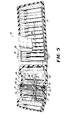
- Fig. 1 shows a double drum magazine 10 attached to an automatic rifle 11, such as an M-16.
- Fig. 2 shows the double drum magazine 10 which includes two drum portions 12 connected together by connection means 13, and a cartridge feed extension 14 attached to said connection means. It can be seen that extension 14 is of the double row type and is adapted to the shape and dimensions of at least the portion of the standard box clip which mates with the rifle.
- Fig. 3 shows in detail a double drum embodiment of the present invention.
- Each drum portion 12 of the magazine is essentially an identical mirror-image of the other.
- Each drum has a central shaft or axle 15 upon which rotate the rotors.
- the rotor comprises two wheels 16,17.
- the front wheel 16 is seen in Fig. 3.
- Each wheel has teeth 18 which provide a partial arc between each pair of teeth within which a cartridge may be seated.
- the magazine has a generally cylindrical wall 19 concentric with the circumference of the rotor wheels.
- a space 20 is provided between the rotors and the inside of the drum which forms a channel around the circumference of the rotor. This channel is optimally of a width just sufficient to hold two offset concentric rings of cartridges.
- FIG. 4 shows the magazine of Fig. 3 fully loaded with cartridges and shows the two concentric rings of cartridges within the channel space 20.
- the cartridges 21 in the inner ring of cartridges are located in the spaces between the teeth of the rotor wheels and the cartridges 22 in the outer ring are each located in a recess 23 formed between two adjacent cartridges in the inner ring.
- a cam blade 24 is provided which gradually reduces the width of the channel 20 from that of the two offset rows of cartridges at the rotors to a single row of cartridges at the exit 25 from each drum portion 12.
- the connection 26 between the two drum portions 12 directs the two single cartridge rows from each of the drum portions towards one outlet 27 which is only wide enough to allow the two rows of cartridges to pass through if they are staggered.
- An extension 28 is attached to the connection 26 which carries the two staggered rows of cartridges to a standard double lip feed throat 29.
- a follower arm 35 is attached to a pivot 36 on each rotor. As the last cartridge 37 on the rotor is cammed away from the rotor teeth by the cam blade 24, the follower arm 35 continues to transfer the force of the spring to the last cartridge to cause the cartridges to continue to move out of the magazine as cartridges are removed from the feed throat.
- the follower arm is shaped to fit within the inner ring of cartridges when the magazine if fully loaded.
- the push end of the follower arm has a dummy cartridge 38 attached thereto which occupies a space in the outer ring of cartridges.
- the follower arm 35 As the dummy cartridge 38 enters the area of the cam blade 24 when the magazine is being unloaded, it naturally moves toward the exit passage of the drum portion, which causes the follower arm 35 to swing outward and into the exit passage. As can be seen in Fig. 3, the follower arms 35 are of sufficient length to push the cartridges out of the drum, through the connection 26 and the outlet 27. However, the follower arm 35 does not extend into the extension 28, and as seen in Fig. 3, it is necessary that this space be filled with cartridges, which may be dummy cartridges. Even with such dummy cartridges 39, the number of which is dependent on the length of the extension 28, this embodiment of the magazine is capable of carrying and delivering one-hundred rounds to a weapon.
- a link 40 is provided between the dummy cartridge that is the lead cartridge when the magazine is completely unloaded and the cartridge in its row immediately behind it, to prevent the weapon from loading the dummy cartridge and to indicate that the magazine is empty.
- the magazine may be loaded by inserting cartridges into the feed throat 29. Each time a cartridge is loaded the cartridges within the extension 28 will be pushed downward toward the dividing point 41 in the connection, which naturally causes the two staggered rows to be split and directed into each of the drums. During loading the follower arm dummy cartridge 38 is naturally caused to be pushed to a position in the outer ring since the angle of the force applied to the dummy cartridge 38 causes it to rotate outward on its arc of travel. The succeeding cartridges entering the drum will naturally alternate moving into the inner ring or outer ring of cartridges due to the position of the preceding cartridge.
- cartridges will cause the rotor wheels 16 to turn against the spring force, first by the force applied to the follower arm, and after the cartridges in the inner ring begin to be located within the teeth of the rotor, by the force applied directly to the rotor.
- Cartridges may be loaded until the rotors make a complete revolution and the cartridge end of the follower arm comes into contact with the back of the cam blade 24.
- Figs. 4 and 5 it is seen that as the cartridges enter the cam area during unloading the cam blade 24 squeezes the two rings of cartridges into one row.
- the cam blade is generally centrally located between the ends of the cartridges so that each cartridge from the inner ring is cammed into the space between adjacent cartridges in the outer ring by the relatively thin cam blade 24 as a fulcrum. Since cartridges may be tapered, the thin cam blade acts as a fulcrum point contact allowing either end of the cartridge to go deeper into the path of the outer ring as room allows so that any slack at the front or rear of the single column is taken up. Furthermore, as seen in Fig. 5, the drums 12 are tilted slightly forward, as is the central box extension 28, to compensate for the accumulated angles of taper of the cartridges in the cam area, connection and extension.
- Cartridges roll during the transition from double column to single column in the cam area, and, therefore, rolling friction applies, not sliding friction.
- the camming should be gradual. In this embodiment, an angle of about 15 degrees is made between the cam blade 24 and the tangential portion 42 of the inside face of the drum, which is about the maximum angle that will can smoothly. Also, for smooth camming, it is important for the camming process to begin before the gap 43 between two adjacent cartridges in the outer ring begins to close, which will occur when each cartridge in the outer ring reaches the tangential drum portion 42. In the embodiment shown in Fig.
- the angle 44 formed between adjacent cartridges in either the inner or outer ring is 15 degrees, and therefore the angle 45 between a cartridge in the inner ring and a cartridge in the outer ring is 7 1/2 degrees. Therefore, the can blade should begin camming a cartridge in the inner ring at least 7 1/2 degrees before the beginning of the tangential portion 42 of the drum.
- the angle between the cam ⁇ blade 24 and the tangential portion 42 of the drum may be chosen as being about equal to the angle 44 formed between adjacent cartridges in the inner ring.
- teeth 18 of the rotors 16, 17 do not extend so far that they will impede an inner ring cartridge from moving forward in the cam area as necessarily caused by the camming of cartridges behind it.
- F ig. 5 also shows in greater detail the front wheel 16 and rear wheel 17 of the rotor on their axle 15.
- the spring 30 is seen to be two inverse coiled spring portions 46, 47, which may be formed with a single wire with the center of the spring anchored to the cam blade.
- Fig. 6 is an exploded drawing of the elements inside the drum, showing the parts in greater detail.
- the part numbers are the same as previously used, with a cut away portion of the front face 48 and rear face 49 of the drum shown through which the screws 50 and washers 51 attach to the axle 15.
- Spacers 52 are provided to support the spring 30 and reduce the friction of rotation of the wheels 16, 17.
- the cam blade 24 is mounted around the axel and is anchored to the drum by means of a screw 53.
- the follower arm 35 is seen to have a U-shape with cylindrical extensions 54 which fit into the pivot holes 36 of the front and rear wheels.
- the follower arm dummy cartridge comprises an appropriately shaped head 55 and tail 56 portion attached to a pin 57 through a hole 58 through the push end of the follower arm.
- the hole 58 is slightly larger than the pin and tapered outward at both openings to allow the dummy cartridge to rotate and tilt as it moves through the cam area.
- Fig. 7 is a perspective view which more clearly shows the interaction of the follower arm 35 and the cam blade 24. A portion of the push end of the follower arm is cut away 59 where the follower arm will come into contact with the cam blade when the drum is fully loaded, to provide room for an additional cartridge to be loaded into the magazine.
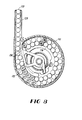
- FIG. hows a single drum embodiment 112 of the present invention.
- the parts and operation of this embodiment are essentially the same as described above, with a rotor 116 on an axle 115 moving an inner ring of cartridges 121 and an outer ring of cartridges 122 around the drum 112 and directing the cartridges 121 and 122 into a single row by means of the cam blade 124 as the lead cartridges 133 are removed.
- a follower arm 135 is utilized to push out the last cartridge as described for the double drum configuration. However, no connection (such as 26) is required and the extension 128 carries a single row of cartridges.
- the magazine of the present invention may be made of any suitable materials, such as metals and plastics.
- the drums and connections will be formed as a one piece plastic in a molding process, with as many other parts as appropriate made of plastic, to produce the lightest possible product consistent with durability and reliable operation.
- Any implementation of the invention should be appropriately sized based on the dimensions of the cartridges to be stored therein.
Abstract
Description
- This invention relates to magazines for guns. More specifically it relates to large capacity drum magazines which feed cartridges to an automatic gun.
- Drum magazines are well known in the art. See for example, U. S. Patent No. 2,131,412 to Ostman; U. S. Patent No. 4,138,923 to Brosseau; U. S. Patent No. 4,384,508 to Sullivan; and U. S. Patent No. 4,487,103 to Atchisson. The principal advantage of drum magazines over the more conventional box or column magazines is their greater capacity, carrying two to four times the number of cartridges of a box magazine, with correspondingly more firepower. However, such drum magazines are seldom used because they require a special gun.
- Rifles are still the predominant infantry weapon today. Modern automatic rifles have two important roles. They must fire accurate single shots, which they do very well, and then by means of a selector button, they must fire fully automatic like a machine gun. The intended purpose of this second role is to eliminate the need for a secondary automatic support weapon by making the rifle an all purpose weapon. In practice, however, the rifle makes a poor machine gun. Its most obvious flaw is its small magazine, usually thirty shots. In a situation that requires full automatic fire, each magazine is emptied so quickly that the soldier must spend more time changing magazines than firing. This "down time" limits the rifle's effect and increases the soldier's vulnerability in combat.
- A large capacity drum magazine for the rifle would overcome this problem by increasing the firepower of the rifle. However, existing drum magazine technology is not compatible with existing rifle technology. A gun magazine serves as both an ammunition container and as a feed device. It is, of course, an essential assembly for the gun, but unlike other assemblies within the gun, which are mechanically linked together so that their functions are coordinated, the magazine is a detachable and separate unit. The magazine's drive mechanism, without assist from the gun, must be fast enough to keep up with the gun cycle. In order to provide a large capacity magazine for automatic rifles, such as the M-16, it is necessary to move the mass of cartridges the required distance in the same time as in small capacity magazines originally designed for the gun. However, a larger weight of cartridges requires a larger force to accelerate them, and the force required to move 100 cartridges in a standard magazine design used with an M-16 would place so much force on the cartridge in the feed position that it would impede or jam the weapon mechanism.
- Unlike other drum magazines, the present invention, with 100 cartridge capacity, will advance each cartridge into the feed position just as fast and with no greater binding force than for a conventional 30 cartridge magazine. Because of this and the geometry of its construction, the magazine can be used on almost any modern combat rifle without modification to the gun. It does not preclude the use of standard 30 shot magazines, so the two types can be used interchangeably.
- Firepower is not always required or desirable, but when It is, the combined limit of existing rifle and magazine technology offers no better solution than a special support weapon or a bigger army. The present invention offers an entirely, different solution. When needed, it triples the immediate firepower of every rifleman and reduces his vulnerability in combat.
- A single drum magazine of the present invention comprises a generally cylindrical drum with an opening for the exit of cartridges from within the drum. A spring driven rotor within the drum carries two concentric rings of cartridges, oriented with their axes approximately parallel to the drum axis, in a channel defined by the outer circumference of the rotor and the interior of the cylindrical drum wall. The rotor engages the inner concentric ring of cartridges, and the width of said channel is less than the diameter of two cartridges, such that the outer concentric ring of cartridges is necessarily offset from the cartridges in the inner ring. The cartridges in the puter ring are thereby nested in recesses formed between adjacent cartridges in the inner ring. As a result, when the rotor is caused to rotate, thereby forcing the inner ring of cartridges to nove around a circle, each cartridge in the outer ring of cartridges is also forced to move by contact with a cartridge of the inner ring just behind it with respect to the direction of rotation. Also, since the outer ring of cartridges has a greater circumference than the inner ring, there will be gaps between adjacent pairs of outer ring cartridges.
- An exit channel between the rotor and the magazine exit reduces the width of the cartridge channel from that of the width of the offset double row of cartridges to that of a single row of cartridges. This reduction in width may be accomplished by means of a cam blade which forces cartridges from the inner ring of cartridges, as they leave the rotor, into the gaps between the cartridges of the outer ring as all of the cartridges move through the narrowing passage. It should be noted that the cartridges will roll during the transition from double column to single column and that rolling friction will thereby apply to ease the merging process. Thus during feeding, the cartridges are driven by the force of the spring and advanced as two rings until they meet the cam blade, which gradually forces the cartridges into a single column which moves approximately twice as fast as the velocity of the cartridges in the rotor, and the magazine will be emptied in about a single rotation of the rotor.
- When the last cartridge leaves the rotor during feeding and enters the exit passage, a means is provided to continue to push the last cartridge out of the magazine. This may be accomplished by a follower arm attached to the rotor. Preferably the follower arm is pivotally attached to the rotor at one of its ends, and has a pushing surface at its other end, such as a dummy cartridge. The follower arm retracts within the inner circumference of the inner ring of cartridges when the magazine is loaded and extends outward and into the exit passage as the magazine empties. While the follower arm is optimally designed to force all cartridges out of the magazine, in practice an extension means may be necessary to feed the cartridge into the gun. In such case, an appropriate number of dummy cartridges may either be built within the magazine or loaded into the magazine to fill the additonal length of the extension means when the follower arm is fully extended.
- The magazine may be loaded by hand or machine by reversing the feeding process and introducing cartridges into the feed end of the magazine. As each cartridge is introduced, the preceding cartridges will move into the magazine and automatically expand into the two concentric offset rings of cartridges, causing the rotor to rotate against the spring force until the magazine is filled to capacity.
- Another embodiment of the present invention utilizes two of the drum magazines described above joined together at their respective exit openings by a connection means which directs the cartridges exiting from each drum into a feed box or extension located centrally between the drums. This is especially desirable in the case of a gun, such as an M-16, which normally utilizes a conventional double column box magazine. In this case, the cartridges exiting from each of the drums are directed to form the two staggered columns of cartridges in the central box. The drums are separated far enough from the central box to accomodate the width of the gun receiver between them when the central box is fitted within the gun. This embodiment forms a unit which is more compact than a single drum of the same cartridge capacity, fits the gun more favorably with more handling and ground clearance, and maintains the advantages of the invention as described below.
- The invention overcomes the difficulties inherent in the prior art by reducing the spring force necessary to move the desired mass of cartridges in the required time and by reducing the resultant force exerted by the cartridge to be fed into the gun for a given spring force. That is, since two rings of cartridges in the drum produce a single row of cartridges exiting the drum, to move a new cartridge into the loading position the total mass of cartridges need only be moved approximately half the distance that would be required in a prior art drum. This allows a reduction in the spring force by about a factor of two from what would be normally required to move the cartridges in the time necessary to meet the cycle time of the automatic gun. In addition, the effect of the gradual merging action from two rows to one row, and the resultant acceleration of the cartridges, is to reduce the force on a cartridge exiting the drum from the force which the spring applies to the cartridges within the magazine. This effect also helps to make possible the high speed feeding of a larger volume of cartridges without adversely affecting the gun loading mechanism.
- Some box magazines have been designed which incorporate a reduction of a double column of cartridges to a single column. However, such box magazines do not have the gap between cartridges at the start of the transition from a double row to a single row, and, therefore, tend to bind, which inhibits smooth acceleration of the cartridges.
- The simplicity of the design of the internal mechanism of the invention lends itself to less costly manufacturing since the magazine may be constructed with modern production methods and materials, such as by metal stampings or plastic molds. Such a magazine may be lightweight and disposable, and such features will be especially beneficial for military use.
- In summary, it is an object of this invention to provide a magazine that will hold a large number of ammunition rounds, which may function on any unmodified magazine gun or rifle and which, therefore, does not require a special gun for its operation.
- It is a further object of this invention to provide a magazine for an automatic gun or rifle which can feed a large number of cartridges to the weapon without retarding the weapon mechanism.
- It is a still further object of this invention to provide a large capacity magazine which is simple in design, economical in construction, lightweight and compact.
- These and other objects and advantages will appear from the following description with reference to the drawings.
- Fig. 1 is a perspective view of an automatic rifle with a double drum magazine attached thereto.
- Fig. 2 is a perspective view of a double drum magazine.
- Fig. 3 is a cross-sectional view of a double drum magazine embodiment of the present invention, fully unloaded.
- Fig. 4 is the magazine of Fig. 3 fully loaded with " cartridges.
- Fig. 5 is a section taken along the line V-V of Fig. 4.
- ) Fig. 6 is an exploded view of the internal parts of the magazine and a portion of the drum walls, some of which are in partial or complete cross-section.
- Fig. 7 is a perspective view of the internal parts of the drum.
- Fig. 8 is a cross-sectional view of a single drum magazine embodiment of the present invention.
- The preferred embodiments are now described with reference to the drawings, in which like numbers indicate like parts throughout the views.
- Fig. 1 shows a
double drum magazine 10 attached to anautomatic rifle 11, such as an M-16. Fig. 2 shows thedouble drum magazine 10 which includes twodrum portions 12 connected together by connection means 13, and acartridge feed extension 14 attached to said connection means. It can be seen thatextension 14 is of the double row type and is adapted to the shape and dimensions of at least the portion of the standard box clip which mates with the rifle. - Fig. 3 shows in detail a double drum embodiment of the present invention. Each
drum portion 12 of the magazine is essentially an identical mirror-image of the other. Each drum has a central shaft oraxle 15 upon which rotate the rotors. It will be seen below that the rotor comprises twowheels 16,17. Thefront wheel 16 is seen in Fig. 3. Each wheel hasteeth 18 which provide a partial arc between each pair of teeth within which a cartridge may be seated. The magazine has a generallycylindrical wall 19 concentric with the circumference of the rotor wheels. Aspace 20 is provided between the rotors and the inside of the drum which forms a channel around the circumference of the rotor. This channel is optimally of a width just sufficient to hold two offset concentric rings of cartridges. Fig. 4 shows the magazine of Fig. 3 fully loaded with cartridges and shows the two concentric rings of cartridges within thechannel space 20. Thecartridges 21 in the inner ring of cartridges are located in the spaces between the teeth of the rotor wheels and thecartridges 22 in the outer ring are each located in arecess 23 formed between two adjacent cartridges in the inner ring. - With further reference to both Figs. 3 and 4, it is seen that a
cam blade 24 is provided which gradually reduces the width of thechannel 20 from that of the two offset rows of cartridges at the rotors to a single row of cartridges at theexit 25 from eachdrum portion 12. Theconnection 26 between the twodrum portions 12 directs the two single cartridge rows from each of the drum portions towards oneoutlet 27 which is only wide enough to allow the two rows of cartridges to pass through if they are staggered. Anextension 28 is attached to theconnection 26 which carries the two staggered rows of cartridges to a standard doublelip feed throat 29. - The motion of the cartridges out of the magazine is caused by
coiled springs 30 located at the center of each drum portion. Each spring is tensioned between atab extension 31 of thecam blade 24 and aconnection 32 to the rotor wheels, thereby forcing the rotors to turn in the direction that will move the cartridges into the cam area and out of the drum. Thus, it can be seen that as thelead cartridge 33 is removed from thefeed throat 29 the spring force on the rotors will cause the rotors to rotate and all of the cartridges to move in the direction of the feed throat until thetop cartridge 34 from the other staggered row is stopped by the lip of the feed throat. - A
follower arm 35 is attached to apivot 36 on each rotor. As thelast cartridge 37 on the rotor is cammed away from the rotor teeth by thecam blade 24, thefollower arm 35 continues to transfer the force of the spring to the last cartridge to cause the cartridges to continue to move out of the magazine as cartridges are removed from the feed throat. The follower arm is shaped to fit within the inner ring of cartridges when the magazine if fully loaded. The push end of the follower arm has adummy cartridge 38 attached thereto which occupies a space in the outer ring of cartridges. As thedummy cartridge 38 enters the area of thecam blade 24 when the magazine is being unloaded, it naturally moves toward the exit passage of the drum portion, which causes thefollower arm 35 to swing outward and into the exit passage. As can be seen in Fig. 3, thefollower arms 35 are of sufficient length to push the cartridges out of the drum, through theconnection 26 and theoutlet 27. However, thefollower arm 35 does not extend into theextension 28, and as seen in Fig. 3, it is necessary that this space be filled with cartridges, which may be dummy cartridges. Even withsuch dummy cartridges 39, the number of which is dependent on the length of theextension 28, this embodiment of the magazine is capable of carrying and delivering one-hundred rounds to a weapon. Alink 40 is provided between the dummy cartridge that is the lead cartridge when the magazine is completely unloaded and the cartridge in its row immediately behind it, to prevent the weapon from loading the dummy cartridge and to indicate that the magazine is empty. - The magazine may be loaded by inserting cartridges into the
feed throat 29. Each time a cartridge is loaded the cartridges within theextension 28 will be pushed downward toward thedividing point 41 in the connection, which naturally causes the two staggered rows to be split and directed into each of the drums. During loading the followerarm dummy cartridge 38 is naturally caused to be pushed to a position in the outer ring since the angle of the force applied to thedummy cartridge 38 causes it to rotate outward on its arc of travel. The succeeding cartridges entering the drum will naturally alternate moving into the inner ring or outer ring of cartridges due to the position of the preceding cartridge. The loading of cartridges will cause therotor wheels 16 to turn against the spring force, first by the force applied to the follower arm, and after the cartridges in the inner ring begin to be located within the teeth of the rotor, by the force applied directly to the rotor. Cartridges may be loaded until the rotors make a complete revolution and the cartridge end of the follower arm comes into contact with the back of thecam blade 24. - With reference to Figs. 4 and 5, it is seen that as the cartridges enter the cam area during unloading the
cam blade 24 squeezes the two rings of cartridges into one row. By reference to theright cam blade 24 in Fig. 5, it is seen that the cam blade is generally centrally located between the ends of the cartridges so that each cartridge from the inner ring is cammed into the space between adjacent cartridges in the outer ring by the relativelythin cam blade 24 as a fulcrum. Since cartridges may be tapered, the thin cam blade acts as a fulcrum point contact allowing either end of the cartridge to go deeper into the path of the outer ring as room allows so that any slack at the front or rear of the single column is taken up. Furthermore, as seen in Fig. 5, thedrums 12 are tilted slightly forward, as is thecentral box extension 28, to compensate for the accumulated angles of taper of the cartridges in the cam area, connection and extension. - Cartridges roll during the transition from double column to single column in the cam area, and, therefore, rolling friction applies, not sliding friction. However, in order to have the cartridges cam smoothly the camming should be gradual. In this embodiment, an angle of about 15 degrees is made between the
cam blade 24 and thetangential portion 42 of the inside face of the drum, which is about the maximum angle that will can smoothly. Also, for smooth camming, it is important for the camming process to begin before thegap 43 between two adjacent cartridges in the outer ring begins to close, which will occur when each cartridge in the outer ring reaches thetangential drum portion 42. In the embodiment shown in Fig. 4, theangle 44 formed between adjacent cartridges in either the inner or outer ring is 15 degrees, and therefore theangle 45 between a cartridge in the inner ring and a cartridge in the outer ring is 7 1/2 degrees. Therefore, the can blade should begin camming a cartridge in the inner ring at least 7 1/2 degrees before the beginning of thetangential portion 42 of the drum. In general, the angle between the cam`blade 24 and thetangential portion 42 of the drum may be chosen as being about equal to theangle 44 formed between adjacent cartridges in the inner ring. - It is also important that the
teeth 18 of therotors 16, 17 do not extend so far that they will impede an inner ring cartridge from moving forward in the cam area as necessarily caused by the camming of cartridges behind it. - Fig. 5 also shows in greater detail the
front wheel 16 and rear wheel 17 of the rotor on theiraxle 15. Thespring 30 is seen to be two inversecoiled spring portions - Fig. 6 is an exploded drawing of the elements inside the drum, showing the parts in greater detail. The part numbers are the same as previously used, with a cut away portion of the
front face 48 andrear face 49 of the drum shown through which thescrews 50 andwashers 51 attach to theaxle 15.Spacers 52 are provided to support thespring 30 and reduce the friction of rotation of thewheels 16, 17. Thecam blade 24 is mounted around the axel and is anchored to the drum by means of ascrew 53. - The
follower arm 35 is seen to have a U-shape withcylindrical extensions 54 which fit into the pivot holes 36 of the front and rear wheels. The follower arm dummy cartridge comprises an appropriately shapedhead 55 andtail 56 portion attached to apin 57 through ahole 58 through the push end of the follower arm. Thehole 58 is slightly larger than the pin and tapered outward at both openings to allow the dummy cartridge to rotate and tilt as it moves through the cam area. - The U-shaped opening of the follower arm is necessary to allow the arm to fit around the
cam blade 24 both when fully loaded (see Fig. 4) and fully unloaded (see Fig. 3). Fig. 7 is a perspective view which more clearly shows the interaction of thefollower arm 35 and thecam blade 24. A portion of the push end of the follower arm is cut away 59 where the follower arm will come into contact with the cam blade when the drum is fully loaded, to provide room for an additional cartridge to be loaded into the magazine. - Fig. hows a single drum embodiment 112 of the present invention. The parts and operation of this embodiment are essentially the same as described above, with a
rotor 116 on an axle 115 moving an inner ring ofcartridges 121 and an outer ring ofcartridges 122 around the drum 112 and directing thecartridges cam blade 124 as thelead cartridges 133 are removed. Afollower arm 135 is utilized to push out the last cartridge as described for the double drum configuration. However, no connection (such as 26) is required and theextension 128 carries a single row of cartridges. - The magazine of the present invention may be made of any suitable materials, such as metals and plastics. Ideally, the drums and connections will be formed as a one piece plastic in a molding process, with as many other parts as appropriate made of plastic, to produce the lightest possible product consistent with durability and reliable operation. Any implementation of the invention should be appropriately sized based on the dimensions of the cartridges to be stored therein.
Claims (23)
Priority Applications (1)
| Application Number | Priority Date | Filing Date | Title |
|---|---|---|---|
| AT86301861T ATE39570T1 (en) | 1985-07-24 | 1986-03-14 | DRUM MAGAZINE. |
Applications Claiming Priority (2)
| Application Number | Priority Date | Filing Date | Title |
|---|---|---|---|
| US06/759,058 US4658700A (en) | 1985-07-24 | 1985-07-24 | Drum magazine |
| US759058 | 1985-07-24 |
Publications (2)
| Publication Number | Publication Date |
|---|---|
| EP0210713A1 true EP0210713A1 (en) | 1987-02-04 |
| EP0210713B1 EP0210713B1 (en) | 1988-12-28 |
Family
ID=25054248
Family Applications (1)
| Application Number | Title | Priority Date | Filing Date |
|---|---|---|---|
| EP86301861A Expired EP0210713B1 (en) | 1985-07-24 | 1986-03-14 | Drum magazine |
Country Status (34)
| Country | Link |
|---|---|
| US (1) | US4658700A (en) |
| EP (1) | EP0210713B1 (en) |
| JP (1) | JPS62501579A (en) |
| KR (1) | KR910003038B1 (en) |
| CN (1) | CN1005045B (en) |
| AT (1) | ATE39570T1 (en) |
| AU (1) | AU568788B2 (en) |
| BR (1) | BR8606808A (en) |
| CA (1) | CA1234006A (en) |
| CU (1) | CU21942A3 (en) |
| DD (1) | DD248646A5 (en) |
| DE (2) | DE3661577D1 (en) |
| DK (1) | DK147387A (en) |
| EG (1) | EG17729A (en) |
| ES (1) | ES2000732A6 (en) |
| FI (1) | FI91322C (en) |
| GB (1) | GB2187269B (en) |
| GR (1) | GR861928B (en) |
| HK (1) | HK83792A (en) |
| HU (1) | HUT44330A (en) |
| IE (1) | IE57249B1 (en) |
| IL (1) | IL78211A0 (en) |
| MW (1) | MW1687A1 (en) |
| MX (1) | MX162988B (en) |
| MY (1) | MY100643A (en) |
| NO (1) | NO171654C (en) |
| OA (1) | OA08578A (en) |
| PH (1) | PH22511A (en) |
| SG (1) | SG792G (en) |
| SU (1) | SU1662358A3 (en) |
| TR (1) | TR23112A (en) |
| WO (1) | WO1987000614A1 (en) |
| ZA (1) | ZA865457B (en) |
| ZW (1) | ZW13986A1 (en) |
Cited By (1)
| Publication number | Priority date | Publication date | Assignee | Title |
|---|---|---|---|---|
| WO2017080800A1 (en) | 2015-11-10 | 2017-05-18 | Cmi Defence S.A. | Device for feeding medium-calibre ammunition with a rotating plate |
Families Citing this family (42)
| Publication number | Priority date | Publication date | Assignee | Title |
|---|---|---|---|---|
| US4939979A (en) * | 1986-11-12 | 1990-07-10 | Ross Capawana | Machinegun ammunition container relationship to other applications |
| US4903575A (en) * | 1988-02-29 | 1990-02-27 | Ross Capawana | Machinegun ammunition container |
| US5600083A (en) * | 1994-11-21 | 1997-02-04 | Bentley; James K. | Magazine for pump action shotgun |
| US5456153A (en) * | 1994-11-21 | 1995-10-10 | Bentley; James K. | Magazine for pump action shotgun |
| US5905224A (en) * | 1998-06-18 | 1999-05-18 | Paul William Jordan | Pulley belt magazine |
| DE102004024302B4 (en) * | 2004-05-15 | 2008-04-10 | Kraus-Maffei Wegmann Gmbh & Co. Kg | Belt box for a mounted grenade machine weapon |
| US7441491B2 (en) * | 2005-11-14 | 2008-10-28 | Annatac Industries, Incorporated | Drum magazine for firearm |
| US7806036B2 (en) * | 2006-01-03 | 2010-10-05 | Browning | Magazine apparatuses, firearms including same, and method of introducing an ammunition cartridge into a firearm |
| US8156675B2 (en) | 2007-03-08 | 2012-04-17 | Browning | Firearm magazine |
| US7942091B2 (en) * | 2007-05-08 | 2011-05-17 | Winge Michael L | Shotgun drum magazine |
| US7762174B1 (en) * | 2007-06-01 | 2010-07-27 | General Dynamics Armament And Technical Products | Ammunition container and feed system |
| BE1018257A4 (en) * | 2007-06-05 | 2010-08-03 | Otero Y Alonso Gabriel | Camembert charger for high capacity system riotgun made for cats and all other guns. |
| US20100083818A1 (en) * | 2008-10-02 | 2010-04-08 | David Joe Harris | Firearm adapter for am180 .22 caliber cartridge drums |
| US8347774B2 (en) * | 2009-10-07 | 2013-01-08 | Kevin Wayne Rich | Magazine with cartridge gear |
| US8196327B2 (en) * | 2009-10-07 | 2012-06-12 | Kevin Wayne Rich | Modular magazine assembly |
| US8448558B2 (en) * | 2009-11-09 | 2013-05-28 | Meninas Inc. | Ammunition feed system for firearm |
| US8220377B2 (en) * | 2009-11-09 | 2012-07-17 | Meninas Inc. | Ammunition feed system for firearm |
| WO2011155971A1 (en) | 2010-05-24 | 2011-12-15 | Meninas Inc. | Ammunition feed system for firearm |
| US8485083B1 (en) * | 2011-08-03 | 2013-07-16 | Mahlon Duane Care | Single-feed magazine adapter for firearms |
| KR101220503B1 (en) * | 2012-03-13 | 2013-01-10 | 노태종 | Drum type magazine |
| KR101271650B1 (en) * | 2012-08-31 | 2013-06-11 | 노태종 | Drum type magazine |
| US8839706B1 (en) * | 2013-03-05 | 2014-09-23 | Real Action Paintball (RAPY) | Drum magazine for projectiles |
| EP3105526B1 (en) * | 2014-10-14 | 2019-08-21 | Magpul Industries Corp. | Drum magazine assembly and methods |
| USD765813S1 (en) | 2014-12-31 | 2016-09-06 | Magpul Industries Corporation | Drum magazine for a firearm |
| US9772153B1 (en) | 2016-07-01 | 2017-09-26 | Smith & Wesson Corp. | Rotary ammunition magazine and follower |
| US9927194B2 (en) | 2016-07-01 | 2018-03-27 | Smith & Wesson Corp. | Rotary ammunition magazine and follower |
| US10371475B2 (en) | 2016-09-21 | 2019-08-06 | Browning | Firearm magazine |
| CA3050472A1 (en) * | 2017-01-16 | 2018-07-19 | United Tactical Systems, Llc | High capacity projectile loader |
| KR101942183B1 (en) | 2017-05-24 | 2019-01-24 | 배교환 | A magazine assembly |
| KR101942186B1 (en) | 2017-05-31 | 2019-03-18 | 배교환 | Cylindrical magazine |
| US10082353B1 (en) * | 2017-10-09 | 2018-09-25 | Pro Mag Mfg., Inc. | Drum magazine |
| CN108088305B (en) * | 2017-12-11 | 2019-08-16 | 康郦 | Large diameter automatic gun is fast automatic to select bullet method |
| US10612871B2 (en) * | 2017-12-22 | 2020-04-07 | Michael J. Davidson | Drum ammunition magazine for rimmed cartridges |
| EP3540361A1 (en) * | 2018-01-19 | 2019-09-18 | United Tactical Systems, LLC | Air actuated magazine for projectile loader |
| US10495406B1 (en) * | 2018-08-02 | 2019-12-03 | Buzz Bee Toys (HK) Co., Limited | Magazine for a toy gun |
| US10495405B1 (en) * | 2018-08-02 | 2019-12-03 | Buzz Bee Toys (HK) Co., Limited | Magazine for a toy gun |
| EP3788315A4 (en) * | 2019-06-28 | 2021-12-29 | Magpul Industries Corp. | Slide lock-back follower assembly |
| DE102020113534B3 (en) * | 2020-05-19 | 2021-09-09 | Carl Walther Gesellschaft mit beschränkter Haftung | Magazine device for firearms with optimized use of space |
| USD1013085S1 (en) * | 2020-10-15 | 2024-01-30 | Doug Hepler | Loading device for firearms magazine |
| CN113267087B (en) * | 2021-05-13 | 2023-11-17 | 华南理工大学 | External plectrum double-feeding device based on gear mechanism transmission |
| USD984557S1 (en) * | 2022-07-14 | 2023-04-25 | Guangdong Changding Supply Chain Co. LTD. | Double-tubed gel blaster |
| USD1013088S1 (en) * | 2022-12-22 | 2024-01-30 | Doug Hepler | Air gun magazine |
Citations (6)
| Publication number | Priority date | Publication date | Assignee | Title |
|---|---|---|---|---|
| DE665087C (en) * | 1935-10-02 | 1938-09-19 | Latham Valentine Stewart Black | Ammunition magazine for handguns |
| DE726574C (en) * | 1939-03-27 | 1942-10-16 | Boehmische Waffenfabrik Ag | Cartridge magazine with a rotatable cartridge holder with compartments for taking cartridges |
| DE1453938A1 (en) * | 1964-03-24 | 1970-05-14 | Sturm Ruger & Co | Multi-loading weapon with drum magazine |
| DE1553877A1 (en) * | 1967-07-25 | 1971-08-12 | Heckler & Koch Gmbh | Drum magazine for automatic handguns |
| DE2326542A1 (en) * | 1972-06-09 | 1974-01-03 | Oerlikon Buehrle Ag | CARTRIDGE MAGAZINE FOR SELF-ACTING FIRE ARMS |
| US4127954A (en) * | 1977-04-07 | 1978-12-05 | Erich Hausmann | Extended capacity cartridge magazine structure |
Family Cites Families (6)
| Publication number | Priority date | Publication date | Assignee | Title |
|---|---|---|---|---|
| BE418563A (en) * | 1935-11-26 | |||
| GB628734A (en) * | 1945-11-15 | 1949-09-05 | Hydran Products Ltd | Improvements in or relating to magazines for rounds of ammunition |
| US4138923A (en) * | 1977-06-29 | 1979-02-13 | The United States Of America As Represented By The Secretary Of The Army | Drum cartridge - magazine |
| US4384508A (en) * | 1980-12-11 | 1983-05-24 | Chartered Industries Of Singapore Private Ltd. | Drum magazine for a gun |
| US4413546A (en) * | 1980-12-17 | 1983-11-08 | Taylor Jr William J | Drum magazine for carbines or the like |
| US4487103A (en) * | 1982-06-24 | 1984-12-11 | Atchisson Maxwell G | Drum magazine |
-
1985
- 1985-07-24 US US06/759,058 patent/US4658700A/en not_active Expired - Lifetime
-
1986
- 1986-03-14 EP EP86301861A patent/EP0210713B1/en not_active Expired
- 1986-03-14 AT AT86301861T patent/ATE39570T1/en not_active IP Right Cessation
- 1986-03-14 DE DE8686301861T patent/DE3661577D1/en not_active Expired
- 1986-03-14 DE DE198686301861T patent/DE210713T1/en active Pending
- 1986-03-17 KR KR1019870700252A patent/KR910003038B1/en not_active IP Right Cessation
- 1986-03-17 WO PCT/US1986/000515 patent/WO1987000614A1/en active IP Right Grant
- 1986-03-17 BR BR8606808A patent/BR8606808A/en not_active IP Right Cessation
- 1986-03-17 AU AU56905/86A patent/AU568788B2/en not_active Ceased
- 1986-03-17 GB GB08703955A patent/GB2187269B/en not_active Expired
- 1986-03-17 JP JP61502047A patent/JPS62501579A/en active Granted
- 1986-03-17 HU HU862444A patent/HUT44330A/en active IP Right Revival
- 1986-03-18 CA CA000504405A patent/CA1234006A/en not_active Expired
- 1986-03-21 IL IL78211A patent/IL78211A0/en not_active IP Right Cessation
- 1986-07-18 ZW ZW139/86A patent/ZW13986A1/en unknown
- 1986-07-22 ZA ZA865457A patent/ZA865457B/en unknown
- 1986-07-23 CN CN86105123.8A patent/CN1005045B/en not_active Expired
- 1986-07-23 MX MX3224A patent/MX162988B/en unknown
- 1986-07-23 ES ES8600520A patent/ES2000732A6/en not_active Expired
- 1986-07-23 GR GR861928A patent/GR861928B/en unknown
- 1986-07-23 IE IE1950/86A patent/IE57249B1/en not_active IP Right Cessation
- 1986-07-23 DD DD86292803A patent/DD248646A5/en not_active IP Right Cessation
- 1986-07-24 CU CU1986140A patent/CU21942A3/es unknown
- 1986-07-24 PH PH34061A patent/PH22511A/en unknown
- 1986-07-24 EG EG460/86A patent/EG17729A/en active
- 1986-07-24 TR TR3301286A patent/TR23112A/en unknown
-
1987
- 1987-03-09 MW MW16/87A patent/MW1687A1/en unknown
- 1987-03-12 FI FI871092A patent/FI91322C/en not_active IP Right Cessation
- 1987-03-17 OA OA59088A patent/OA08578A/en unknown
- 1987-03-23 NO NO871191A patent/NO171654C/en unknown
- 1987-03-23 DK DK147387A patent/DK147387A/en not_active Application Discontinuation
- 1987-03-23 SU SU874202237A patent/SU1662358A3/en active
- 1987-07-28 MY MYPI87001152A patent/MY100643A/en unknown
-
1992
- 1992-01-04 SG SG7/92A patent/SG792G/en unknown
- 1992-10-29 HK HK837/92A patent/HK83792A/en unknown
Patent Citations (6)
| Publication number | Priority date | Publication date | Assignee | Title |
|---|---|---|---|---|
| DE665087C (en) * | 1935-10-02 | 1938-09-19 | Latham Valentine Stewart Black | Ammunition magazine for handguns |
| DE726574C (en) * | 1939-03-27 | 1942-10-16 | Boehmische Waffenfabrik Ag | Cartridge magazine with a rotatable cartridge holder with compartments for taking cartridges |
| DE1453938A1 (en) * | 1964-03-24 | 1970-05-14 | Sturm Ruger & Co | Multi-loading weapon with drum magazine |
| DE1553877A1 (en) * | 1967-07-25 | 1971-08-12 | Heckler & Koch Gmbh | Drum magazine for automatic handguns |
| DE2326542A1 (en) * | 1972-06-09 | 1974-01-03 | Oerlikon Buehrle Ag | CARTRIDGE MAGAZINE FOR SELF-ACTING FIRE ARMS |
| US4127954A (en) * | 1977-04-07 | 1978-12-05 | Erich Hausmann | Extended capacity cartridge magazine structure |
Cited By (2)
| Publication number | Priority date | Publication date | Assignee | Title |
|---|---|---|---|---|
| WO2017080800A1 (en) | 2015-11-10 | 2017-05-18 | Cmi Defence S.A. | Device for feeding medium-calibre ammunition with a rotating plate |
| US10591233B2 (en) | 2015-11-10 | 2020-03-17 | Cmi Defence S.A. | Medium-caliber ammunition supply device with turntable |
Also Published As
Similar Documents
| Publication | Publication Date | Title |
|---|---|---|
| AU568788B2 (en) | Drum magazine | |
| US4332097A (en) | Drum magazine for automatic pistol or the like | |
| US7806036B2 (en) | Magazine apparatuses, firearms including same, and method of introducing an ammunition cartridge into a firearm | |
| US4676137A (en) | Weapon firearm with magazine | |
| US20110005114A1 (en) | Drum magazine for firearm | |
| US8117956B2 (en) | Magazine for a hand gun | |
| US4413546A (en) | Drum magazine for carbines or the like | |
| WO2012092300A2 (en) | Helical ammunition magazine | |
| US4114511A (en) | Endless conveyor mechanism | |
| US20060207418A1 (en) | Hand held multibarrel automatic weapon | |
| US5544642A (en) | Multiple projectile blow gun magazine assembly | |
| JPH02197798A (en) | Magazine for multiple loaded bullet | |
| US5408915A (en) | Shell feeder for an automatic gun | |
| US4207797A (en) | Magazine for an automatic weapon | |
| NO159464B (en) | MEASURING MECHANISM FOR WEAPON WITH HIGH SHOOTING. | |
| US5370036A (en) | Telescoped ammunition revolver gun | |
| US5054365A (en) | Propellant igniter magazine for a wedge-type breechblock | |
| US4216698A (en) | Balanced Gatling gun | |
| USH164H (en) | High capacity magazine for weapons | |
| EP0061204B1 (en) | Machine gun and feed system therefor | |
| WO1985005442A1 (en) | Multi-barrel machine gun | |
| WO1995025686A1 (en) | Firearm magazine and closed loop conveyer | |
| US5315913A (en) | Gun mechanism for rapidly firing cased telescoped ammunition | |
| US6520169B1 (en) | Weapon for centrifugal propulsion of projectiles | |
| CA1191373A (en) | Dual shell feeding apparatus, with shell accumulators, for automatic guns |
Legal Events
| Date | Code | Title | Description |
|---|---|---|---|
| PUAI | Public reference made under article 153(3) epc to a published international application that has entered the european phase |
Free format text: ORIGINAL CODE: 0009012 |
|
| AK | Designated contracting states |
Kind code of ref document: A1 Designated state(s): AT BE CH DE FR GB IT LI LU NL SE |
|
| 17P | Request for examination filed |
Effective date: 19870129 |
|
| ITCL | It: translation for ep claims filed |
Representative=s name: JACOBACCI CASETTA & PERANI S.P.A. |
|
| TCNL | Nl: translation of patent claims filed | ||
| EL | Fr: translation of claims filed | ||
| TCAT | At: translation of patent claims filed | ||
| DET | De: translation of patent claims | ||
| 17Q | First examination report despatched |
Effective date: 19871105 |
|
| GRAA | (expected) grant |
Free format text: ORIGINAL CODE: 0009210 |
|
| AK | Designated contracting states |
Kind code of ref document: B1 Designated state(s): AT BE CH DE FR IT LI LU NL SE |
|
| REF | Corresponds to: |
Ref document number: 39570 Country of ref document: AT Date of ref document: 19890115 Kind code of ref document: T |
|
| REF | Corresponds to: |
Ref document number: 3661577 Country of ref document: DE Date of ref document: 19890202 |
|
| ET | Fr: translation filed | ||
| ITF | It: translation for a ep patent filed |
Owner name: JACOBACCI & PERANI S.P.A. |
|
| PLBE | No opposition filed within time limit |
Free format text: ORIGINAL CODE: 0009261 |
|
| STAA | Information on the status of an ep patent application or granted ep patent |
Free format text: STATUS: NO OPPOSITION FILED WITHIN TIME LIMIT |
|
| 26N | No opposition filed | ||
| ITTA | It: last paid annual fee | ||
| EPTA | Lu: last paid annual fee | ||
| EAL | Se: european patent in force in sweden |
Ref document number: 86301861.0 |
|
| PGFP | Annual fee paid to national office [announced via postgrant information from national office to epo] |
Ref country code: LU Payment date: 19950901 Year of fee payment: 10 |
|
| PGFP | Annual fee paid to national office [announced via postgrant information from national office to epo] |
Ref country code: NL Payment date: 19950912 Year of fee payment: 10 Ref country code: CH Payment date: 19950912 Year of fee payment: 10 |
|
| PGFP | Annual fee paid to national office [announced via postgrant information from national office to epo] |
Ref country code: BE Payment date: 19950913 Year of fee payment: 10 Ref country code: AT Payment date: 19950913 Year of fee payment: 10 |
|
| PGFP | Annual fee paid to national office [announced via postgrant information from national office to epo] |
Ref country code: SE Payment date: 19950918 Year of fee payment: 10 |
|
| PGFP | Annual fee paid to national office [announced via postgrant information from national office to epo] |
Ref country code: FR Payment date: 19950928 Year of fee payment: 10 |
|
| PGFP | Annual fee paid to national office [announced via postgrant information from national office to epo] |
Ref country code: DE Payment date: 19950929 Year of fee payment: 10 |
|
| PG25 | Lapsed in a contracting state [announced via postgrant information from national office to epo] |
Ref country code: LU Free format text: LAPSE BECAUSE OF NON-PAYMENT OF DUE FEES Effective date: 19960314 Ref country code: AT Effective date: 19960314 |
|
| PG25 | Lapsed in a contracting state [announced via postgrant information from national office to epo] |
Ref country code: SE Effective date: 19960315 |
|
| PG25 | Lapsed in a contracting state [announced via postgrant information from national office to epo] |
Ref country code: LI Effective date: 19960331 Ref country code: CH Effective date: 19960331 Ref country code: BE Effective date: 19960331 |
|
| BERE | Be: lapsed |
Owner name: THE BETA CY Effective date: 19960331 |
|
| PG25 | Lapsed in a contracting state [announced via postgrant information from national office to epo] |
Ref country code: NL Effective date: 19961001 |
|
| REG | Reference to a national code |
Ref country code: CH Ref legal event code: PL |
|
| PG25 | Lapsed in a contracting state [announced via postgrant information from national office to epo] |
Ref country code: FR Effective date: 19961129 |
|
| NLV4 | Nl: lapsed or anulled due to non-payment of the annual fee |
Effective date: 19961001 |
|
| PG25 | Lapsed in a contracting state [announced via postgrant information from national office to epo] |
Ref country code: DE Effective date: 19961203 |
|
| EUG | Se: european patent has lapsed |
Ref document number: 86301861.0 |
|
| REG | Reference to a national code |
Ref country code: FR Ref legal event code: ST |
|
| PG25 | Lapsed in a contracting state [announced via postgrant information from national office to epo] |
Ref country code: IT Free format text: LAPSE BECAUSE OF NON-PAYMENT OF DUE FEES;WARNING: LAPSES OF ITALIAN PATENTS WITH EFFECTIVE DATE BEFORE 2007 MAY HAVE OCCURRED AT ANY TIME BEFORE 2007. THE CORRECT EFFECTIVE DATE MAY BE DIFFERENT FROM THE ONE RECORDED. Effective date: 20050314 |