EP0210464A2 - Herstellen profilierter Formen - Google Patents
Herstellen profilierter Formen Download PDFInfo
- Publication number
- EP0210464A2 EP0210464A2 EP86109097A EP86109097A EP0210464A2 EP 0210464 A2 EP0210464 A2 EP 0210464A2 EP 86109097 A EP86109097 A EP 86109097A EP 86109097 A EP86109097 A EP 86109097A EP 0210464 A2 EP0210464 A2 EP 0210464A2
- Authority
- EP
- European Patent Office
- Prior art keywords
- tools
- workpiece
- male tool
- lateral
- tool
- Prior art date
- Legal status (The legal status is an assumption and is not a legal conclusion. Google has not performed a legal analysis and makes no representation as to the accuracy of the status listed.)
- Withdrawn
Links
Images
Classifications
-
- B—PERFORMING OPERATIONS; TRANSPORTING
- B21—MECHANICAL METAL-WORKING WITHOUT ESSENTIALLY REMOVING MATERIAL; PUNCHING METAL
- B21D—WORKING OR PROCESSING OF SHEET METAL OR METAL TUBES, RODS OR PROFILES WITHOUT ESSENTIALLY REMOVING MATERIAL; PUNCHING METAL
- B21D26/00—Shaping without cutting otherwise than using rigid devices or tools or yieldable or resilient pads, i.e. applying fluid pressure or magnetic forces
- B21D26/02—Shaping without cutting otherwise than using rigid devices or tools or yieldable or resilient pads, i.e. applying fluid pressure or magnetic forces by applying fluid pressure
- B21D26/053—Shaping without cutting otherwise than using rigid devices or tools or yieldable or resilient pads, i.e. applying fluid pressure or magnetic forces by applying fluid pressure characterised by the material of the blanks
- B21D26/055—Blanks having super-plastic properties
-
- B—PERFORMING OPERATIONS; TRANSPORTING
- B21—MECHANICAL METAL-WORKING WITHOUT ESSENTIALLY REMOVING MATERIAL; PUNCHING METAL
- B21D—WORKING OR PROCESSING OF SHEET METAL OR METAL TUBES, RODS OR PROFILES WITHOUT ESSENTIALLY REMOVING MATERIAL; PUNCHING METAL
- B21D19/00—Flanging or other edge treatment, e.g. of tubes
- B21D19/08—Flanging or other edge treatment, e.g. of tubes by single or successive action of pressing tools, e.g. vice jaws
Definitions
- This invention concerns the forming of contoured shapes in sheet metal, and especially the forming of elongated saddle-section or channel-section shapes in relatively thin sheet metal.
- An objective of the present invention is to overcome these problems and to provide a forming technique that is adaptable to the accurate forming of extended saddle- or channel-section shapes having section variations along the length thereof and/or contouring in planes parallel to the long axis of the shape.
- the invention provides a method of forming a contoured shape comprising bending a sheet metal workpiece into contiguity with an elongate male tool to form a shape having a saddle- or channel-section, characterised by providing said workpiece with lateral flange portions and engaging such portions with respective lateral tools movable in synchronism adjacent to the flanks of the male tool to draw the workpiece, by its said flange portions, over the male tool and into contiguity therewith.
- the lateral tools may co-operate with means for gripping the flange portions of the workpiece to enable stretch-forming of the workpiece to be satisfactorily accomplished by the said movement of the lateral tools.
- the lateral tools move in paths spaced from the flanks of the male tool by a sufficient distance both to accommodate thickness variations in a workpiece and any lateral distortions of the tools along the lengths thereof.
- the lateral tools may move in parallel paths throughout their respective synchronized movements or they may move in paths that are at least in part convergent towards the male tool axis, this latter feature being especially applicable to the forming of contoured shapes of varying section curvature, for instance shapes having aerofoil section.
- the invention also extends to apparatus for performing the method thereof and in another aspect provides shape-forming apparatus comprising an elongate male tool and a pair of lateral tools movable in synchronism adjacent to the flanks of the male tool for engaging flange portions of a workpiece to draw the latter over the male tool and into contiguity therewith.
- the said lateral tools are carried by a common carrier movable relatively to the male tool, for instance by being fixed to one platen of a press the other platen of which carries the male tool.
- the lateral tools may be fixed to such a common carrier so as to move in parallel paths as a consequence of movement of the carrier.
- the lateral tools are articulated to such common carrier so that their individual paths of motion may be controlled both by motion of the carrier and by lateral motions applied to the tools.
- the lateral tools are articulated to a common carrier and have camming elements that co-operate with external cam means to displace the tools laterally as the carrier moves relatively to the male tool.
- the external cam means may conveniently be associated with the male tool so that the paths of the lateral tools are controlled in relation to the position of the male tool.
- the cam means and the camming elements on the lateral tools may together constitute gripper means for gripping flange portions of a workpiece during the forming thereof over the male tool by the motion of the lateral tools relatively thereto.
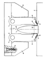
- a male tool 1 that may have a symmetrical cross-section as shown or an asymmetrical (e.g. aerofoil) cross-section and be of substantial length (for instance three metres or more) in the direction perpendicular to the plane of the paper, is supported on a bed plate 2 that may be the platen of a press or a tool support that in turn is mounted on a press platen (not shown).
- a bed plate 2 may be the platen of a press or a tool support that in turn is mounted on a press platen (not shown).
- the tool 1 may be integral with the bed plate 2, but preferably it is detachably secured to the bed plate 2 to permit exchange of tools 1 and to minimise the overall capital costs of the tool and bed plate combination for forming a particular contoured shape, and also to permit packing or shimming of the tool away from the bed plate at one or more regions along the length of the tool to obtain a required longitudinal contour of the tool 1, for instance to compensate for distortion under forming loads and/or differential thermal effects.
- the apparatus further comprises a pair of lateral tools 3, 4 that are articulated to a carrier 5, for instance by means of hinge pins or end trunnions indicated in outline at 6.
- the tools 3, 4 have a length corresponding with that of the male tool 1 in the direction perpendicular to the plane of the paper and preferably any hinge pins or trunnions 6 would be arranged only to support the tools 3 loosely in position on the carrier 5, forming thrusts acting between the tools 3, 4 and the carrier 5 during operation of the apparatus being borne by arcuate end surfaces 7 of the tools engaging correspondingly shaped surfaces of the carrier 5.
- the tools 3, 4 have restricted freedom of movement about their respective axes of articulation to the carrier 5.
- lateral outwards movement of the tools 3, 4 about such axes is restrained by abutments 8, 9 on the carrier 5 and positioned outboard of the tools 3, 4 respectively.
- the abutments 8, 9 may extend over the whole length of the carrier in the direction perpendicular to the plane of the paper, or the abutments may be localised at intervals along the length of the carrier. They may be welded or otherwise permanently secured to the carrier or they may be detachably fixed thereto, for instance by bolts such as indicated at 10.
- the free ends of the lateral tools 3, 4 are provided with forming nibs 11 shaped so as to be able to co-operate with flange portions 12 of a workpiece and with ramped surfaces 13 on the bed piate 2 adjaeent to the flanks of the tool 1.
- flange portions 12 and the immediately adjacent portions 14 of the workpiece are illustrated and the apparatus is shown with its components in approximately their respective positions at or near the end of a forming stroke of the tools 1, 3, 4.
- the carrier 5 is retracted, upwardly as seen in the drawing, away from the bed plate 2 to an extent allowing the introduction and appropriate positioning of a workpiece, that may be a flat sheet having upturned flange portions 12 but that is preferably a preform that will automatically align itself with the tool 1 when laid thereon.
- a workpiece that may be a flat sheet having upturned flange portions 12 but that is preferably a preform that will automatically align itself with the tool 1 when laid thereon.
- the carrier 5 is advanced towards the bed plate 2.
- the forming nibs 11 of the tools 3, 4 thereby engage the workpiece on each side of the tool 1 and, depending on the initial form of the workpiece, bend this about and into general conformity with the profile of the tool 1.
- the nibs 11 eventually engage the flange portions 12 of the workpiece so that further movement of the tools 3, 4 draws the workpiece down over the upper part of the tool 1.
- the abutments 8 and 9 prevent the tools 3, 4 pivoting outwardly to an extent that would allow the forming nibs 11 to disengage from the workpiece and also assure that when the tools 3, 4 approach the bed plate 2 the forming nibs 11 and the outboard regions of the flange portions 12 engaged thereby coact with the ramps 13 of the bed plate so that continued advance of the tools 3, 4 towards the latter causes the forming nibs 11 to move laterally inwards towards the base of the tool 1 while gripping the flange portions 12 between themselves and the ramps 13.
- the flange portions 12 of the workpiece are sufficiently firmly anchored to the tools 3, 4 as to allow of the generation of sufficient tension in the workpiece inboard of the forming nibs 11 to assure the forming of the workpiece into contiguity with the profile of the tool 1.
- the workpiece will be stretch-formed into exact contiguity with the profile of the tool 1 by the final motion of the lateral tools 3, 4 towards the bed plate 2.
- the carrier 5 is thereafter retracted to withdraw the tools 3, 4 clear of the formed workpiece and to allow the latter to be removed from the tool 1.
- the required workpiece section corresponds with the profile of the tool 1 above a trim line indicated at 16, and the formed workpiece, after removal from the tool 1, would be trimmed to remove its unwanted portions corresponding to those shown below the trim line 16.
- the forming operation may be carried out at ambient temperature or at elevated temperature, as desired and as required by the composition of the metal of the workpiece. For instance in the forming of titanium sheet erosion shields for helicopter rotor blades, the forming operation may be conducted at a temperature of the order of 675°C.
- the method and apparatus of the invention may of course also be applied to forming sheet metal with superplastie properties and under conditions to utilise those properties to produce a formed shape exhibiting no spring-back from the profile of the male tool.
- the method and apparatus of this invention may be utilised in conjunction with the method and apparatus disclosed in GB-A-2 139 934.
- the carrier 5 with lateral tools 3, 4 may be withdrawn and replaced by a semi-rigid diaphragm having the desired configuration for, the outer surface of the final workpiece and that is then caused to apply isostatic forming pressure to the workpiece, on the tool 1, to impart a desired final external contour to the workpiece.
- the lateral tools 3, 4 of apparatus such as illustrated in the drawing might be associated with, or be adapted to act as, a backing member for an inflatable bag member having as its internal wall a semi-rigid diaphragm of the required shape to accomplish a final pressing of the workpiece on the tool 1 after initial forming by movement of the carrier 5 towards the bed plate 2 as described.
Landscapes
- Engineering & Computer Science (AREA)
- Mechanical Engineering (AREA)
- Physics & Mathematics (AREA)
- Fluid Mechanics (AREA)
- Turning (AREA)
- Bending Of Plates, Rods, And Pipes (AREA)
- Shaping Metal By Deep-Drawing, Or The Like (AREA)
Applications Claiming Priority (2)
| Application Number | Priority Date | Filing Date | Title |
|---|---|---|---|
| GB858518567A GB8518567D0 (en) | 1985-07-23 | 1985-07-23 | Forming contoured shapes |
| GB8518567 | 1985-07-23 |
Publications (2)
| Publication Number | Publication Date |
|---|---|
| EP0210464A2 true EP0210464A2 (de) | 1987-02-04 |
| EP0210464A3 EP0210464A3 (de) | 1987-10-07 |
Family
ID=10582710
Family Applications (1)
| Application Number | Title | Priority Date | Filing Date |
|---|---|---|---|
| EP86109097A Withdrawn EP0210464A3 (de) | 1985-07-23 | 1986-07-03 | Herstellen profilierter Formen |
Country Status (3)
| Country | Link |
|---|---|
| EP (1) | EP0210464A3 (de) |
| JP (1) | JPS6254522A (de) |
| GB (1) | GB8518567D0 (de) |
Family Cites Families (4)
| Publication number | Priority date | Publication date | Assignee | Title |
|---|---|---|---|---|
| US1811259A (en) * | 1923-12-28 | 1931-06-23 | Arthur R Curtis | Method and apparatus for forming sheet metal |
| US1880454A (en) * | 1929-02-25 | 1932-10-04 | Cleveland Graphite Bronze Co | Apparatus for making bearings |
| US2339032A (en) * | 1941-06-25 | 1944-01-11 | Schlenxig Benhardt | Forming die |
| FR1036632A (fr) * | 1951-01-10 | 1953-09-09 | Sncaso | Presse à former les tôles par étirage et emboutissage simultanés |
-
1985
- 1985-07-23 GB GB858518567A patent/GB8518567D0/en active Pending
-
1986
- 1986-07-03 EP EP86109097A patent/EP0210464A3/de not_active Withdrawn
- 1986-07-22 JP JP17266486A patent/JPS6254522A/ja active Pending
Also Published As
| Publication number | Publication date |
|---|---|
| JPS6254522A (ja) | 1987-03-10 |
| EP0210464A3 (de) | 1987-10-07 |
| GB8518567D0 (en) | 1985-08-29 |
Similar Documents
| Publication | Publication Date | Title |
|---|---|---|
| US7654124B2 (en) | Method of making a sheet metal part for motor vehicles | |
| EP0475882B1 (de) | Herstellung eines Metallhohlkörpers | |
| US3988913A (en) | Isothermal metal forming apparatus | |
| EP1820578B1 (de) | Streckformverfahren für ein Blechteilsegment mit zusammengesetzten Krümmungen | |
| EP0693981B1 (de) | Vorrichtung und verfahren zur streckformung von langgestreckten metallhohlprofilen | |
| US5253502A (en) | Apparatus and method for bending and forming sheet material | |
| CA1275867C (en) | Process and device for pressforming sheet material having a small elongation | |
| JPH04223823A (ja) | 中空ブレードの形成方法 | |
| SU1440333A3 (ru) | Устройство дл изготовлени коленчатых валов | |
| US4930331A (en) | Apparatus and method for fabricating elliptical tubing | |
| US4559797A (en) | Method for forming structural parts | |
| US3978706A (en) | Precision bending work method for metallic materials | |
| CN111112467B (zh) | 一种非通径压筋板成型模具及压筋曲面板加工方法 | |
| JPH0890077A (ja) | 板材の多点成形方法及びその装置 | |
| US20090255308A1 (en) | Hydroforming Die Adjustable for Springback Correction | |
| CN214184908U (zh) | 一种带压边装置的热成型模 | |
| EP0210464A2 (de) | Herstellen profilierter Formen | |
| EP2578331B1 (de) | Verfahren und Ausrüstung zum Formen einer Gusskomponente | |
| US6675624B2 (en) | Method and device for producing a double-curved sheet-like object by means of stretch-forming | |
| CN115634964B (zh) | 一种镍合金薄板焊后矫形装置及方法 | |
| US2702578A (en) | Double acting bending dies | |
| US4821546A (en) | Two-step superplastic forming method | |
| CN210730854U (zh) | 一种锻造曲轴的工装 | |
| JPS6360006A (ja) | 圧延スタンド | |
| CN219805167U (zh) | 一种数控折弯机 |
Legal Events
| Date | Code | Title | Description |
|---|---|---|---|
| PUAI | Public reference made under article 153(3) epc to a published international application that has entered the european phase |
Free format text: ORIGINAL CODE: 0009012 |
|
| AK | Designated contracting states |
Kind code of ref document: A2 Designated state(s): AT BE CH DE FR GB IT LI LU NL SE |
|
| PUAL | Search report despatched |
Free format text: ORIGINAL CODE: 0009013 |
|
| RHK1 | Main classification (correction) |
Ipc: B21D 11/02 |
|
| AK | Designated contracting states |
Kind code of ref document: A3 Designated state(s): AT BE CH DE FR GB IT LI LU NL SE |
|
| 17P | Request for examination filed |
Effective date: 19880331 |
|
| 17Q | First examination report despatched |
Effective date: 19880624 |
|
| STAA | Information on the status of an ep patent application or granted ep patent |
Free format text: STATUS: THE APPLICATION IS DEEMED TO BE WITHDRAWN |
|
| 18D | Application deemed to be withdrawn |
Effective date: 19881105 |
|
| RIN1 | Information on inventor provided before grant (corrected) |
Inventor name: GREEN, ANTHONY |