EP0210323A2 - Failure judgment system for sensors installed in engine - Google Patents
Failure judgment system for sensors installed in engine Download PDFInfo
- Publication number
- EP0210323A2 EP0210323A2 EP86101290A EP86101290A EP0210323A2 EP 0210323 A2 EP0210323 A2 EP 0210323A2 EP 86101290 A EP86101290 A EP 86101290A EP 86101290 A EP86101290 A EP 86101290A EP 0210323 A2 EP0210323 A2 EP 0210323A2
- Authority
- EP
- European Patent Office
- Prior art keywords
- sensor
- engine
- failure
- failure judgment
- signal
- Prior art date
- Legal status (The legal status is an assumption and is not a legal conclusion. Google has not performed a legal analysis and makes no representation as to the accuracy of the status listed.)
- Granted
Links
Images


Classifications
-
- F—MECHANICAL ENGINEERING; LIGHTING; HEATING; WEAPONS; BLASTING
- F02—COMBUSTION ENGINES; HOT-GAS OR COMBUSTION-PRODUCT ENGINE PLANTS
- F02D—CONTROLLING COMBUSTION ENGINES
- F02D41/00—Electrical control of supply of combustible mixture or its constituents
- F02D41/22—Safety or indicating devices for abnormal conditions
- F02D41/222—Safety or indicating devices for abnormal conditions relating to the failure of sensors or parameter detection devices
-
- F—MECHANICAL ENGINEERING; LIGHTING; HEATING; WEAPONS; BLASTING
- F02—COMBUSTION ENGINES; HOT-GAS OR COMBUSTION-PRODUCT ENGINE PLANTS
- F02D—CONTROLLING COMBUSTION ENGINES
- F02D41/00—Electrical control of supply of combustible mixture or its constituents
- F02D41/22—Safety or indicating devices for abnormal conditions
- F02D2041/227—Limping Home, i.e. taking specific engine control measures at abnormal conditions
-
- Y—GENERAL TAGGING OF NEW TECHNOLOGICAL DEVELOPMENTS; GENERAL TAGGING OF CROSS-SECTIONAL TECHNOLOGIES SPANNING OVER SEVERAL SECTIONS OF THE IPC; TECHNICAL SUBJECTS COVERED BY FORMER USPC CROSS-REFERENCE ART COLLECTIONS [XRACs] AND DIGESTS
- Y02—TECHNOLOGIES OR APPLICATIONS FOR MITIGATION OR ADAPTATION AGAINST CLIMATE CHANGE
- Y02T—CLIMATE CHANGE MITIGATION TECHNOLOGIES RELATED TO TRANSPORTATION
- Y02T10/00—Road transport of goods or passengers
- Y02T10/10—Internal combustion engine [ICE] based vehicles
- Y02T10/40—Engine management systems
Definitions
- This invention relates to the failure judgment system for sensors which detects various data concerning engines.
- the internal combustion engine for automobiles is controlled by a microcomputer
- various data concerned with the engine is usually detected and controlled by a number of sensors.
- the failure judgment system of the sensor which detects various data for accurate control, which detects various data for accurate control, performs an important role for controlling engines and a plurality of means are adopted for the failure judgment.
- Fail safe function is a function to perform the stop of the engine or to perform the change-over control by adopting alternative standard value for emergency evacuation previously presumed for fear of the emergency such as bad condition of the engine and abnormal overheating of the catalyst probablly occurred when the control is continued reliablly in response to the signal outputted abnormally by dint of the number of the sensor.
- the above-mentioned system includes a means to judge the failure of one sensor by combining signals from the other sensors.
- the system to control the internal combustion engine for automobiles utilize the failure judgment system to detect failures of the speed sensor in accordance with the output signal of the inlet pipe pressure sensor, the engine speed sensor, and the cooling water temperature sensor, etc.
- the failure judgment is done by masking the signals from the sensor and the standard value for emergency evacuation is utilized instead of the signals, since the above-mentioned failure judgment system to detect failures of one sensor by combining the other sensors, has defect in that the judgment can not be executed even if only one of the sensors judged to be fail.
- One object of this invention is to provide the failure judgment system which enables correct judgment of sensors.
- Another object of this invention is to provide the failure judgment system which enables to make the system free from the dangerous condition.
- Further object of this invention is to provide the failure judgment system which can prevent to misjudge the sensor to be abnormal even if the sensor is normal.
- this invention is the failure judgment system of sensors installed in the engine including: sensor groups 9 and 14 being installed in an engine in order to control the engine, and providing several output signals indicating operational conditions of the engine (Pim, THW); a sensor 41 being installed in the engine so as to control the engine, providing the output signals indicating another operational condition of the engine (SPD), the sensor 41 being a target of failure judgment; failure judgment means for generating failure signal if the condition is not satisfied, and providing the standard signal indicating a standard value of each sensor, and replacing the output signal of the sensors (9 and 14) by the standard signal if the failure signal is generated in order to continue the failure judgment; fail safe means for judging if fail safe conditions in accordance with standard signals is not satisfied, inhibiting the failure judgment of the sensor 41 in order to prevent misjudgment of failure while the sensor 41 is operating normally.
- the internal combustion engine system is equipped with the electronic fuel injector where the failure judgment means for sensors of this invention is available.
- the engine system includes one cylinder of the 4- cylindered internal combustion engine and its electronic control unit.
- Numeral 1 denotes the body of the internal combustion engine.
- Numeral 2 denotes a piston.
- Numeral 3 shows a spark plug.
- Numeral 4 shows an exhaust manifold.
- Numeral 5 denotes an oxygen sensor which is installed in the exhaust manifold 4, and detects the residual oxygen concentration among the exhaust gas in analog quantity.
- Numeral 6 designates a fuel injection valve which injects fuels into the intake air in the internal combustion engine 1.
- Numeral 7 denotes an intake manifold.
- Numeral 8 shows an intake-air temperature sensor which reads the temperature of the intake air to be sent into the internal combustion engine 1.
- Numeral 9 denotes a water temperature sensor which detects the temperature of the internal combustion engine cooling water by means of the analog output change of the electric resistance.
- Numeral 10 shows a throttle valve.
- Numeral 14 shows a pressure sensor to detect the intake pressure of the surge tank 15 which absorbs the pulsation of the intake air. The intake pressure is detected by the electric signal in analog quantity.
- Numeral 16 denotes an igniter which generates the high- power voltage required to the spark plug 3.
- Numeral 17 denotes a distributor interlocking with a crankshaft which is not illustrated here.
- Numeral 18 denotes a crank angle sensor installed in the distributor 17. The sensor provides four pulse signals per one revolution of the distributor 17 or twice of the crankshaft.
- Numeral 20 shows the elctronic control unit as the electronic controlled part.
- Numeral 21 denotes a key switch.
- Numeral 22 denotes a battery which supplies electric power to the power source 23 within the electronic controlled unit 20 via the key switch 21.
- Numeral 30 designates the Central Processing Unit (CPU) to enter and calculate the data outputted from each sensor according to the control program and execute the required processes for operation and control of each unit.
- Numeral 31 designates Read Only Memory (ROM) which stores the control programs and the initial data.
- Numeral 32 denotes the Random Access Memory (RAM) where the data to be entered into the electronic control unit 20 and the data required to the operational control are temporarily read and written out.
- Numeral 33 denotes the input port to enter signals sent from each sensor.
- Numeral 34 designates the output port which drives the igniter 16 and the fuel injection valve 6 installed in each cylinder.
- Numeral 35 denotes the common bus which joins each element one another.
- the input port 33 includes the analog input part and the pulse input part while they are not illustrated.
- the analog input part the analg signals from the oxygen sensor 5, the intake-air temperature sensor 8 and the water temperature sensor 9, the pressure sensor 14 is received and converted into a binary number representative of the analog signal.
- pulse signals sent from the revolution speed sensor 41 is entered into the unit.
- the sensor 41 detects the crank angle and the vehicle speed SPD by utilizing the lead switch to detect the revolution speed of a magnet which is rotating with the shaft of the transmission gear 40.
- the above-mentioned voltage VTHW at both ends of the water temperature sensor 9 and the voltage VPim at both ends of the pressure sensor 14 are the value of voltage drop against the electric current applied from the input port 33.
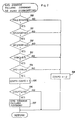
- Fig. 2 is a flowchart illustrative of the SPD sensor failure judgment 50 msec subroutine which detcts the failure of SPD sensor 41 per 50 ms.
- the SPD sensor detects the vehicle speed by utilizing the characteristic part of this embodiment.
- decision point 100 the judgment is carried out in decision point 100 to decide whether or not the intake pressure Pim given by the intake pressure Pim process routine (cf. Fig. 3) is greater than or equal to 351 mmHg. If the result of this judgment is corresponding to the range, proceed to step 101. If not, proceed to step 108.
- the object of decision point 102 is to judge whether or not the engine speed (NE) is' less than or equal to 5,000 rpm. If the result is corresponding to the range, proceed to decision point 103. If not, proceed to step 108.
- the object of decision point 102 is to judge whether or not the cooling water temperature THW decided by the internal combustion engine cooling water THW process routine (cf. Fig. 3) is greater than or equal to 81°C. If the result of this judgment is corresponding to the above-mentioned range, proceed to decision point 104. If not, proceed to step 108.
- the object of decision point 104 is to judge whether or not the vehicle speed SPD is Okm/h. If the SPD is 0 km/h, proceed to step 105. If not, proceed to step 108.
- the object of points 100 thru 103 is to judge whether or not the condition is prepared for the judgment of the vehicle speed in the point 104.
- the judgment to decide whether or not the SPD is 0 km/h can not be done until all conditions are satisfied as follows; intake pressure Pim is greater than or equal to 351 mmHg, engine speed NE is within the range of 2,400 rpm thru 5,000 rpm, cooling water temperature THW is greater than or equal to 81°C.
- step 105 the failure judgment of the SPD sensor 41 is performed in step 105, point 106 and step 107.
- step 105 the speed counter CDSPD is incremented.
- decision point 106 after the increment is completed, the value of CDSPD is judged whether or not it is greater than or equal to 160. If the result of this judgment is corresponding to the above-mentioned range', proceed to step 107 wherein the vehicle speed (SPD) sensor is judged as failure. If not, once the process step exits without judging the failure of SPD sensor.
- SPD vehicle speed
- the aforementioned points 105 thru 107 are performed only if judgment conditions of points 100 thru 104 are all satisfied. If the SPD sensor failure judgment 50 msec subroutine enters into step 105 over 160 times, the SPD sensor is judged to be failure. If less than 160 times, the SPD sensor is judged to be normal.
- step 108 the value of the vehicle speed counter CDSPD is cleared to inhibit the failure judgment of SPD sensor 41 when the judgment result of any one of point 100 thru 104 is not satisfied.
- step 108 the increment processes of CDSPD in step 105 are started from the condition that the value of CDSPD is zero.
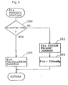
- Fig. 3 illustrates the Pim process subroutine to get the intake pressure Pim used in the point 100 of Fig. 2.
- the Pim process subroutine is initiated at decision point 200, the voltage VPim of the pressure sensor 14 is determined whether or not it is within the range from 0.5 V to 4.5 V. If the result is corresponding to the above-mentioned range, the intake pressure Pim is calculated by the value of VPim in step 201 and once the process step exits. If not corresponding to the above-mentioned range, the Pim sensor is regarded as being in failure in step 202. Then in step 203, the value of Pim is replaced with the standard value 350mmHg and once the process exits.
- Fig. 4 illustrates the THW process subroutine to get the temperature of cooling water used in point 103 of Fig. 2.
- the voltage of water temperature sensor 9 (VTHW) is judged whether or not it is within the range from 0.5 V to 4.5 V in decision point 300. If the result is corresponding to the above-mentioned range, the calculation to get the temperature of cooling water (THW) by means of the value of VTHW is carried out in step 301, and once the process exits. If the value of VTHW is not corresponding to the above-mentioned range, the THW sensor is judged as failure in step 302, the standard value 80°C is substituted for THw in step 303, and once the process exits.
- the THW is calculated when the value of VTHW is within the range from 0.5 V to 4.5 V in point 300. If not, the THW sensor is judged as failure and the THW is replaced by the standard value.
- the misjudgment of SPD sensor which is attributable to the fact that the intake pressure Pim sensor or the cooling water temperature THW sensor gets failure, can be prevented.
- the judgement is done by utilizing the value adding 1 LSB (least significant bit) to the standard value which is set up when the pressure (Pim) sensor 1% or the water temperature (THW) sensor 9 gets failure. Because of this, the number of words required for the program can be reduced in comparison with the case that the judgment whether or not the Pim sensor or the THW sensor is failure is executed. Also, storage elements, e.g, RAM 32 can be reduced.
- Fig. 5 illustrates and described the second embodiment. While the second embodiment is similar to the first embodiment in Fig. 2, there are some differences in the judgment system of the intake pressure Pim and the cooling water temperature THW in Point 100 and 103. The differences are found in only points 400 and 403 as follows:
- the function and the effect of the above-mentioned second embodiment are similar to the first embodiment. It is possible to prevent the misjudgment in the failure judgment of SPD sensor that is caused by the failure of the intake pressure Pim sensor or the cooling water temperature THW sensor. The failure of those sensors are the precondition to detect the failure of the vehicle speed (SPD) sensor 41.
- SPD vehicle speed
- the flowchart of the second embodiment decides "over standard value" without standard value, so that the process of (standard value +'1LSB] is omissible.
- Fig. 6A, Fig. 7, and Fig. 8 illustrate and describe the third embodiment.
- the third embodiment is fundamentally same as the first and the second embodiments, the following function is different.
- the pressure (Pim) sensor 14 or the water temperature (THW) sensor 9 gets failure, the failure flag PimF or THWF is set, and the failure judgment of the SPD sensor is interrupted.
- steps 505 thru 508 are omitted because they are just same as in the first and second embodiments.
- Fig. 7 is a folwchart illustrative of the PimF process subroutine, where the intake pressure Pim which is used in the flowchart of Fig. 6 is detected and the pressure sensor failure flag PimF is also set or reset. The followings are the explanation of Pim process subroutine.
- the object of the process is to judge whether or not the voltage (VPim) of pressure sensor 14 is within the range from 0.5 V to 4.5 V in decision point 600 to judge whether the sensor 14 is failure or not. If the result is corresponding to the above-mentioned range, process to step 601 and 602, where the Pim calculation process and the reset of pressure sensor failure flag PimF are carried out.
- the standard value 350 mmHg is substituted for Pim and the PimF is set.
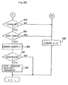
- Fig. 8 is a flowchart illustrative of the THW process subroutine, where the cooling water temperature THW to be utilized in the folwchart of Fig. 6 is detected and the water temperature sensor failure flag THW is also set or reset.
- the object of this process is to judge whether or not the voltage VTHW of water temperature sensor 9 is within the range from 0.5 V to 4.5 V in point 700 to judge whether the sensor 14 is failure or not. If the result is corresponding to the above-mentioned range, proceed to steps 701 and 702, where the Pim calculation process and the reset of water temperature sensor failure flag THWF are carried out. If the result of the judgment in point 700 is not corresponding to the above-mentioned range, the sensor 9 is judged as failure, and the subroutine proceed to steps 703 thru 705, and the THW is replaced with the standard value 80°C, and the flag THWF is set.
- the function and the effect of the above-mentioned third embodiment are similar to the first or the second embodiment. It is possible to prevent the misjudgment in the failure judgment of SPD sensor, just like the first or the second embodiment, that is caused by the failure of the intake pressure Pim sensor or the cooling water temperature THW sensor.
- the pressure sensor failure flag PimF and the water temperature sensor failure flag THWF are utilized, it is possible to provide the failure flags PimF and THWF to other controls, judgment, and indications.
- the 0 2 sensor also enables to prevent the misjudgment in failure judgment in the same manner for the SPD sensor, by utilizing the combined signals sent from other sensors.
Abstract
Description
- This invention relates to the failure judgment system for sensors which detects various data concerning engines.
- In case, the internal combustion engine for automobiles is controlled by a microcomputer, various data concerned with the engine is usually detected and controlled by a number of sensors. The failure judgment system of the sensor which detects various data for accurate control, which detects various data for accurate control, performs an important role for controlling engines and a plurality of means are adopted for the failure judgment. Fail safe function is a function to perform the stop of the engine or to perform the change-over control by adopting alternative standard value for emergency evacuation previously presumed for fear of the emergency such as bad condition of the engine and abnormal overheating of the catalyst probablly occurred when the control is continued reliablly in response to the signal outputted abnormally by dint of the number of the sensor. The above-mentioned system includes a means to judge the failure of one sensor by combining signals from the other sensors. For example, the system to control the internal combustion engine for automobiles utilize the failure judgment system to detect failures of the speed sensor in accordance with the output signal of the inlet pipe pressure sensor, the engine speed sensor, and the cooling water temperature sensor, etc. However, the failure judgment is done by masking the signals from the sensor and the standard value for emergency evacuation is utilized instead of the signals, since the above-mentioned failure judgment system to detect failures of one sensor by combining the other sensors, has defect in that the judgment can not be executed even if only one of the sensors judged to be fail.
- The system that the above-mentioned sensors judge failures by using the failure judgment condition combined, sometimes misjudge the sensor to be abnormal even if the above-mentioned condition is not actually met, since the combined judgment conditions include the standard value.
- One object of this invention is to provide the failure judgment system which enables correct judgment of sensors.
- Another object of this invention is to provide the failure judgment system which enables to make the system free from the dangerous condition.
- Further object of this invention is to provide the failure judgment system which can prevent to misjudge the sensor to be abnormal even if the sensor is normal.
- To achieve these objects, this invention is the failure judgment system of sensors installed in the engine including:
sensor groups sensor 41 being installed in the engine so as to control the engine, providing the output signals indicating another operational condition of the engine (SPD), thesensor 41 being a target of failure judgment; failure judgment means for generating failure signal if the condition is not satisfied, and providing the standard signal indicating a standard value of each sensor, and replacing the output signal of the sensors (9 and 14) by the standard signal if the failure signal is generated in order to continue the failure judgment; fail safe means for judging if fail safe conditions in accordance with standard signals is not satisfied, inhibiting the failure judgment of thesensor 41 in order to prevent misjudgment of failure while thesensor 41 is operating normally. - These and other objects of this invention may be best understood in reference to the following description of a preferred embodiment and the drawings in which:
- Fig. 1 illustrates an internal combustion engine incorporating failure judgment system of the first embodiment utilizing this invention;
- Fig. 2 illustrates a flowchart of the SPD sensor failure judgment 50 msec subroutine in the first embodiment;
- Fig. 3 is a flowchart illustrative of the Pim process subroutine in the first embodiment;
- Fig. 4 is a flowchart illustrative of the THW process subroutine in the first embodiment;
- Fig. 5 is a flowchart illustrative of the SPD sensor failure judgment 50 msec subroutine in the second embodiment;
- Fig. 6 is a folwchart illustrative of the SPD sensor failure judgment 50 msec subroutine in the third embodiment;
- Fig. 7 is a flowchart illustrative of the Pim process subroutine in the third embodiment; and
- Fig. 8 is a flowchart illustrative of the THW process subroutine in the third embodiment.
- Referring to Fig. 1, the internal combustion engine system is equipped with the electronic fuel injector where the failure judgment means for sensors of this invention is available. The engine system includes one cylinder of the 4- cylindered internal combustion engine and its electronic control unit. Numeral 1 denotes the body of the internal combustion engine.
Numeral 2 denotes a piston. Numeral 3 shows a spark plug. Numeral 4 shows an exhaust manifold. Numeral 5 denotes an oxygen sensor which is installed in theexhaust manifold 4, and detects the residual oxygen concentration among the exhaust gas in analog quantity. Numeral 6 designates a fuel injection valve which injects fuels into the intake air in theinternal combustion engine 1.Numeral 7 denotes an intake manifold. Numeral 8 shows an intake-air temperature sensor which reads the temperature of the intake air to be sent into theinternal combustion engine 1. Numeral 9 denotes a water temperature sensor which detects the temperature of the internal combustion engine cooling water by means of the analog output change of the electric resistance. Numeral 10 shows a throttle valve. Numeral 14 shows a pressure sensor to detect the intake pressure of thesurge tank 15 which absorbs the pulsation of the intake air. The intake pressure is detected by the electric signal in analog quantity. ' - Numeral 16 denotes an igniter which generates the high- power voltage required to the
spark plug 3. Numeral 17 denotes a distributor interlocking with a crankshaft which is not illustrated here. Numeral 18 denotes a crank angle sensor installed in thedistributor 17. The sensor provides four pulse signals per one revolution of thedistributor 17 or twice of the crankshaft. Numeral 20 shows the elctronic control unit as the electronic controlled part. Numeral 21 denotes a key switch. Numeral 22 denotes a battery which supplies electric power to thepower source 23 within the electronic controlledunit 20 via thekey switch 21. - The followings are the explanations of the electronic controlled
unit 20. Numeral 30 designates the Central Processing Unit (CPU) to enter and calculate the data outputted from each sensor according to the control program and execute the required processes for operation and control of each unit. Numeral 31 designates Read Only Memory (ROM) which stores the control programs and the initial data. Numeral 32 denotes the Random Access Memory (RAM) where the data to be entered into theelectronic control unit 20 and the data required to the operational control are temporarily read and written out. Numeral 33 denotes the input port to enter signals sent from each sensor. Numeral 34 designates the output port which drives theigniter 16 and thefuel injection valve 6 installed in each cylinder. Numeral 35 denotes the common bus which joins each element one another. Theinput port 33 includes the analog input part and the pulse input part while they are not illustrated. In the analog input part, the analg signals from theoxygen sensor 5, the intake-air temperature sensor 8 and thewater temperature sensor 9, thepressure sensor 14 is received and converted into a binary number representative of the analog signal. In the pulse input part, pulse signals sent from therevolution speed sensor 41 is entered into the unit. Thesensor 41 detects the crank angle and the vehicle speed SPD by utilizing the lead switch to detect the revolution speed of a magnet which is rotating with the shaft of thetransmission gear 40. The above-mentioned voltage VTHW at both ends of thewater temperature sensor 9 and the voltage VPim at both ends of thepressure sensor 14 are the value of voltage drop against the electric current applied from theinput port 33. - Next, the control system of the
electronic control unit 20 in this embodiment is described by utilizing flowcharts shown in Fig. 2 thru Fig. 4. Fig. 2 is a flowchart illustrative of the SPD sensor failure judgment 50 msec subroutine which detcts the failure ofSPD sensor 41 per 50 ms. The SPD sensor detects the vehicle speed by utilizing the characteristic part of this embodiment. - At the beginning of this flowchart, the judgment is carried out in
decision point 100 to decide whether or not the intake pressure Pim given by the intake pressure Pim process routine (cf. Fig. 3) is greater than or equal to 351 mmHg. If the result of this judgment is corresponding to the range, proceed to step 101. If not, proceed to step 108. - The object of
decision point 102 is to judge whether or not the engine speed (NE) is' less than or equal to 5,000 rpm. If the result is corresponding to the range, proceed todecision point 103. If not, proceed to step 108. - The object of
decision point 102 is to judge whether or not the cooling water temperature THW decided by the internal combustion engine cooling water THW process routine (cf. Fig. 3) is greater than or equal to 81°C. If the result of this judgment is corresponding to the above-mentioned range, proceed todecision point 104. If not, proceed to step 108. - The object of
decision point 104 is to judge whether or not the vehicle speed SPD is Okm/h. If the SPD is 0 km/h, proceed to step 105. If not, proceed to step 108. - The object of
points 100 thru 103 is to judge whether or not the condition is prepared for the judgment of the vehicle speed in thepoint 104. - That is, the judgment to decide whether or not the SPD is 0 km/h can not be done until all conditions are satisfied as follows; intake pressure Pim is greater than or equal to 351 mmHg, engine speed NE is within the range of 2,400 rpm thru 5,000 rpm, cooling water temperature THW is greater than or equal to 81°C.
- When all conditions of the above-mentioned
point 100 thru 104 are satisfied, the failure judgment of theSPD sensor 41 is performed in step 105,point 106 andstep 107. Specially in step 105 the speed counter CDSPD is incremented. Indecision point 106, after the increment is completed, the value of CDSPD is judged whether or not it is greater than or equal to 160. If the result of this judgment is corresponding to the above-mentioned range', proceed to step 107 wherein the vehicle speed (SPD) sensor is judged as failure. If not, once the process step exits without judging the failure of SPD sensor. - The aforementioned points 105 thru 107 are performed only if judgment conditions of
points 100 thru 104 are all satisfied. If the SPD sensor failure judgment 50 msec subroutine enters into step 105 over 160 times, the SPD sensor is judged to be failure. If less than 160 times, the SPD sensor is judged to be normal. - In
step 108, the value of the vehicle speed counter CDSPD is cleared to inhibit the failure judgment ofSPD sensor 41 when the judgment result of any one ofpoint 100 thru 104 is not satisfied. After thestep 108 is executed, the increment processes of CDSPD in step 105 are started from the condition that the value of CDSPD is zero. - Fig. 3 illustrates the Pim process subroutine to get the intake pressure Pim used in the
point 100 of Fig. 2. - The Pim process subroutine is initiated at
decision point 200, the voltage VPim of thepressure sensor 14 is determined whether or not it is within the range from 0.5 V to 4.5 V. If the result is corresponding to the above-mentioned range, the intake pressure Pim is calculated by the value of VPim instep 201 and once the process step exits. If not corresponding to the above-mentioned range, the Pim sensor is regarded as being in failure instep 202. Then instep 203, the value of Pim is replaced with the standard value 350mmHg and once the process exits. - Namely, if the value'of VPim in
decision point 200 is within the range from 0.5 V to 4.5 V, the value of Pim is calculated. If not, the Pim sensor is judged as failure, and the value of Pim is replaced by the standard value. - Fig. 4 illustrates the THW process subroutine to get the temperature of cooling water used in
point 103 of Fig. 2. - When the THW process subroutine is initiated, the voltage of water temperature sensor 9 (VTHW) is judged whether or not it is within the range from 0.5 V to 4.5 V in
decision point 300. If the result is corresponding to the above-mentioned range, the calculation to get the temperature of cooling water (THW) by means of the value of VTHW is carried out instep 301, and once the process exits. If the value of VTHW is not corresponding to the above-mentioned range, the THW sensor is judged as failure instep 302, the standard value 80°C is substituted for THw instep 303, and once the process exits. - In this THw process routine, therefore, the THW is calculated when the value of VTHW is within the range from 0.5 V to 4.5 V in
point 300. If not, the THW sensor is judged as failure and the THW is replaced by the standard value. - By introducing the aforementioned first embodiment, the misjudgment of SPD sensor, which is attributable to the fact that the intake pressure Pim sensor or the cooling water temperature THW sensor gets failure, can be prevented.
- In the above-mentioned
points 100 thru 103, the judgement is done by utilizing the value adding 1 LSB (least significant bit) to the standard value which is set up when the pressure (Pim)sensor 1% or the water temperature (THW)sensor 9 gets failure. Because of this, the number of words required for the program can be reduced in comparison with the case that the judgment whether or not the Pim sensor or the THW sensor is failure is executed. Also, storage elements, e.g,RAM 32 can be reduced. - Fig. 5 illustrates and described the second embodiment. While the second embodiment is similar to the first embodiment in Fig. 2, there are some differences in the judgment system of the intake pressure Pim and the cooling water temperature THW in
Point only points - Pim>= 351 mmHg (point 100)---Pim 350 mmHg (point 400) THW>=81°C (point 103)---THW 800C (point 403) Therefore, the explanations of
other points - The function and the effect of the above-mentioned second embodiment are similar to the first embodiment. It is possible to prevent the misjudgment in the failure judgment of SPD sensor that is caused by the failure of the intake pressure Pim sensor or the cooling water temperature THW sensor. The failure of those sensors are the precondition to detect the failure of the vehicle speed (SPD)
sensor 41. - In comparison with the judgment utilizing the process of (standard value + 1LSB] in
step - Fig. 6A, Fig. 7, and Fig. 8 illustrate and describe the third embodiment.
- While the third embodiment is fundamentally same as the first and the second embodiments, the following function is different. When the pressure (Pim)
sensor 14 or the water temperature (THW)sensor 9 gets failure, the failure flag PimF or THWF is set, and the failure judgment of the SPD sensor is interrupted. - Explanations of the folwchart of the third embodiment are given hereinunder. When the SPD sensor failure judgment 50 msec subroutine in Fig. 6 is started, the pressure sensor failure flag PimF or the water temperature sensor failure flag THWF is judged whether or not its value is zero in
points decision point 500. If not, proceed to step 508. After the flag judgment inpoints decision point 500 thru 504. If any one of the conditions is not satisfied, the subroutine proceed to step 508. If all of the above-mentioned conditions are satisfied, proceed to step 505. Instep 505,decision point point - If the conditions in
points step 508. - Detail explanations of
steps 505 thru 508 are omitted because they are just same as in the first and second embodiments. - Fig. 7 is a folwchart illustrative of the PimF process subroutine, where the intake pressure Pim which is used in the flowchart of Fig. 6 is detected and the pressure sensor failure flag PimF is also set or reset. The followings are the explanation of Pim process subroutine.
- The object of the process is to judge whether or not the voltage (VPim) of
pressure sensor 14 is within the range from 0.5 V to 4.5 V indecision point 600 to judge whether thesensor 14 is failure or not. If the result is corresponding to the above-mentioned range, process to step 601 and 602, where the Pim calculation process and the reset of pressure sensor failure flag PimF are carried out. - If the result of the judgment in
point 600 is not corresponding to the above-mentioned range, proceed to step 603 thru 605. After that the Pim sensor is judged as failure, the standard value 350 mmHg is substituted for Pim and the PimF is set. - Where any one of the'above-mentioned
points 600step 601 thru 605, is over, once the process exits. - Fig. 8 is a flowchart illustrative of the THW process subroutine, where the cooling water temperature THW to be utilized in the folwchart of Fig. 6 is detected and the water temperature sensor failure flag THW is also set or reset.
- The followings are the explanation of the THW process subroutine. The object of this process is to judge whether or not the voltage VTHW of
water temperature sensor 9 is within the range from 0.5 V to 4.5 V inpoint 700 to judge whether thesensor 14 is failure or not. If the result is corresponding to the above-mentioned range, proceed tosteps point 700 is not corresponding to the above-mentioned range, thesensor 9 is judged as failure, and the subroutine proceed tosteps 703 thru 705, and the THW is replaced with the standard value 80°C, and the flag THWF is set. - When any one of the above-mentioned
point 700step 701 thru 705 is over, once the process exits. - The function and the effect of the above-mentioned third embodiment are similar to the first or the second embodiment. It is possible to prevent the misjudgment in the failure judgment of SPD sensor, just like the first or the second embodiment, that is caused by the failure of the intake pressure Pim sensor or the cooling water temperature THW sensor.
- As the pressure sensor failure flag PimF and the water temperature sensor failure flag THWF are utilized, it is possible to provide the failure flags PimF and THWF to other controls, judgment, and indications.
- The 02 sensor also enables to prevent the misjudgment in failure judgment in the same manner for the SPD sensor, by utilizing the combined signals sent from other sensors.
- The foregoing description of a preferred embodiment for the purpose of illustrating the invention is not to be considered as limiting or restricting the invention, since many modifications may be made by one skilled in the art without departing from the scope of the invention.
- The embodiments of the invention in which an exclusive property or privilege is claimed are defined as follows:
Claims (6)
Applications Claiming Priority (2)
| Application Number | Priority Date | Filing Date | Title |
|---|---|---|---|
| JP60163226A JPH0711435B2 (en) | 1985-07-23 | 1985-07-23 | Method for determining sensor abnormality of internal combustion engine |
| JP163226/85 | 1985-07-23 |
Publications (3)
| Publication Number | Publication Date |
|---|---|
| EP0210323A2 true EP0210323A2 (en) | 1987-02-04 |
| EP0210323A3 EP0210323A3 (en) | 1987-10-14 |
| EP0210323B1 EP0210323B1 (en) | 1989-10-11 |
Family
ID=15769714
Family Applications (1)
| Application Number | Title | Priority Date | Filing Date |
|---|---|---|---|
| EP86101290A Expired EP0210323B1 (en) | 1985-07-23 | 1986-01-31 | Failure judgment system for sensors installed in engine |
Country Status (4)
| Country | Link |
|---|---|
| US (1) | US4780826A (en) |
| EP (1) | EP0210323B1 (en) |
| JP (1) | JPH0711435B2 (en) |
| DE (1) | DE3666265D1 (en) |
Cited By (2)
| Publication number | Priority date | Publication date | Assignee | Title |
|---|---|---|---|---|
| DE3712588A1 (en) * | 1986-04-16 | 1987-11-05 | Nippon Denso Co | DEVICE FOR DETECTING ANOMALITY OF A MOTOR VEHICLE ENGINE |
| DE3819016A1 (en) * | 1987-06-05 | 1988-12-22 | Fuji Heavy Ind Ltd | SYSTEM FOR DETECTING ABNORMAL OPERATION OF AN INTERNAL COMBUSTION ENGINE |
Families Citing this family (40)
| Publication number | Priority date | Publication date | Assignee | Title |
|---|---|---|---|---|
| JPS63131847A (en) * | 1986-04-28 | 1988-06-03 | Mitsubishi Electric Corp | Control device for car |
| JPS63246449A (en) * | 1987-03-31 | 1988-10-13 | Nippon Denso Co Ltd | Control device for internal combustion engine |
| JPH0717007Y2 (en) * | 1987-05-28 | 1995-04-19 | 日産自動車株式会社 | Vehicle speed sensor-Abnormality detection device |
| JPH01208549A (en) * | 1988-02-16 | 1989-08-22 | Fuji Heavy Ind Ltd | Device for detecting failure of intake system of engine |
| JPH01217253A (en) * | 1988-02-25 | 1989-08-30 | Nissan Motor Co Ltd | Trouble diagnosing apparatus for oxygen sensor |
| US4951632A (en) * | 1988-04-25 | 1990-08-28 | Honda Giken Kogyo K.K. | Exhaust gas component concentration sensing device and method of detecting failure thereof |
| WO1990001631A1 (en) * | 1988-07-29 | 1990-02-22 | Mitsubishi Jidosha Kogyo Kabushiki Kaisha | Fail-safe device for a temperature sensor |
| JP2749138B2 (en) * | 1988-08-08 | 1998-05-13 | 株式会社日立製作所 | Combustion abnormality detection device for internal combustion engine |
| JP2516188B2 (en) * | 1988-09-22 | 1996-07-10 | 本田技研工業株式会社 | Abnormality processing device for temperature sensor |
| DE3840148A1 (en) * | 1988-11-29 | 1990-05-31 | Bosch Gmbh Robert | METHOD AND DEVICE FOR DETECTING AN ERROR STATE OF A LAMB PROBE |
| US4875456A (en) * | 1989-02-08 | 1989-10-24 | Japan Electronic Control Systems Company Limited | Self-diagnosis system for auxiliary air control system of internal combustion engine |
| JP2663631B2 (en) * | 1989-05-23 | 1997-10-15 | 日産自動車株式会社 | Control device for automatic transmission |
| JPH0361125A (en) * | 1989-07-12 | 1991-03-15 | Robert Bosch Gmbh | Driving method for automobile |
| US5017910A (en) * | 1989-08-24 | 1991-05-21 | Deere & Company | Intermittent fault detection system |
| JPH03233160A (en) * | 1990-02-08 | 1991-10-17 | Mitsubishi Electric Corp | Control device of engine |
| US5235527A (en) * | 1990-02-09 | 1993-08-10 | Toyota Jidosha Kabushiki Kaisha | Method for diagnosing abnormality of sensor |
| DE4004086A1 (en) * | 1990-02-10 | 1991-08-14 | Bosch Gmbh Robert | SYSTEM FOR CONTROLLING OR CONTROL OF AN INTERNAL COMBUSTION ENGINE IN A MOTOR VEHICLE |
| JP2844815B2 (en) * | 1990-03-16 | 1999-01-13 | 株式会社デンソー | Vehicle electronic control unit |
| JP2503742B2 (en) * | 1990-08-04 | 1996-06-05 | 三菱電機株式会社 | Internal combustion engine fuel control system |
| US5109165A (en) * | 1990-12-11 | 1992-04-28 | Gaymar Industries, Inc. | Failsafe feedback control system |
| US5243324A (en) * | 1991-11-07 | 1993-09-07 | Ford Motor Company | Method of detecting a fault in an automotive system |
| JP2688674B2 (en) * | 1992-01-20 | 1997-12-10 | 本田技研工業株式会社 | Failure detection device and failure compensation device for fuel tank internal pressure sensor |
| JP2639287B2 (en) * | 1992-08-11 | 1997-08-06 | 株式会社デンソー | Vehicle self-diagnosis device |
| DE4423344A1 (en) * | 1994-07-04 | 1996-01-11 | Bayerische Motoren Werke Ag | Method for the detection of reversed connected lambda probes |
| US5574645A (en) * | 1995-02-28 | 1996-11-12 | Snap-On Technologies, Inc. | Manifold absolute pressure sensor emulator |
| JPH08338299A (en) * | 1995-06-10 | 1996-12-24 | Robert Bosch Gmbh | Misfire detecting method |
| JP3675108B2 (en) * | 1996-06-24 | 2005-07-27 | トヨタ自動車株式会社 | Fault diagnosis device for water temperature sensor |
| JP3189701B2 (en) * | 1996-10-03 | 2001-07-16 | 日産自動車株式会社 | Abnormality determination device for vehicle temperature sensor |
| DE19708243C1 (en) * | 1997-02-28 | 1998-08-13 | Siemens Ag | IC motor vehicle engine management method |
| JP3629982B2 (en) | 1998-10-27 | 2005-03-16 | 日産自動車株式会社 | Diagnostic device for coolant temperature sensor |
| US6434476B1 (en) * | 2000-10-04 | 2002-08-13 | Detroit Diesel Corporation | High voltage fault discrimination for EGR temperature sensor |
| DE10153396A1 (en) * | 2001-11-01 | 2003-05-28 | Siemens Ag | Device for controlling an electric fuel pump |
| DE102006021306B3 (en) * | 2006-05-08 | 2007-11-29 | Robert Bosch Gmbh | Method for diagnosis and control device for controlling a motor vehicle |
| DE102006048169A1 (en) * | 2006-10-10 | 2008-04-17 | Robert Bosch Gmbh | Method for monitoring the functionality of a controller |
| JP5218526B2 (en) * | 2010-11-11 | 2013-06-26 | トヨタ自動車株式会社 | Water temperature sensor abnormality determination device |
| JP6082242B2 (en) * | 2012-12-13 | 2017-02-15 | 日野自動車株式会社 | Water temperature sensor backup system |
| DE102014204115A1 (en) * | 2014-03-06 | 2015-09-10 | Robert Bosch Gmbh | Emergency mode for a piston engine in an aircraft |
| GB201501534D0 (en) | 2015-01-30 | 2015-03-18 | Rolls Royce Plc | Methods and systems for detecting, classifying and/or mitigating sensor error |
| JP6528869B1 (en) * | 2018-02-13 | 2019-06-12 | オムロン株式会社 | Session control apparatus, session control method and program |
| JP2021032793A (en) * | 2019-08-28 | 2021-03-01 | パイオニア株式会社 | Information processing device, control method, program, and storage medium |
Citations (5)
| Publication number | Priority date | Publication date | Assignee | Title |
|---|---|---|---|---|
| US4252098A (en) * | 1978-08-10 | 1981-02-24 | Chrysler Corporation | Air/fuel ratio control for an internal combustion engine using an exhaust gas sensor |
| US4274381A (en) * | 1978-06-26 | 1981-06-23 | Nissan Motor Company, Limited | Air/fuel ratio control system equipped with a temperature sensor fail-safe system for an internal combustion engine |
| GB2103845A (en) * | 1981-08-13 | 1983-02-23 | Honda Motor Co Ltd | Air/fuel ratio feedback control system for internal combustion engines, having atmospheric pressure - dependent fail safe function for o2 sensor |
| GB2130751A (en) * | 1982-10-01 | 1984-06-06 | Fuji Heavy Ind Ltd | Diagnostic system for an internal combustion engine |
| FR2548274A1 (en) * | 1983-06-30 | 1985-01-04 | Honda Motor Co Ltd | APPARATUS FOR DETECTING ANOMALIES OF A DEVICE FOR DETECTING OPERATING PARAMETERS OF AN INTERNAL COMBUSTION ENGINE |
Family Cites Families (9)
| Publication number | Priority date | Publication date | Assignee | Title |
|---|---|---|---|---|
| JPS566134A (en) * | 1979-06-28 | 1981-01-22 | Nissan Motor Co Ltd | Diagnostic unit of controller for car |
| JPS57169610A (en) * | 1981-04-13 | 1982-10-19 | Hitachi Ltd | Fault detector for crank angle sensor |
| JPS57203198A (en) * | 1981-06-10 | 1982-12-13 | Fuji Electric Co Ltd | Multiplexing measuring system |
| DE3213155A1 (en) * | 1982-04-08 | 1983-10-13 | VIA Gesellschaft für Verfahrenstechnik mbH, 4000 Düsseldorf | Method for the monitoring of a compressed air generating system and device for carrying out the method |
| JPS58202336A (en) * | 1982-05-20 | 1983-11-25 | Honda Motor Co Ltd | Fuel feed controlling method in time of trouble happening in temperature sensor |
| JPS59141751A (en) * | 1983-02-03 | 1984-08-14 | Nippon Soken Inc | Trouble detecting apparatus for pressure detector used in internal-combustion engine |
| DE3328450A1 (en) * | 1983-08-06 | 1985-02-28 | Daimler-Benz Ag, 7000 Stuttgart | METHOD FOR CHECKING PROBE |
| JPS60178948A (en) * | 1984-02-24 | 1985-09-12 | Honda Motor Co Ltd | Abnormality detecting and displaying device in electronic fuel supply control device for internal-combustion engine |
| JPH108831A (en) * | 1996-04-26 | 1998-01-13 | Ykk Architect Prod Kk | Constituent member for heat insulated sash |
-
1985
- 1985-07-23 JP JP60163226A patent/JPH0711435B2/en not_active Expired - Lifetime
-
1986
- 1986-01-31 DE DE8686101290T patent/DE3666265D1/en not_active Expired
- 1986-01-31 EP EP86101290A patent/EP0210323B1/en not_active Expired
- 1986-02-07 US US06/827,170 patent/US4780826A/en not_active Expired - Lifetime
Patent Citations (5)
| Publication number | Priority date | Publication date | Assignee | Title |
|---|---|---|---|---|
| US4274381A (en) * | 1978-06-26 | 1981-06-23 | Nissan Motor Company, Limited | Air/fuel ratio control system equipped with a temperature sensor fail-safe system for an internal combustion engine |
| US4252098A (en) * | 1978-08-10 | 1981-02-24 | Chrysler Corporation | Air/fuel ratio control for an internal combustion engine using an exhaust gas sensor |
| GB2103845A (en) * | 1981-08-13 | 1983-02-23 | Honda Motor Co Ltd | Air/fuel ratio feedback control system for internal combustion engines, having atmospheric pressure - dependent fail safe function for o2 sensor |
| GB2130751A (en) * | 1982-10-01 | 1984-06-06 | Fuji Heavy Ind Ltd | Diagnostic system for an internal combustion engine |
| FR2548274A1 (en) * | 1983-06-30 | 1985-01-04 | Honda Motor Co Ltd | APPARATUS FOR DETECTING ANOMALIES OF A DEVICE FOR DETECTING OPERATING PARAMETERS OF AN INTERNAL COMBUSTION ENGINE |
Cited By (2)
| Publication number | Priority date | Publication date | Assignee | Title |
|---|---|---|---|---|
| DE3712588A1 (en) * | 1986-04-16 | 1987-11-05 | Nippon Denso Co | DEVICE FOR DETECTING ANOMALITY OF A MOTOR VEHICLE ENGINE |
| DE3819016A1 (en) * | 1987-06-05 | 1988-12-22 | Fuji Heavy Ind Ltd | SYSTEM FOR DETECTING ABNORMAL OPERATION OF AN INTERNAL COMBUSTION ENGINE |
Also Published As
| Publication number | Publication date |
|---|---|
| DE3666265D1 (en) | 1989-11-16 |
| US4780826A (en) | 1988-10-25 |
| JPH0711435B2 (en) | 1995-02-08 |
| EP0210323B1 (en) | 1989-10-11 |
| EP0210323A3 (en) | 1987-10-14 |
| JPS62110120A (en) | 1987-05-21 |
Similar Documents
| Publication | Publication Date | Title |
|---|---|---|
| EP0210323A2 (en) | Failure judgment system for sensors installed in engine | |
| US6431160B1 (en) | Air-fuel ratio control apparatus for an internal combustion engine and a control method of the air-fuel ratio control apparatus | |
| US4483299A (en) | Method for detecting abnormality in sensor means for detecting a parameter relating to intake air quantity of an internal combustion engine | |
| US5454259A (en) | Failure detecting apparatus in temperature controller of air-fuel ratio sensor | |
| US7832260B2 (en) | Abnormality diagnosis apparatus for internal combustion engine | |
| US4454854A (en) | Exhaust gas recirculation control method for internal combustion engines for vehicles | |
| US4962740A (en) | Fuel controller for internal combustion engine | |
| US4510911A (en) | Method for controlling fuel supply to an internal combustion engine after termination of fuel cut | |
| USRE38051E1 (en) | Catalytic converter decontamination method | |
| EP1184548B1 (en) | Catalyst deterioration detection device for internal combustion engine | |
| EP1783362A1 (en) | Method of determining carbon fouling of internal combustion engine | |
| US8240298B2 (en) | Abnormality diagnosis apparatus for secondary air supply assembly of internal combustion engine | |
| US5606120A (en) | Misfire-detecting system for internal combustion engines | |
| US4947392A (en) | Malfunction diagnostic apparatus for vehicle control system | |
| US7280906B2 (en) | Method for detecting misfires of an internal combustion engine and device for carrying out the method | |
| US5526798A (en) | Air-fuel ratio control system for internal combustion engines | |
| JP2636565B2 (en) | Anomaly detection device | |
| KR0122459B1 (en) | Air-fuel ratio control apparatus for multi cylinder engine | |
| US6634220B1 (en) | Misfire detecting apparatus for an internal combustion engine and a method for detecting misfires | |
| US4502448A (en) | Method for controlling control systems for internal combustion engines immediately after termination of fuel cut | |
| US4748955A (en) | Apparatus for controlling internal combustion engine | |
| US5138833A (en) | Converter overtemperature protection system and method | |
| JP2002039007A (en) | Misfire control system of internal combustion engine | |
| JPH0565841A (en) | Diagnosis device for abnormality of internal combustion engine | |
| US5357789A (en) | Misfire detection system for internal combustion engine |
Legal Events
| Date | Code | Title | Description |
|---|---|---|---|
| PUAI | Public reference made under article 153(3) epc to a published international application that has entered the european phase |
Free format text: ORIGINAL CODE: 0009012 |
|
| AK | Designated contracting states |
Kind code of ref document: A2 Designated state(s): DE FR GB |
|
| PUAL | Search report despatched |
Free format text: ORIGINAL CODE: 0009013 |
|
| AK | Designated contracting states |
Kind code of ref document: A3 Designated state(s): DE FR GB |
|
| 17P | Request for examination filed |
Effective date: 19871113 |
|
| 17Q | First examination report despatched |
Effective date: 19880225 |
|
| GRAA | (expected) grant |
Free format text: ORIGINAL CODE: 0009210 |
|
| AK | Designated contracting states |
Kind code of ref document: B1 Designated state(s): DE FR GB |
|
| REF | Corresponds to: |
Ref document number: 3666265 Country of ref document: DE Date of ref document: 19891116 |
|
| ET | Fr: translation filed | ||
| PLBI | Opposition filed |
Free format text: ORIGINAL CODE: 0009260 |
|
| 26 | Opposition filed |
Opponent name: ROBERT BOSCH GMBH Effective date: 19900706 |
|
| PG25 | Lapsed in a contracting state [announced via postgrant information from national office to epo] |
Ref country code: FR Effective date: 19900928 |
|
| REG | Reference to a national code |
Ref country code: FR Ref legal event code: ST |
|
| PLBN | Opposition rejected |
Free format text: ORIGINAL CODE: 0009273 |
|
| STAA | Information on the status of an ep patent application or granted ep patent |
Free format text: STATUS: OPPOSITION REJECTED |
|
| 27O | Opposition rejected |
Effective date: 19940113 |
|
| REG | Reference to a national code |
Ref country code: GB Ref legal event code: 746 Effective date: 19960626 |
|
| REG | Reference to a national code |
Ref country code: GB Ref legal event code: IF02 |
|
| PGFP | Annual fee paid to national office [announced via postgrant information from national office to epo] |
Ref country code: GB Payment date: 20050126 Year of fee payment: 20 |
|
| PGFP | Annual fee paid to national office [announced via postgrant information from national office to epo] |
Ref country code: DE Payment date: 20050127 Year of fee payment: 20 |
|
| REG | Reference to a national code |
Ref country code: GB Ref legal event code: PE20 |
|
| APAH | Appeal reference modified |
Free format text: ORIGINAL CODE: EPIDOSCREFNO |
|
| PG25 | Lapsed in a contracting state [announced via postgrant information from national office to epo] |
Ref country code: GB Free format text: LAPSE BECAUSE OF EXPIRATION OF PROTECTION Effective date: 20060130 |