EP0210317B1 - Electric accumulator battery - Google Patents
Electric accumulator battery Download PDFInfo
- Publication number
- EP0210317B1 EP0210317B1 EP85401930A EP85401930A EP0210317B1 EP 0210317 B1 EP0210317 B1 EP 0210317B1 EP 85401930 A EP85401930 A EP 85401930A EP 85401930 A EP85401930 A EP 85401930A EP 0210317 B1 EP0210317 B1 EP 0210317B1
- Authority
- EP
- European Patent Office
- Prior art keywords
- cover
- handles
- terminals
- walls
- battery
- Prior art date
- Legal status (The legal status is an assumption and is not a legal conclusion. Google has not performed a legal analysis and makes no representation as to the accuracy of the status listed.)
- Expired - Lifetime
Links
Images

Classifications
-
- H—ELECTRICITY
- H01—ELECTRIC ELEMENTS
- H01M—PROCESSES OR MEANS, e.g. BATTERIES, FOR THE DIRECT CONVERSION OF CHEMICAL ENERGY INTO ELECTRICAL ENERGY
- H01M50/00—Constructional details or processes of manufacture of the non-active parts of electrochemical cells other than fuel cells, e.g. hybrid cells
- H01M50/20—Mountings; Secondary casings or frames; Racks, modules or packs; Suspension devices; Shock absorbers; Transport or carrying devices; Holders
- H01M50/256—Carrying devices, e.g. belts
-
- H—ELECTRICITY
- H01—ELECTRIC ELEMENTS
- H01M—PROCESSES OR MEANS, e.g. BATTERIES, FOR THE DIRECT CONVERSION OF CHEMICAL ENERGY INTO ELECTRICAL ENERGY
- H01M50/00—Constructional details or processes of manufacture of the non-active parts of electrochemical cells other than fuel cells, e.g. hybrid cells
- H01M50/50—Current conducting connections for cells or batteries
- H01M50/543—Terminals
- H01M50/547—Terminals characterised by the disposition of the terminals on the cells
- H01M50/55—Terminals characterised by the disposition of the terminals on the cells on the same side of the cell
-
- H—ELECTRICITY
- H01—ELECTRIC ELEMENTS
- H01M—PROCESSES OR MEANS, e.g. BATTERIES, FOR THE DIRECT CONVERSION OF CHEMICAL ENERGY INTO ELECTRICAL ENERGY
- H01M50/00—Constructional details or processes of manufacture of the non-active parts of electrochemical cells other than fuel cells, e.g. hybrid cells
- H01M50/50—Current conducting connections for cells or batteries
- H01M50/543—Terminals
- H01M50/552—Terminals characterised by their shape
-
- Y—GENERAL TAGGING OF NEW TECHNOLOGICAL DEVELOPMENTS; GENERAL TAGGING OF CROSS-SECTIONAL TECHNOLOGIES SPANNING OVER SEVERAL SECTIONS OF THE IPC; TECHNICAL SUBJECTS COVERED BY FORMER USPC CROSS-REFERENCE ART COLLECTIONS [XRACs] AND DIGESTS
- Y02—TECHNOLOGIES OR APPLICATIONS FOR MITIGATION OR ADAPTATION AGAINST CLIMATE CHANGE
- Y02E—REDUCTION OF GREENHOUSE GAS [GHG] EMISSIONS, RELATED TO ENERGY GENERATION, TRANSMISSION OR DISTRIBUTION
- Y02E60/00—Enabling technologies; Technologies with a potential or indirect contribution to GHG emissions mitigation
- Y02E60/10—Energy storage using batteries
-
- Y—GENERAL TAGGING OF NEW TECHNOLOGICAL DEVELOPMENTS; GENERAL TAGGING OF CROSS-SECTIONAL TECHNOLOGIES SPANNING OVER SEVERAL SECTIONS OF THE IPC; TECHNICAL SUBJECTS COVERED BY FORMER USPC CROSS-REFERENCE ART COLLECTIONS [XRACs] AND DIGESTS
- Y02—TECHNOLOGIES OR APPLICATIONS FOR MITIGATION OR ADAPTATION AGAINST CLIMATE CHANGE
- Y02P—CLIMATE CHANGE MITIGATION TECHNOLOGIES IN THE PRODUCTION OR PROCESSING OF GOODS
- Y02P70/00—Climate change mitigation technologies in the production process for final industrial or consumer products
- Y02P70/50—Manufacturing or production processes characterised by the final manufactured product
Landscapes
- Chemical Kinetics & Catalysis (AREA)
- Electrochemistry (AREA)
- General Chemical & Material Sciences (AREA)
- Chemical & Material Sciences (AREA)
- Battery Mounting, Suspending (AREA)
- Supply Devices, Intensifiers, Converters, And Telemotors (AREA)
- Connection Of Batteries Or Terminals (AREA)
- Devices For Supply Of Signal Current (AREA)
- Sealing Battery Cases Or Jackets (AREA)
- Emergency Protection Circuit Devices (AREA)
- Dry Shavers And Clippers (AREA)
- Glass Compositions (AREA)
- Hybrid Cells (AREA)
Abstract
Description
- The present invention relates to improvements to electric accumulator batteries of a type comprising a case having a generally right prismatic shape, square or rectangular when seen from the top, closed at the upper part by a cover through which the connection terminals pass.
- The improvements brought by the present invention relate more particularly to electric accumulator batteries of the lead-acid type which are more especially used as starter batteries for engines.
- In batteries of the above mentioned type, the case is subdivided on the inside into two or more cells, in each of which are disposed alternating positive and negative electrodes as well as intermediate separators, which may be formed from microfibers of a mineral type forming a sort of fabric of variable thickness, or else from a synthetic compound, such for example as polyvinyl chloride. These separators may also consist of polyethylene cellulose paste plates, etc.
- The cells of the accumulator contain essentially an electrolyte which may be completely absorbed by the separators or else remain in the free state.
- The current conducting elements, formed by the plates or electrodes may be made from pure lead or lead-calcium-tin, lead-antimony-tin alloys or any other material able to form a strong, self supporting electrode which may be easily handled and bonded.
- Because of the configuration of the case of the battery and because of the weight thereof which is due to the elements placed inside, lead electrodes and liquid electrolyte, handling of the battery is made difficult, and so there is a tendency to provide handles which are generally situated on the sides of the case. Such location of the handles makes it difficult to stack the batteries against each other during storage and transport.
- Moreover, the traditional batteries do not comprise means for protecting the connection terminals and thus stacking of the batteries, during stockage and transport thereof, constitutes a dangerous operation because of the risk of damaging the terminals of the lower batteries.
- Another problem arising with batteries of the above mentioned type is due to the position of their connection terminals. Depending on the structure or the design of motor vehicles, the batteries must be mounted thereon sometimes with the positive terminal at the right and sometimes at the left, which means that batteries must be provided with covers in both versions.
- The patent U.S.-A-3,91 0,800 (C. GROBY et al) describes an electric accumulator battery of the type used as starter batteries for engines and comprising a case, having a generally right prismatic shape, closed at its upper part by a cover through which the connection terminals project, said case being internally subdivided into two or more cells in which the alternative positive and negative electrodes and the intermediate separators are housed, having two handles hinged to upstanding walls on the upper surface of said cover, said handles being symmetrical relatively to the center line of the cover, and being able to pivot between two endmost positions, i.e. a rest position in which they are folded back against the cover, in a coplanar position while defining an upper bearing platform situated above said terminals to enable various batteries to be stacked up, and a top working position in which the two handles are parallel and approximately perpendicular to the cover.
- According to this document, the upstanding walls on the upper surface of said cover, whereto the two handles are mounted by means of hinges are in a central position on the cover.
- These batteries are obtained having handles which when they are not used as such, may be folded back into an inactive position in which they do not interfere with the lateral stacking of the batteries against each other. In addition, the handles form a protective element for the connection terminals while defining at the same time a bearing surface for facilitating stacking of the batteries.
- Otherwise, the patent US-A-4,425,414 (H. SOLOMON) discloses an accumulator battery comprising four terminals at the corners of the top side of the battery, connected together in pairs by adapters, which are positioned within the battery housing.
- The object of the present invention is to provide a battery which presents a number of improvements and is provided with handles which, when they are not used as such, may be folded back into an inactive position and connection terminals disposed so as to be able to be adapted to any type of vehicle, whatever the arrangement of the positive and negative current terminals.
- In accordance with the present invention, the cover has passing therethrough four terminals which are connected electrically together in pairs. Such connection is provided by two bridges which pass preferably below the cover. These terminals are preferably situated close to the corners of the cover, the two adjacent terminals of each of the small sides of the cover being of the same polarity.
- Thus, whatever the position in which the battery is placed, it is possible to provide electric connections, positive and negative, indifferently on one side of the battery or on the other.
- According to main aspect of the invention, said two walls are each placed parallel to an adjacent one of the longest sides of the right prismatic cover, said walls having at their central part symmetrical openings therein in which pivot pins are located, the ends of the handles being hingedly mounted by means of said pivots, the handles have their major surface parallel to the side walls of the battery at the ends at which they are hingedly mounted to the wall, but, in their folded-back position the major surface in the region adjacent the terminals is parallel to the battery cover, and the accumulator has four connection terminals, passing through the cover, which are connected two by two by means of electrically conducting bridges or bars running underneath said cover.
- Preferably, the outside of the walls is provided with projections which support the under surface of the handles near the point where the planarity changes.
- The handles adopt a "C" shape and have projecting pieces near to their free ends which constitute said pivot pins and are connected to the openings in said walls.
- Moreover, the upper surface of the folded back handles is above the level of the terminals and also such surfaces provide a horizontal plane for supporting purposes.
- The above mentioned characteristics and advantages will be more readily understood from the following description with reference to the accompanying drawings in which one possible embodiment has been shown by way of non limitative example.
- In these drawings:
- Figure 1 is a top view of a battery in accordance with the invention,
- Figure 2 is an elevational view of the battery of Figure 1,
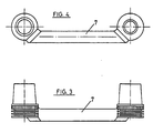
- Figure 3 is an elevational view of the terminals of the same polarity which are connected together by means of a connection bar or bridge,
- Figure 4 is a bottom view of the terminals of Figure 3, and
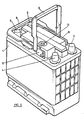
- Figure 5 is a perspective view of a battery constructed in accordance with the present invention, having a handle in the working position and another in the stacking position.
- As shown in the drawings, the battery comprises a
case 1, having a rectangular right prismatic shape, closed at its upper part by acover 2. - This cover, in accordance with the present invention, has passing therethrough four terminals designated by the
reference numbers cover 2. - Each of these terminals situated on a different lateral side,
terminals 3 and 4 on one side andterminals bridge 7 made from the same material or alloy as the grids of the plates of the battery, one of these pairs of terminals being connected to the positive grid and the other pair of terminals to the negative grid. Thus, on both sides of the battery two terminals are provided,terminals 3 and 4 on the one side andterminals - Figures 3 and 4 show two of the terminals of the same polarity connected together by means of the electric connection bar or
bridge 7, situated below thecover 2 of the battery. - From
cover 2 of the battery project outwardly two walls orflanges 8, each of which is placed parallel to and adjacent one of the large sides ofcover 2. On these walls or flanges are hingedly mounted twoequal handles 9 in the form of a C and connected by the end of theirlateral legs 10 towalls 8 by means ofpivots 11 which serve as pivot pins. The pivots which connect the ends of the legs of each handle are aligned, defining with the pivots of the two handles two axes parallel to each other and to cover 2. - In this configuration, the
handles 9 may be disposed in a position folded back againstcover 2, in which position they are shown in Figures 1 and 2, while defining a platform or upper bearingsurface 12, Figure 2, which is situated above the connection terminals while serving as protective element therefor and further allowing the batteries to be stacked on each other. For this reason, thehandles 9 have a lower most bearing position, in which they are in a coplanar situation, as shown in Figure 2. By raisinghandles 9, they may occupy a position substantially parallel and perpendicular to cover 2 so as to be used as handles for handling and transporting the batteries. - The battery of the invention may also be provided with an optical or
electronic detector 13 for showing at all times the chage of the battery and the level of the electrolyte.
Claims (3)
Priority Applications (1)
| Application Number | Priority Date | Filing Date | Title |
|---|---|---|---|
| AT85401930T ATE60854T1 (en) | 1985-07-22 | 1985-10-03 | ELECTRIC ACCUMULATOR BATTERY. |
Applications Claiming Priority (2)
| Application Number | Priority Date | Filing Date | Title |
|---|---|---|---|
| ES545458 | 1985-07-22 | ||
| ES545458A ES8609823A1 (en) | 1985-07-22 | 1985-07-22 | Electric accumulator battery. |
Publications (2)
| Publication Number | Publication Date |
|---|---|
| EP0210317A1 EP0210317A1 (en) | 1987-02-04 |
| EP0210317B1 true EP0210317B1 (en) | 1991-02-06 |
Family
ID=8489582
Family Applications (1)
| Application Number | Title | Priority Date | Filing Date |
|---|---|---|---|
| EP85401930A Expired - Lifetime EP0210317B1 (en) | 1985-07-22 | 1985-10-03 | Electric accumulator battery |
Country Status (20)
| Country | Link |
|---|---|
| US (1) | US4634642A (en) |
| EP (1) | EP0210317B1 (en) |
| JP (1) | JPS6226760A (en) |
| CN (1) | CN1010630B (en) |
| AT (1) | ATE60854T1 (en) |
| BE (1) | BE903907A (en) |
| DE (3) | DE3581735D1 (en) |
| DK (1) | DK449985A (en) |
| EG (1) | EG17899A (en) |
| ES (1) | ES8609823A1 (en) |
| FR (2) | FR2585186B3 (en) |
| GR (1) | GR860349B (en) |
| IE (1) | IE57049B1 (en) |
| IN (1) | IN167672B (en) |
| IT (2) | IT206289Z2 (en) |
| LU (1) | LU86223A1 (en) |
| MA (1) | MA20740A1 (en) |
| PT (1) | PT81337B (en) |
| SU (1) | SU1708167A3 (en) |
| TN (1) | TNSN86107A1 (en) |
Cited By (2)
| Publication number | Priority date | Publication date | Assignee | Title |
|---|---|---|---|---|
| EP0280964A1 (en) * | 1987-03-02 | 1988-09-07 | GLAHAG Beteiligungs AG | Universal battery |
| EP0499035A1 (en) * | 1991-02-13 | 1992-08-19 | VB Autobatterie GmbH | Accumulateur battery with carrying handles |
Families Citing this family (25)
| Publication number | Priority date | Publication date | Assignee | Title |
|---|---|---|---|---|
| AT389596B (en) * | 1987-02-25 | 1989-12-27 | Semperit Ag | BATTERY COVER WITH HANDLES |
| US4752543A (en) * | 1987-04-02 | 1988-06-21 | Anderson Carl J | Universal terminal storage battery with handle |
| US4983473A (en) * | 1989-06-16 | 1991-01-08 | Smith James L | Auxiliary power source with charger and integral light source |
| US5075182A (en) * | 1990-04-27 | 1991-12-24 | Weber Eugene W | Battery holder battery handle and battery indicator |
| JP3304209B2 (en) * | 1994-09-14 | 2002-07-22 | シャープ株式会社 | Charging device |
| DE19528167C1 (en) * | 1995-08-01 | 1996-08-29 | Wolf Geraete Gmbh Vertrieb | Lawn mower with battery charged electric motor |
| US6022638A (en) * | 1997-05-20 | 2000-02-08 | Gnb Technologies, Inc. | Lead-acid battery with handle |
| DE29720115U1 (en) * | 1997-11-13 | 1998-01-02 | Hoppecke Zoellner Sohn Accu | Handle system for accumulators |
| US6183903B1 (en) | 1998-02-03 | 2001-02-06 | Gnb Technologies, Inc. | Plastic battery container having reduced end wall deflection |
| GB9802362D0 (en) * | 1998-02-04 | 1998-04-01 | Chloride Ind Batteries Limited | Battery |
| US5985482A (en) * | 1998-04-28 | 1999-11-16 | Gnb Technologies, Inc. | Snap-on battery heat shield |
| US6300005B1 (en) | 1999-03-17 | 2001-10-09 | Gnb Technologies, Inc. | Battery with container compartment and end wall stiffening block |
| JP3654819B2 (en) * | 2000-06-09 | 2005-06-02 | 矢崎総業株式会社 | Battery cable terminal connection structure |
| CN1268507C (en) * | 2000-09-14 | 2006-08-09 | 本田技研工业株式会社 | Electric auxiliary bicycle and its accumulator holder and accumulator case |
| JP3882174B2 (en) * | 2002-05-15 | 2007-02-14 | 株式会社ジーエス・ユアサコーポレーション | Storage battery |
| TW200830609A (en) * | 2007-01-04 | 2008-07-16 | Wen-Chin Shiau | Double-side usable modularized battery case |
| CN201256161Y (en) * | 2008-08-26 | 2009-06-10 | 广州市凯捷电源实业有限公司 | Replaceable multifunctional enclosed lead acid batteries |
| JP5436850B2 (en) * | 2008-12-19 | 2014-03-05 | 株式会社マキタ | Power tool battery pack |
| EP2556550B1 (en) * | 2010-04-08 | 2017-06-21 | Johnson Controls Technology Company | Battery handle and cover with pivot cam feature, and method of assembly |
| EP2421066B1 (en) * | 2010-08-19 | 2012-10-17 | Alfa Kutu VE Plastik San. VE TIC., Ltd. | Accumulator cover with self locking handle mechanism |
| DE102010040183A1 (en) * | 2010-09-02 | 2012-03-08 | Robert Bosch Gmbh | Multi-part housing |
| USD665343S1 (en) | 2011-10-28 | 2012-08-14 | Exide Technologies | Battery container |
| USD665342S1 (en) | 2011-10-28 | 2012-08-14 | Exide Technologies | Battery container |
| TWD159636S (en) * | 2013-02-08 | 2014-04-01 | 戴健郎 | Lead-acid battery cover |
| US11509188B2 (en) | 2020-02-06 | 2022-11-22 | Caterpillar Inc. | End plate for motor casing |
Family Cites Families (10)
| Publication number | Priority date | Publication date | Assignee | Title |
|---|---|---|---|---|
| US1546648A (en) * | 1923-04-21 | 1925-07-21 | Hood Rubber Co Inc | Handle for hard-rubber battery boxes |
| US1538031A (en) * | 1923-08-03 | 1925-05-19 | Willard Storage Battery Co | Storage-battery container |
| US2170750A (en) * | 1938-02-15 | 1939-08-22 | Royal Battery Corp | Handle or lifting device for storage batteries |
| US3770511A (en) * | 1972-04-25 | 1973-11-06 | Gen Motors Corp | Storage battery having integral cables extending the battery{40 s terminals |
| GB1452102A (en) * | 1973-06-14 | 1976-10-13 | Electric Power Storage Ltd | Electric storage batteries provided with lifting handles |
| US3910800A (en) * | 1974-06-04 | 1975-10-07 | Tudor Ab | Electrical battery |
| DE2741145C2 (en) * | 1977-09-13 | 1979-05-03 | Accumulatorenfabrik Sonnenschein Gmbh, 6470 Buedingen | Carrying device for an accumulator |
| US4350746A (en) * | 1979-04-23 | 1982-09-21 | Chambers Kenneth R | Auxiliary power source for starting a motor vehicle |
| GB2122020B (en) * | 1982-06-10 | 1985-08-14 | Chloride Group Plc | Multicell electric storage batteries |
| US4425414A (en) * | 1982-12-14 | 1984-01-10 | Howard Solomon | Battery |
-
1985
- 1985-07-22 ES ES545458A patent/ES8609823A1/en not_active Expired
- 1985-10-03 DK DK449985A patent/DK449985A/en not_active Application Discontinuation
- 1985-10-03 DE DE8585401930T patent/DE3581735D1/en not_active Expired - Lifetime
- 1985-10-03 AT AT85401930T patent/ATE60854T1/en not_active IP Right Cessation
- 1985-10-03 EP EP85401930A patent/EP0210317B1/en not_active Expired - Lifetime
- 1985-10-08 IE IE2464/85A patent/IE57049B1/en not_active IP Right Cessation
- 1985-10-18 PT PT81337A patent/PT81337B/en not_active IP Right Cessation
- 1985-11-27 US US06/802,365 patent/US4634642A/en not_active Expired - Fee Related
- 1985-12-11 FR FR8518305A patent/FR2585186B3/en not_active Expired
- 1985-12-11 FR FR8518304A patent/FR2585184B3/en not_active Expired
- 1985-12-13 IT IT8554223U patent/IT206289Z2/en active
- 1985-12-13 IT IT8554222U patent/IT206288Z2/en active
- 1985-12-20 LU LU86223A patent/LU86223A1/en unknown
- 1985-12-20 BE BE2/60891A patent/BE903907A/en not_active IP Right Cessation
-
1986
- 1986-01-28 DE DE8602061U patent/DE8602061U1/en not_active Expired
- 1986-01-28 DE DE8602062U patent/DE8602062U1/en not_active Expired
- 1986-02-05 GR GR860349A patent/GR860349B/en unknown
- 1986-06-10 CN CN86103999A patent/CN1010630B/en not_active Expired
- 1986-06-10 JP JP61132902A patent/JPS6226760A/en active Granted
- 1986-06-11 IN IN451/MAS/86A patent/IN167672B/en unknown
- 1986-07-02 SU SU864027752A patent/SU1708167A3/en active
- 1986-07-18 TN TNTNSN86107A patent/TNSN86107A1/en unknown
- 1986-07-21 MA MA20968A patent/MA20740A1/en unknown
- 1986-07-21 EG EG449/86A patent/EG17899A/en active
Cited By (2)
| Publication number | Priority date | Publication date | Assignee | Title |
|---|---|---|---|---|
| EP0280964A1 (en) * | 1987-03-02 | 1988-09-07 | GLAHAG Beteiligungs AG | Universal battery |
| EP0499035A1 (en) * | 1991-02-13 | 1992-08-19 | VB Autobatterie GmbH | Accumulateur battery with carrying handles |
Also Published As
| Publication number | Publication date |
|---|---|
| LU86223A1 (en) | 1986-04-14 |
| JPS6226760A (en) | 1987-02-04 |
| TNSN86107A1 (en) | 1990-01-01 |
| ATE60854T1 (en) | 1991-02-15 |
| DE8602062U1 (en) | 1986-03-06 |
| PT81337A (en) | 1985-11-01 |
| US4634642A (en) | 1987-01-06 |
| FR2585186A3 (en) | 1987-01-23 |
| CN86103999A (en) | 1987-01-21 |
| DE3581735D1 (en) | 1991-03-14 |
| JPH0381261B2 (en) | 1991-12-27 |
| IT8554222V0 (en) | 1985-12-13 |
| IT8554223V0 (en) | 1985-12-13 |
| PT81337B (en) | 1987-09-18 |
| IN167672B (en) | 1990-12-08 |
| ES545458A0 (en) | 1986-09-01 |
| EP0210317A1 (en) | 1987-02-04 |
| DK449985D0 (en) | 1985-10-03 |
| MA20740A1 (en) | 1987-04-01 |
| GR860349B (en) | 1986-09-29 |
| SU1708167A3 (en) | 1992-01-23 |
| DE8602061U1 (en) | 1986-03-13 |
| ES8609823A1 (en) | 1986-09-01 |
| IE852464L (en) | 1987-01-22 |
| IE57049B1 (en) | 1992-04-08 |
| CN1010630B (en) | 1990-11-28 |
| FR2585184A3 (en) | 1987-01-23 |
| EG17899A (en) | 1991-03-30 |
| FR2585186B3 (en) | 1987-08-21 |
| IT206289Z2 (en) | 1987-07-20 |
| IT206288Z2 (en) | 1987-07-20 |
| FR2585184B3 (en) | 1987-08-21 |
| BE903907A (en) | 1986-04-16 |
| DK449985A (en) | 1987-01-23 |
Similar Documents
| Publication | Publication Date | Title |
|---|---|---|
| EP0210317B1 (en) | Electric accumulator battery | |
| US4320183A (en) | Grid for batteries | |
| US5283137A (en) | Cover assembly for rechargeable battery | |
| US4221852A (en) | Radial grids for lead acid batteries | |
| US3871924A (en) | Battery housing with handle for stacking | |
| US4396691A (en) | Battery having separator sheathed/supported plates | |
| JP2001229982A (en) | Set battery and set battery module | |
| US3910800A (en) | Electrical battery | |
| US5001024A (en) | Storage battery and method of manufacturing | |
| US3253962A (en) | Storage battery | |
| US4562128A (en) | Electric storage batteries | |
| US4579790A (en) | Electric storage batteries | |
| US2511943A (en) | Storage battery | |
| EP0195567A2 (en) | Bipolar storage battery | |
| US5874181A (en) | Battery container | |
| EP0251970B1 (en) | An electric storage battery | |
| JPS6217984Y2 (en) | ||
| JPH09245749A (en) | Sealed lead-acid battery | |
| KR200176795Y1 (en) | Multipurpose charger | |
| US6235421B1 (en) | Enclosed lead storage battery | |
| JPH0530286Y2 (en) | ||
| JPS60163380A (en) | Lead-acid battery | |
| JPH0339387B2 (en) | ||
| JPS62190655A (en) | Lead-acid battery | |
| AU3847101A (en) | Low profile six-volt lead-acid battery with front terminals |
Legal Events
| Date | Code | Title | Description |
|---|---|---|---|
| PUAI | Public reference made under article 153(3) epc to a published international application that has entered the european phase |
Free format text: ORIGINAL CODE: 0009012 |
|
| AK | Designated contracting states |
Kind code of ref document: A1 Designated state(s): AT BE CH DE FR GB IT LI LU NL SE |
|
| 17P | Request for examination filed |
Effective date: 19870323 |
|
| 17Q | First examination report despatched |
Effective date: 19880323 |
|
| GRAA | (expected) grant |
Free format text: ORIGINAL CODE: 0009210 |
|
| AK | Designated contracting states |
Kind code of ref document: B1 Designated state(s): AT BE CH DE FR GB IT LI LU NL SE |
|
| REF | Corresponds to: |
Ref document number: 60854 Country of ref document: AT Date of ref document: 19910215 Kind code of ref document: T |
|
| ITF | It: translation for a ep patent filed |
Owner name: JACOBACCI & PERANI S.P.A. |
|
| ET | Fr: translation filed | ||
| REF | Corresponds to: |
Ref document number: 3581735 Country of ref document: DE Date of ref document: 19910314 |
|
| PLBE | No opposition filed within time limit |
Free format text: ORIGINAL CODE: 0009261 |
|
| STAA | Information on the status of an ep patent application or granted ep patent |
Free format text: STATUS: NO OPPOSITION FILED WITHIN TIME LIMIT |
|
| 26N | No opposition filed | ||
| PGFP | Annual fee paid to national office [announced via postgrant information from national office to epo] |
Ref country code: CH Payment date: 19920923 Year of fee payment: 8 |
|
| PGFP | Annual fee paid to national office [announced via postgrant information from national office to epo] |
Ref country code: BE Payment date: 19920930 Year of fee payment: 8 |
|
| PGFP | Annual fee paid to national office [announced via postgrant information from national office to epo] |
Ref country code: GB Payment date: 19921002 Year of fee payment: 8 |
|
| PGFP | Annual fee paid to national office [announced via postgrant information from national office to epo] |
Ref country code: LU Payment date: 19921007 Year of fee payment: 8 |
|
| PGFP | Annual fee paid to national office [announced via postgrant information from national office to epo] |
Ref country code: AT Payment date: 19921012 Year of fee payment: 8 |
|
| PGFP | Annual fee paid to national office [announced via postgrant information from national office to epo] |
Ref country code: FR Payment date: 19921027 Year of fee payment: 8 |
|
| PGFP | Annual fee paid to national office [announced via postgrant information from national office to epo] |
Ref country code: NL Payment date: 19921031 Year of fee payment: 8 |
|
| PGFP | Annual fee paid to national office [announced via postgrant information from national office to epo] |
Ref country code: DE Payment date: 19921126 Year of fee payment: 8 |
|
| EPTA | Lu: last paid annual fee | ||
| PG25 | Lapsed in a contracting state [announced via postgrant information from national office to epo] |
Ref country code: LU Free format text: LAPSE BECAUSE OF NON-PAYMENT OF DUE FEES Effective date: 19931003 Ref country code: GB Effective date: 19931003 Ref country code: AT Effective date: 19931003 |
|
| PGFP | Annual fee paid to national office [announced via postgrant information from national office to epo] |
Ref country code: SE Payment date: 19931005 Year of fee payment: 9 |
|
| PG25 | Lapsed in a contracting state [announced via postgrant information from national office to epo] |
Ref country code: LI Effective date: 19931031 Ref country code: CH Effective date: 19931031 Ref country code: BE Effective date: 19931031 |
|
| BERE | Be: lapsed |
Owner name: S.A. SOCIEDAD ESPANOLA DEL ACUMULADOR TUDOR Effective date: 19931031 |
|
| PG25 | Lapsed in a contracting state [announced via postgrant information from national office to epo] |
Ref country code: NL Effective date: 19940501 |
|
| GBPC | Gb: european patent ceased through non-payment of renewal fee |
Effective date: 19931003 |
|
| NLV4 | Nl: lapsed or anulled due to non-payment of the annual fee | ||
| PG25 | Lapsed in a contracting state [announced via postgrant information from national office to epo] |
Ref country code: FR Effective date: 19940630 |
|
| REG | Reference to a national code |
Ref country code: CH Ref legal event code: PL |
|
| PG25 | Lapsed in a contracting state [announced via postgrant information from national office to epo] |
Ref country code: DE Effective date: 19940701 |
|
| REG | Reference to a national code |
Ref country code: FR Ref legal event code: ST |
|
| PG25 | Lapsed in a contracting state [announced via postgrant information from national office to epo] |
Ref country code: SE Effective date: 19941004 |
|
| EAL | Se: european patent in force in sweden |
Ref document number: 85401930.4 |
|
| EUG | Se: european patent has lapsed |
Ref document number: 85401930.4 |