EP0210289B1 - Bobines de correction supraconductrices pour l'obtention d'un champ magnétique à haute homogénéité - Google Patents
Bobines de correction supraconductrices pour l'obtention d'un champ magnétique à haute homogénéité Download PDFInfo
- Publication number
- EP0210289B1 EP0210289B1 EP85109318A EP85109318A EP0210289B1 EP 0210289 B1 EP0210289 B1 EP 0210289B1 EP 85109318 A EP85109318 A EP 85109318A EP 85109318 A EP85109318 A EP 85109318A EP 0210289 B1 EP0210289 B1 EP 0210289B1
- Authority
- EP
- European Patent Office
- Prior art keywords
- coil
- coils
- filter
- magnetic field
- disposed
- Prior art date
- Legal status (The legal status is an assumption and is not a legal conclusion. Google has not performed a legal analysis and makes no representation as to the accuracy of the status listed.)
- Expired - Lifetime
Links
Images
Classifications
-
- G—PHYSICS
- G01—MEASURING; TESTING
- G01R—MEASURING ELECTRIC VARIABLES; MEASURING MAGNETIC VARIABLES
- G01R33/00—Arrangements or instruments for measuring magnetic variables
- G01R33/20—Arrangements or instruments for measuring magnetic variables involving magnetic resonance
- G01R33/28—Details of apparatus provided for in groups G01R33/44 - G01R33/64
- G01R33/38—Systems for generation, homogenisation or stabilisation of the main or gradient magnetic field
- G01R33/387—Compensation of inhomogeneities
- G01R33/3875—Compensation of inhomogeneities using correction coil assemblies, e.g. active shimming
-
- G—PHYSICS
- G01—MEASURING; TESTING
- G01R—MEASURING ELECTRIC VARIABLES; MEASURING MAGNETIC VARIABLES
- G01R33/00—Arrangements or instruments for measuring magnetic variables
- G01R33/20—Arrangements or instruments for measuring magnetic variables involving magnetic resonance
- G01R33/28—Details of apparatus provided for in groups G01R33/44 - G01R33/64
- G01R33/38—Systems for generation, homogenisation or stabilisation of the main or gradient magnetic field
- G01R33/381—Systems for generation, homogenisation or stabilisation of the main or gradient magnetic field using electromagnets
- G01R33/3815—Systems for generation, homogenisation or stabilisation of the main or gradient magnetic field using electromagnets with superconducting coils, e.g. power supply therefor
-
- G—PHYSICS
- G01—MEASURING; TESTING
- G01R—MEASURING ELECTRIC VARIABLES; MEASURING MAGNETIC VARIABLES
- G01R33/00—Arrangements or instruments for measuring magnetic variables
- G01R33/20—Arrangements or instruments for measuring magnetic variables involving magnetic resonance
- G01R33/28—Details of apparatus provided for in groups G01R33/44 - G01R33/64
- G01R33/42—Screening
- G01R33/421—Screening of main or gradient magnetic field
- G01R33/4215—Screening of main or gradient magnetic field of the gradient magnetic field, e.g. using passive or active shielding of the gradient magnetic field
Definitions
- the present invention relates to magnets and similar means for producing highly uniform, high strength magnetic fields. More particularly, the present invention is related to the construction of magnets for producing high homogeneity magnetic fields for use in nuclear magnetic resonance (NMR) imaging systems.
- NMR nuclear magnetic resonance
- EP-A-0 136 536 discloses a gradient coil having a variation in turns density in the axial direction.
- the magnetic field is important since it establishes nuclear spin precession distribution in the subject volume. Subsequent radio frequency radiation from excited nuclei in this volume are employed, under appropriate circumstances, to produce imaging data and spectroscopic chemical information corresponding to physical objects and processes placed within the volume of interest.
- NMR imaging is particularly applicable to the generation of medical diagnostic images.
- it has been found that it is particularly desirable to employ a highly uniform magnetic field.
- the use of superconductive materials for the construction of high strength, high homogeneity magnets is particularly advantageous.
- superconductive properties may be exploited to provide magnet coils carrying high, persistent currents, often at a level of between about 1,000 and 2,000 amperes.
- the use of superconductive materials has permitted the construction of a magnet for NMR imaging which produces a magnetic field of approximately 1.5 Tesla (15,000 gauss). These high field strengths are particularly advantageous in that the signal to noise ratio in the NMR imaging system is improved.
- superconductive magnets do not require the supply of constant power as do conventional resistive magnets. Furthermore, the important properties of field homogeneity and stability can be better maintained with superconductive magnets than with resistively excited magnet devices. Accordingly, it is seen that it is highly desirable to be able to produce high strength, high uniformity magnetic fields.
- superconductive magnets employed for NMR imaging also typically employ a set of correction coils for the purpose of achieving greater magnetic field uniformity.
- One or more sets of these correction coils may be required.
- the field contribution of a correction coil is designed to be nonuniform, so that in combination with the main magnetic field, the field of the correction coil acts to reduce overall magnetic field non-uniformity.
- Correction coils are typically designed to carry only a small fraction of the current carried by the main superconductive coils. This is a natural consequence of the fact that the correction coils are only designed for producing small correction fields to counter-balance main coil field non-uniformity.
- both the main coils and the correction coils are superconducting
- persistent current switches which are devices which short circuit the coils with an element which is superconductive or resistive at the operator's discretion.
- the switches can be changed to the superconductive state (persistent mode), and the system of coils thereafter preserves its adjustment until it is intentionally disturbed. It should be kept in mind that high field uniformity is an important aspect of the present invention.
- the fundamental method is to distribute the coils so that individually or collectively, they are coupled only to a specific term or specific terms in a series expansion of the field, and that consequently they act to eliminate the specific term or terms.
- a preferred embodiment for the present invention comprises a set of main coils disposed substantially on the surface of a cylindrical support and producing a substantially uniform magnetic field within the support volume, together with at least one short circuited superconducting filter coil, disposed substantially on the surface of a cylindrical support and being disposed so as to reduce specific terms in the cylindrical expansion series representing deviation from magnetic field uniformity.
- at least one of the filter coils is wound so that the surface turn density associated with it is given by sinusoidal or cosinusoidal function of the axial distance from the central area of the cylindrical support.
- an object of the present invention is to provide high strength, high homogeneity magnetic fields.
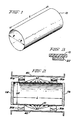
- Figure 2 illustrates a magnet for NMR imaging in accordance with one embodiment of the present invention.
- Metal end caps 11a and 11b shown in Figure 2 are illustrated primarily for the purpose of explaining the theoretical development of the present invention. These end caps are not contemplated as generally being present in NMR imaging systems however.
- the general principle upon which the present invention is based is that closed loop, or short-circuited superconducting coils operate to preserve the net flux linkage through themselves. Advantage is taken of this property to construct specific coils to modify the magnetic field produced by the main coils in order to provide a more spacially uniform magnetic field. As discussed above, spacial uniformity is highly desirable in NMR imaging systems.
- the magnet coil assembly of Figure 2 particularly illustrates the presence of main coils 30a and 30b for providing the greatest contribution to the axially directed magnetic field. Main coils 30a and 30b may or may not, in general, be superconductive. However, it is generally preferred that they are so.
- coil set 20 is the most relevant aspect of Figure 2.
- coil 20 comprises a superconductive coil disposed in a closed loop, that is, short-circuited condition. While a specific short-circuiting connection is not illustrated in Figure 2, it is generally understood that such a connection can be made at any convenient location with a superconductive wire running parallel to the axis of the cylinder. It should also be specifically noted that the axial winding density distribution for coil 20 is not linear.
- Figure 2 illustrates an embodiment of the present invention in which the winding density distribution is (co)sinusoidal.
- the super-conductive components illustrated in Figure 2 are typically disposed within a cryostat structure to contain the coolant and to thermally insulate the structure from ambient temperature conditions.
- cryostat structures are well known and form no part of the present invention, these structures are not shown in the figures.
- Figure 2 illustrates the presence of only a single filter coil on a single cylindrical form, it may be generally desirable to employ several such filter coils on distinct supporting forms. Each such filter coil is designed to eliminate a specific term in an orthogonal function expansion representing deviation of the axial component of the interior magnetic field from spatial uniformity.
- the operation of the apparatus shown in Figure 2 typically takes place in the following manner.
- Superconductive winding set 20 is made to enter the superconductive state by appropriate cooling. The state transition occurs with zero flux through the area bounded by the windings. This area is seen to be approximately ⁇ R2.
- design current levels are established in the main coils. These coils are preferably superconductive. In accordance with well understood mechanisms this current is established with the use of a persistent current switch which comprises superconductive material which may be switched from the resistive or ohmic state to the superconductive state at the will of the operator. It is however understood that time delays in switching occur as a consequence of the thermal nature of the switch.
- Such switches are conventionally connected across the main superconductive windings along with a DC current source. Once the desired current level is reached in the main coil the switch is changed to the superconductive state thereby establishing a closed superconducting loop. The power supply may then be removed.
- filter coil 20 of the present invention is itself a short-circuited loop and there is no need to include a persistent current switch in the filter coil circuit. Accordingly, current flowing in coil 20 arises out of its inductive coupling with the magnetic field flux produced by the main coils. Accordingly, since filter coil 20 is designed for carrying corrective currents to improve magnetic field homogeneity, it need not be designed to carry high levels of current.
- filter coil 20 is now considered, in order to appreciate the particular construction details of filter coils. It should also be born in mind that, while Figure 2 illustrates the utilization of only a single filter coil, additional filter coils may also be employed to correct particular forms of magnetic field inhomogeneity. These particular forms are described in terms of magnetic field expansion series, as is more particularly described below.
- a set of individual superconducting filter coils is defined herein as a set of coils each of which is coupled to one specific term and consequently acts to eliminate that one term in a series expansion of the imposed field, without effect on the other terms of the expansion.
- a set of group superconducting filter coils is also defined as a set of n coils which are collectively coupled to only a specific group of n terms in the expansion and consequently act to eliminate those n terms in the imposed field expansion, again without significant effect on other terms in the expansion.
- the shim coils of the present invention provide another useful approach.
- individual spherical harmonics are not eliminated by special separate filter coils, but rather some groups of spherical harmonics are removed together by corresponding sets of superconducting coils.
- superconducting shim coils can be called "group" filters.
- saddle-shaped filter coils which are located on cylindrical surfaces parallel to axis z can be used. These coils will not be coupled with the axisymmetric components of magnetic induction.
- the filter coils which are located in transverse planes can be used.
- these coils may comprise two parts. These parts should be disposed in two transverse planes symmetrical to each other with respect to the device center. And, these two parts should be connected by transposed conductors.
- the superconducting filters can be used not only for elimination of higher order spherical harmonics created by the main coils. They can be also useful for elimination of distortion of the main magnetic field caused by the secondary (reaction) magnetic field due to a ferromagnetic environment.
- the application of superconductive filter coils makes NMR imaging magnets less sensitive to the type of environment in which they are installed.
- correction coils presently employed in a 0.5 Tesla magnet are designed to have their dominant effect on one particular term of the spherical harmonic expansion of the axial component of the magnetic field. However, they are intended to do so by injection of current from an external source and not by any induced current action. Additionally, in conventional correction coil system design, attention is usually directed to limiting the interaction amongst the correction coils, and to maximizing their effectiveness in creating the intended harmonic terms rather than on their action as superconducting filter elements.
- filter coils based upon spherical harmonic series expansion can not be employed despite the technical difficulties described above. It is nonetheless possible that several such sets of coils, each acting on a different linear combination of spherical harmonic series components can function together to cancel each of several targeted harmonic terms. For high harmonic terms in the series where the level of the harmonic term expected is only barely large enough to require correction, adequate partial cancellation may be obtained.
- Spherical harmonic expansions have long been employed in the NMR imaging arts to characterize the desired field and various perturbing fields.
- spherical harmonic expansions are not the only expansions which may be used to describe the field.
- the spherical harmonic expansion is not very convenient for the purpose of studying superconducting filter coil circuits. It is seen below that an analysis in terms of Bessel functions permits the identification of an idealized filter system on the surface of the cylinder which is just as effective in the idealized form as the one used on the windings on the surface of a sphere.
- the idealized system proposed here requires infinitely permeable end caps on the cylinder. Such end caps are seen as metal discs 11a and 11b in Figure 2.
- This second idealized system represents the best performance which can be achieved by a set of filter coils comprising circular filaments (windings) laying on the surface of a cylinder.
- the error field of this second idealized system is computed knowing only the radial field as a function of radius for the imposed field on the end plane. In this sense, the response of the system is source-independent.
- Equation (1) represents a family of physically admissible fields in a cylinder of radius R and length L. See, for example, Figure 1.
- I0 is a Bessel function of the second kind of order zero.
- the first term in Equation (1) is the term responsible for the desired uniform field. All of the remaining terms represent errors or perturbing fields.
- the potential function V1 of equation (1) represents fields in a cylinder with infinitely permeable end caps, such as those approximated by the end caps shown (for illustration) in Figure 2.
- the potential function represents a second physically admissible family of potential functions.
- J0 represents a Bessel function of the first kind, zeroeth order.
- c n there are several choices for c n which provide useful results.
- the potential function V1 is in the form of a Fourier series in z on the cylindrical surface.
- the potential V2 is an expansion in orthogonal functions on the end planes. A superposition of these two potential functions should be sufficient to match any well behaved and appropriately symmetric potential on the boundary of the cylinder. Thus any field which may exist within the volume due to sources on the surface of or outside the volume may be described by a superposition of these two series.
- Equation (12) The flux linkage for this cosinusoidal winding associated with the field distribution B z ( ⁇ , z) is defined as ⁇ j which may be determined from the following equation: Because of the constraints imposed upon c n in Equation (4) above, and because of the form of the B z field given above in Equation (7), it is seen that the inner or ⁇ -integral in Equation (12) is zero for that portion of the series involving the C n coefficients. Furthermore, because of the orthogonality of the cosine functions in z, only one term survives the outer or z-integration of Equation (12).
- ⁇ j ( ⁇ A j N j L R/(4j)) I1(2 ⁇ jR/L) (13)
- a j is a coefficient from Equation (7) and where I1 is a Bessel function of the second kind, first order. If the amplitude of the A j coefficient is that which corresponds to 1 ampere in a coil having a cos(2 ⁇ jz/L) distribution function, then ⁇ j is the mutual inductance.
- Equation (7) involving terms C n is zero.
- the coil having a cosine (2 ⁇ jz/L) distribution is an example of a perfect filter coil.
- the only flux linked by the coil corresponds to the A j term in the remaining series and the magnitude of the field due to an induced current is at every point equal in magnitude and opposite in sign to the A j component of the applied distribution.
- Equation (13) still holds so that the current in the j th coil is the same as when there are iron ends and the A j term of the applied field, as above.
- the current in the j th coil produces a non-zero C n series and a complete A m series, not just an A j term.
- the unreducible residual error is then represented by the superposition of an infinite number of C-series, one being the C-series of the imposed field, and the rest comprising a C-series for each term in the A-series describing the correction coils.
- the coefficients A m and C m are reserved for the purpose of characterizing and describing the imposed main magnetic field.
- Equation (17) can also be written in the following form: Both sides of Equation (18) may be multiplied by ⁇ J1(c n ⁇ ) and integrated from 0 to R thus resulting in the following: In Equation (19) all but the n th term has been eliminated by the orthogonality properties of the Bessel function.
- equation (20) may be readily solved for E nj as follows: Once the coefficients E nj have been determined, it is a relatively straight forward matter to determine the D m coefficients. First the field along the z-axis is determined for the case of a coil with a cos(2 ⁇ jz/L) distribution.
- the discussion above has primarily been directed to correction filters operating on the axisymmetric components of the magnetic field in question.
- the field error includes significant non-axisymmetric components.
- the non-axisymmetric field can be expanded into a series of potentials having a form very similar to Equations (1) and (2), with the zeroeth order Bessel functions replaced by appropriate higher order Bessel Functions, and with sine and cosine terms in the cylindrical harmonic angle ⁇ multiplying the potentials.
- the component of non-axisymmetric error having sin ⁇ dependence can be described by a set of potentials, as follows:
- the distribution of current on the surface of a cylinder which has properties in this case analogous to that of the (Co) sinusoidal current density in the axisymmetric case, exhibits a current density variation as a sinusoidal function in two dimensions as follows: where the sine and cosine functions for both ⁇ and z may be selected to match the symmetry of the particular non-axisymmetric error component being matched. In general, all terms can be expected to be present. A given coil will nonetheless be specific in its action to cancel a specific term in the F m series, in a manner exactly analogous to the cancellation of a term of the D m series in the case of the axisymmetric field.
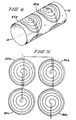
- FIG. 4 illustrates a cylindrical coil form 12 on which saddle coils 25a, 25b, 25c and 25d are disposed.
- the saddle coils are disposed in locations so as to exhibit mirror image symmetry, with respect to their locations at least, with respect to planes, one of which passes through the axis of the coil form and the other of which is perpendicular to the coil form axis and which bisects it substantially in the middle thereof.
- a better appreciation of the design of coils 25a-d may be had through an examination of Figure 5 in which the coils have been isomorphically mapped to a plane.
- the coils illustrated in Figure 4 are fabricated as shown in Figure 5 on a flexible substrate which is then wrapped around a cylindrical coil form of appropriate dimension.
- the dual mirror image symmetry with respect to the centers of each coil is more evident in Figure 5.
- the coils in this embodiment of the present invention are spirally wound but are wound so as to exhibit a sinusoidal variation in turns winding density in both the axial and circumferential directions.
- this variation exhibits itself as a variation in turns density with respect to the direction measured from the center of each spiral coil in the radial direction.
- the non-axisymmetric correction coils are disposed on a separate coil form 12 which is disposed coaxially with respect to coil form 10.
- one of these coil forms is easily seen to slip inside the other to provide an even greater improvement in field homogeneity.
- the present invention provides a means for substantially improving the uniformity of high strength magnetic fields. It is also seen that the present invention provides uniform fields which are useful in NMR imaging applications. It is further seen that the present invention provides filter coils comprising specially designed superconducting current loops which do not require separate power supplies and which operate to automatically correct errors occurring in field uniformity.
Claims (16)
- Aimant pour produire un champ magnétique de haute homogénéité, l'aimant comprenant :
un ensemble de bobines principales (30a, 30b) disposées de façon à produire un champ magnétique sensiblement uniforme dans un volume défini par les bobines principales ; et
au moins une bobine de filtre supraconductrice court-circuitée (20), l'aimant étant caractérisé en ce que la bobine de filtre (20) a une configuration et une disposition propres à présenter une variation sinusoïdale de densité d'enroulement, au moins dans la direction axiale. - Aimant selon la revendication 1, caractérisé en ce que la bobine de filtre (20) est disposée et conformée de façon à éliminer des termes spécifiés dans le développement en série de fonctions orthogonales représentant la variation par rapport à l'homogénéité du champ magnétique dans le volume.
- Aimant selon la revendication 1 ou 2, caractérisé en ce que la bobine de filtre (20) est disposée et conformée de façon à réduire un terme unique du développement en série de fonctions orthogonales représentant la variation par rapport à l'homogénéité du champ dans le volume.
- Aimant selon la revendication 1, 2 ou 3, caractérisé en ce que la bobine de filtre (20) est disposée sensiblement sur la surface d'un support cylindrique, sensiblement coaxialement à l'ensemble de bobines principales (30a, 30b).
- Aimant selon la revendication 1, 2 ou 3, caractérisé en ce que les bobines principales (30a, 30b) sont supraconductrices.
- Aimant selon la revendication 1, 2 ou 3, caractérisé par une pluralité de bobines de filtre (20) qui sont disposées de façon à réduire un groupe spécifique de termes dans un développement en série de fonctions orthogonales représentant la variation par rapport à l'uniformité du champ magnétique.
- Aimant selon la revendication 6, caractérisé en ce que la pluralité de bobines de filtre (20) est disposée de façon à réduire un groupe spécifique de termes dans un développement en série de fonctions cylindriques représentant la variation par rapport à l'uniformité du champ magnétique.
- Aimant selon la revendication 1, dans lequel au moins une bobine de filtre (20) présente une symétrie axiale et dans lequel au moins la jième des bobines de filtre à symétrie axiale est disposée de sorte que la densité d'enroulement en surface associée à la jième bobine de filtre est sensiblement donnée par

où ℓj est une constante pour la jième bobine, L est la longueur axiale de la jième bobine et z est une mesure de la distance dans la direction axiale, z = 0 correspondant à un plan perpendiculaire à l'axe d'un cylindre et passant par la région centrale d'un volume cylindrique formé par les bobines principales (30a, 30b). - Aimant selon la revendication 1, caractérisé en ce qu'au moins une bobine de filtre comprend un ensemble de bobines en selle (25a...25d) comprenant un nombre pair de bobines.
- Aimant selon la revendication 9, caractérisé en ce que l'ensemble de bobines en selle (25a...25d) comprend des bobines à enroulement spiral présentant une variation sinusoïdale de densité d'enroulement dans les directions axiale et circonférentielle.
- Aimant selon la revendication 10, caractérisé en ce que le nombre pair est égal à 4.
- Aimant selon la revendication 9 ou 11, caractérisé en ce que l'ensemble en nombre pair de bobines (25a...25d) présente une symétrie, par rapport à leurs emplacements, autour de deux plans orthogonaux dont l'un comprend l'axe du cylindre et dont l'autre coupe l'axe au point milieu du cylindre.
- Agencement de bobines de filtre, en particulier pour corriger des inhomogénéités spatiales de champ magnétique dans des structures d'aimants supraconducteurs, l'agencement de bobines comprenant au moins une bobine de filtre supraconducteur court-circuitée (20) et étant caractérisé en ce que la bobine de filtre (20) présente une variation sinusoïdale de densité d'enroulement et est disposée de façon à éliminer au moins un terme spécifique du développement en série orthogonale représentant la variation par rapport à une uniformité du champ dans un volume central défini par la bobine de filtre.
- Agencement de bobines de filtre selon la revendication 13, caractérisé en ce que la bobine comprend :
un support de bobine cylindrique (12) ;
au moins une bobine de filtre supraconductrice court-circuitée à symétrie axiale disposée sensiblement sur la surface du support de bobine, au moins la jième des bobines étant disposée de sorte que la densité d'enroulement de surface associée à la jième bobine de filtre est sensiblement donnée par

où ℓj est une constante pour la jième bobine, L est la longueur axiale de la jième bobine et z est une mesure de la distance dans la direction axiale. - Agencement de bobines de filtre selon la revendication 13 ou 14, caractérisé par un ensemble de quatre bobines en selle enroulées en spirale (25a...25d) présentant une variation sinusoïdale de densité d'enroulement dans les directions axiale et circonférentielle.
- Agencement de bobines de filtre selon la revendication 15, caractérisé en ce que l'ensemble de quatre bobines à enroulement spiral (25a...25d) présente une symétrie, par rapport à leur emplacement, autour de deux plans orthogonaux dont l'un comprend l'axe du cylindre et dont l'autre coupe l'axe au point milieu du cylindre.
Priority Applications (2)
| Application Number | Priority Date | Filing Date | Title |
|---|---|---|---|
| DE8585109318T DE3585534D1 (de) | 1985-07-25 | 1985-07-25 | Supraleitende spulen zur magnetfeldkorrektur fuer hohe homogenitaet. |
| EP85109318A EP0210289B1 (fr) | 1985-07-25 | 1985-07-25 | Bobines de correction supraconductrices pour l'obtention d'un champ magnétique à haute homogénéité |
Applications Claiming Priority (1)
| Application Number | Priority Date | Filing Date | Title |
|---|---|---|---|
| EP85109318A EP0210289B1 (fr) | 1985-07-25 | 1985-07-25 | Bobines de correction supraconductrices pour l'obtention d'un champ magnétique à haute homogénéité |
Publications (2)
| Publication Number | Publication Date |
|---|---|
| EP0210289A1 EP0210289A1 (fr) | 1987-02-04 |
| EP0210289B1 true EP0210289B1 (fr) | 1992-03-04 |
Family
ID=8193641
Family Applications (1)
| Application Number | Title | Priority Date | Filing Date |
|---|---|---|---|
| EP85109318A Expired - Lifetime EP0210289B1 (fr) | 1985-07-25 | 1985-07-25 | Bobines de correction supraconductrices pour l'obtention d'un champ magnétique à haute homogénéité |
Country Status (2)
| Country | Link |
|---|---|
| EP (1) | EP0210289B1 (fr) |
| DE (1) | DE3585534D1 (fr) |
Families Citing this family (11)
| Publication number | Priority date | Publication date | Assignee | Title |
|---|---|---|---|---|
| GB8615854D0 (en) * | 1986-06-28 | 1986-08-06 | Turner R | Magnetic field coils |
| CA1331480C (fr) * | 1987-05-18 | 1994-08-16 | Arthur Davidson | Conducteurs a courants intenses et aimants a champs intenses utilisant des supraconducteurs anisotropes |
| US5289128A (en) * | 1992-03-27 | 1994-02-22 | Picker International, Inc. | Superconducting gradient shield coils |
| DE102012215507B3 (de) * | 2012-08-31 | 2013-12-05 | Bruker Biospin Gmbh | Magnetanordnung zum Erzeugen eines hochstabilen Magnetfelds |
| EP3011369B1 (fr) | 2013-06-20 | 2019-12-11 | Aspect International (2015) Private Limited | Système intégré à base de rmn/irm pour une analyse et un traitement d'une boue de forage pour un processus de recyclage de boue de forage et procédés associés |
| US9494503B2 (en) | 2013-11-06 | 2016-11-15 | Aspect Imaging Ltd. | Inline rheology/viscosity, density, and flow rate measurement |
| US10670574B2 (en) | 2015-01-19 | 2020-06-02 | Aspect International (2015) Private Limited | NMR-based systems for crude oil enhancement and methods thereof |
| CN106053299B (zh) | 2015-04-12 | 2020-10-30 | 艾斯拜克特Ai有限公司 | 非圆形横截面管道中的流体的nmr成像 |
| CN106324010A (zh) | 2015-07-02 | 2017-01-11 | 艾斯拜克特Ai有限公司 | 使用mr设备对在管道中流动的流体的分析 |
| US10655996B2 (en) | 2016-04-12 | 2020-05-19 | Aspect Imaging Ltd. | System and method for measuring velocity profiles |
| CN113506668B (zh) * | 2021-06-24 | 2024-03-01 | 北京量子信息科学研究院 | 匀强磁场的产生方法、磁场线圈、装置、设备和存储介质 |
Citations (2)
| Publication number | Priority date | Publication date | Assignee | Title |
|---|---|---|---|---|
| EP0136536A2 (fr) * | 1983-09-06 | 1985-04-10 | General Electric Company | Bobine à gradient de champ magnétique axial utilisée dans un appareil à résonance magnétique nucléaire |
| EP0140259A2 (fr) * | 1983-11-02 | 1985-05-08 | General Electric Company | Bobine à champ graduel transversal |
Family Cites Families (5)
| Publication number | Priority date | Publication date | Assignee | Title |
|---|---|---|---|---|
| US3199021A (en) * | 1960-12-19 | 1965-08-03 | Varian Associates | Apparatus for improving the homogeneity of a magnetic field |
| US3577067A (en) * | 1966-05-11 | 1971-05-04 | Varian Associates | Persistent mode superconductive orthogonal gradient cancelling coils |
| GB2070254B (en) * | 1980-01-21 | 1984-10-17 | Oxford Instr Group Ltd | Nuclear magnetic resonance apparatus and methods |
| US4535291A (en) * | 1982-08-09 | 1985-08-13 | Varian Associates, Inc. | Method for superconducting magnet shimming |
| NL8203756A (nl) * | 1982-09-28 | 1984-04-16 | Holec Nv | Magneetspoeleninrichting. |
-
1985
- 1985-07-25 DE DE8585109318T patent/DE3585534D1/de not_active Expired - Fee Related
- 1985-07-25 EP EP85109318A patent/EP0210289B1/fr not_active Expired - Lifetime
Patent Citations (2)
| Publication number | Priority date | Publication date | Assignee | Title |
|---|---|---|---|---|
| EP0136536A2 (fr) * | 1983-09-06 | 1985-04-10 | General Electric Company | Bobine à gradient de champ magnétique axial utilisée dans un appareil à résonance magnétique nucléaire |
| EP0140259A2 (fr) * | 1983-11-02 | 1985-05-08 | General Electric Company | Bobine à champ graduel transversal |
Also Published As
| Publication number | Publication date |
|---|---|
| EP0210289A1 (fr) | 1987-02-04 |
| DE3585534D1 (de) | 1992-04-09 |
Similar Documents
| Publication | Publication Date | Title |
|---|---|---|
| US4656447A (en) | Superconducting filter coils for high homogeneity magnetic field | |
| EP0136536B1 (fr) | Bobine à gradient de champ magnétique axial utilisée dans un appareil à résonance magnétique nucléaire | |
| JP2581536B2 (ja) | 磁石装置およびその使用方法 | |
| EP0468425B1 (fr) | Système d'aimants | |
| US5721523A (en) | Compact MRI superconducting magnet | |
| CA2115577C (fr) | Bobine electromagnetique blindee de longueur reduite creant un champ ameliore, et methode connexe | |
| EP0210289B1 (fr) | Bobines de correction supraconductrices pour l'obtention d'un champ magnétique à haute homogénéité | |
| US6342787B1 (en) | Real-time multi-axis gradient distortion correction using an interactive shim set | |
| US4728895A (en) | System of coils for producing additional fields for obtaining polarization fields with constant gradients in a magnet having polarization pole pieces for image production by nuclear magnetic resonance | |
| US4658229A (en) | Magnet system providing a region of substantially homogeneous field strength | |
| CH706222B1 (en) | Gradient coil system with correction windings and method for their preparation. | |
| US6351123B1 (en) | Gradient coil system for a magnetic resonance tomography apparatus | |
| JPH0884720A (ja) | 磁気共鳴撮像装置および磁気共鳴撮像装置用の傾斜コイルの設計方法 | |
| US5568110A (en) | Closed MRI magnet having reduced length | |
| CN1266484C (zh) | 具有横向磁场的超导开放mri磁体 | |
| US6084497A (en) | Superconducting magnets | |
| US5594401A (en) | Closed superconductive magnet with uniform imaging volume | |
| US5568102A (en) | Closed superconductive magnet with homogeneous imaging volume | |
| US6100692A (en) | Gradient coil set with a finite shield current | |
| US4931759A (en) | Magnetic resonance imaging magnet having minimally symmetric ferromagnetic shield | |
| EP1338901A1 (fr) | Structure de bobines de gradient pour IRM | |
| US11199599B2 (en) | Magnet assembly comprising closed superconducting HTS shims | |
| CA1258290A (fr) | Bobines de filtrage supraconductrices procurant un champ magnetique homogene intense | |
| JP2593435B2 (ja) | 一様性の高い磁界を発生する磁石 | |
| JPH07250819A (ja) | 受動的にシムを施された側方接近画像形成磁石 |
Legal Events
| Date | Code | Title | Description |
|---|---|---|---|
| PUAI | Public reference made under article 153(3) epc to a published international application that has entered the european phase |
Free format text: ORIGINAL CODE: 0009012 |
|
| AK | Designated contracting states |
Kind code of ref document: A1 Designated state(s): CH DE FR GB IT LI NL SE |
|
| 17P | Request for examination filed |
Effective date: 19870723 |
|
| 17Q | First examination report despatched |
Effective date: 19890117 |
|
| GRAA | (expected) grant |
Free format text: ORIGINAL CODE: 0009210 |
|
| AK | Designated contracting states |
Kind code of ref document: B1 Designated state(s): CH DE FR GB IT LI NL SE |
|
| ITF | It: translation for a ep patent filed |
Owner name: ING. C. GREGORJ S.P.A. |
|
| ET | Fr: translation filed | ||
| REF | Corresponds to: |
Ref document number: 3585534 Country of ref document: DE Date of ref document: 19920409 |
|
| PGFP | Annual fee paid to national office [announced via postgrant information from national office to epo] |
Ref country code: FR Payment date: 19920610 Year of fee payment: 8 |
|
| PGFP | Annual fee paid to national office [announced via postgrant information from national office to epo] |
Ref country code: SE Payment date: 19920615 Year of fee payment: 8 Ref country code: CH Payment date: 19920615 Year of fee payment: 8 |
|
| PGFP | Annual fee paid to national office [announced via postgrant information from national office to epo] |
Ref country code: NL Payment date: 19920731 Year of fee payment: 8 |
|
| REG | Reference to a national code |
Ref country code: GB Ref legal event code: 746 |
|
| ITPR | It: changes in ownership of a european patent |
Owner name: OFFERTA DI LICENZA AL PUBBLICO |
|
| PLBE | No opposition filed within time limit |
Free format text: ORIGINAL CODE: 0009261 |
|
| STAA | Information on the status of an ep patent application or granted ep patent |
Free format text: STATUS: NO OPPOSITION FILED WITHIN TIME LIMIT |
|
| 26N | No opposition filed | ||
| REG | Reference to a national code |
Ref country code: FR Ref legal event code: DL |
|
| PG25 | Lapsed in a contracting state [announced via postgrant information from national office to epo] |
Ref country code: SE Effective date: 19930726 |
|
| PG25 | Lapsed in a contracting state [announced via postgrant information from national office to epo] |
Ref country code: LI Effective date: 19930731 Ref country code: CH Effective date: 19930731 |
|
| PG25 | Lapsed in a contracting state [announced via postgrant information from national office to epo] |
Ref country code: NL Effective date: 19940201 |
|
| NLV4 | Nl: lapsed or anulled due to non-payment of the annual fee | ||
| PG25 | Lapsed in a contracting state [announced via postgrant information from national office to epo] |
Ref country code: FR Effective date: 19940331 |
|
| REG | Reference to a national code |
Ref country code: CH Ref legal event code: PL |
|
| REG | Reference to a national code |
Ref country code: FR Ref legal event code: ST |
|
| EUG | Se: european patent has lapsed |
Ref document number: 85109318.7 Effective date: 19940210 |
|
| REG | Reference to a national code |
Ref country code: GB Ref legal event code: IF02 |
|
| PGFP | Annual fee paid to national office [announced via postgrant information from national office to epo] |
Ref country code: GB Payment date: 20030716 Year of fee payment: 19 |
|
| PGFP | Annual fee paid to national office [announced via postgrant information from national office to epo] |
Ref country code: DE Payment date: 20030731 Year of fee payment: 19 |
|
| PG25 | Lapsed in a contracting state [announced via postgrant information from national office to epo] |
Ref country code: GB Free format text: LAPSE BECAUSE OF NON-PAYMENT OF DUE FEES Effective date: 20040725 |
|
| PG25 | Lapsed in a contracting state [announced via postgrant information from national office to epo] |
Ref country code: DE Free format text: LAPSE BECAUSE OF NON-PAYMENT OF DUE FEES Effective date: 20050201 |
|
| GBPC | Gb: european patent ceased through non-payment of renewal fee |
Effective date: 20040725 |