EP0209908B1 - Apparatus and process for producing carbon black - Google Patents
Apparatus and process for producing carbon black Download PDFInfo
- Publication number
- EP0209908B1 EP0209908B1 EP86110243A EP86110243A EP0209908B1 EP 0209908 B1 EP0209908 B1 EP 0209908B1 EP 86110243 A EP86110243 A EP 86110243A EP 86110243 A EP86110243 A EP 86110243A EP 0209908 B1 EP0209908 B1 EP 0209908B1
- Authority
- EP
- European Patent Office
- Prior art keywords
- zone
- reactor
- reaction
- throat
- range
- Prior art date
- Legal status (The legal status is an assumption and is not a legal conclusion. Google has not performed a legal analysis and makes no representation as to the accuracy of the status listed.)
- Expired - Lifetime
Links
- 239000006229 carbon black Substances 0.000 title claims abstract description 34
- 238000000034 method Methods 0.000 title claims description 19
- 238000006243 chemical reaction Methods 0.000 claims abstract description 79
- 238000011144 upstream manufacturing Methods 0.000 claims abstract description 25
- 238000010791 quenching Methods 0.000 claims description 47
- 238000002485 combustion reaction Methods 0.000 claims description 20
- 239000000567 combustion gas Substances 0.000 claims description 18
- 239000011541 reaction mixture Substances 0.000 claims description 15
- 239000007789 gas Substances 0.000 claims description 13
- 239000000446 fuel Substances 0.000 claims description 8
- 238000002347 injection Methods 0.000 claims description 8
- 239000007924 injection Substances 0.000 claims description 8
- QVGXLLKOCUKJST-UHFFFAOYSA-N atomic oxygen Chemical compound [O] QVGXLLKOCUKJST-UHFFFAOYSA-N 0.000 claims description 7
- 229910052760 oxygen Inorganic materials 0.000 claims description 7
- 239000001301 oxygen Substances 0.000 claims description 7
- 239000012530 fluid Substances 0.000 claims description 6
- 239000007921 spray Substances 0.000 claims description 5
- 239000004215 Carbon black (E152) Substances 0.000 claims description 3
- 230000015572 biosynthetic process Effects 0.000 claims description 3
- 229930195733 hydrocarbon Natural products 0.000 claims description 3
- 150000002430 hydrocarbons Chemical class 0.000 claims description 3
- 235000019241 carbon black Nutrition 0.000 description 26
- 239000000047 product Substances 0.000 description 8
- 101100194706 Mus musculus Arhgap32 gene Proteins 0.000 description 7
- OKTJSMMVPCPJKN-UHFFFAOYSA-N Carbon Chemical compound [C] OKTJSMMVPCPJKN-UHFFFAOYSA-N 0.000 description 6
- 229910052799 carbon Inorganic materials 0.000 description 6
- LZZYPRNAOMGNLH-UHFFFAOYSA-M Cetrimonium bromide Chemical compound [Br-].CCCCCCCCCCCCCCCC[N+](C)(C)C LZZYPRNAOMGNLH-UHFFFAOYSA-M 0.000 description 5
- VNWKTOKETHGBQD-UHFFFAOYSA-N methane Chemical compound C VNWKTOKETHGBQD-UHFFFAOYSA-N 0.000 description 4
- 238000004519 manufacturing process Methods 0.000 description 3
- 238000013329 compounding Methods 0.000 description 2
- 239000003345 natural gas Substances 0.000 description 2
- 239000002245 particle Substances 0.000 description 2
- 238000000197 pyrolysis Methods 0.000 description 2
- 229910021384 soft carbon Inorganic materials 0.000 description 2
- 230000002411 adverse Effects 0.000 description 1
- 230000001427 coherent effect Effects 0.000 description 1
- 238000001816 cooling Methods 0.000 description 1
- 230000001419 dependent effect Effects 0.000 description 1
- 230000008021 deposition Effects 0.000 description 1
- 238000009826 distribution Methods 0.000 description 1
- 230000003628 erosive effect Effects 0.000 description 1
- 238000002474 experimental method Methods 0.000 description 1
- 239000012467 final product Substances 0.000 description 1
- 229910021385 hard carbon Inorganic materials 0.000 description 1
- 239000007788 liquid Substances 0.000 description 1
- 230000000171 quenching effect Effects 0.000 description 1
- 239000011819 refractory material Substances 0.000 description 1
- XLYOFNOQVPJJNP-UHFFFAOYSA-N water Substances O XLYOFNOQVPJJNP-UHFFFAOYSA-N 0.000 description 1
Images
Classifications
-
- C—CHEMISTRY; METALLURGY
- C09—DYES; PAINTS; POLISHES; NATURAL RESINS; ADHESIVES; COMPOSITIONS NOT OTHERWISE PROVIDED FOR; APPLICATIONS OF MATERIALS NOT OTHERWISE PROVIDED FOR
- C09C—TREATMENT OF INORGANIC MATERIALS, OTHER THAN FIBROUS FILLERS, TO ENHANCE THEIR PIGMENTING OR FILLING PROPERTIES ; PREPARATION OF CARBON BLACK ; PREPARATION OF INORGANIC MATERIALS WHICH ARE NO SINGLE CHEMICAL COMPOUNDS AND WHICH ARE MAINLY USED AS PIGMENTS OR FILLERS
- C09C1/00—Treatment of specific inorganic materials other than fibrous fillers; Preparation of carbon black
- C09C1/44—Carbon
- C09C1/48—Carbon black
- C09C1/50—Furnace black ; Preparation thereof
-
- C—CHEMISTRY; METALLURGY
- C01—INORGANIC CHEMISTRY
- C01P—INDEXING SCHEME RELATING TO STRUCTURAL AND PHYSICAL ASPECTS OF SOLID INORGANIC COMPOUNDS
- C01P2006/00—Physical properties of inorganic compounds
- C01P2006/12—Surface area
Definitions
- the invention relates to a process for producing carbon black. In another aspect, the invention relates to an apparatus for producing carbon black.
- Hard or tread type carbon blacks having a surface area in the range of from about 70 to about 125 m2/g as measured by the CTAB method are usually produced by using a different process and reactor than that used for the production of "soft" or carcass type carbon black having a CTAB surface area in the range of about 25 to about 70 m2/g.
- the necessity of having different reactors for different products is burdensome for carbon black plants and the desirability of a single reactor which could produce both types of blacks is manifest.
- the yield of "soft" carbon black on the basis of oil feedstock used is generally lower than theoretical yield. A soft black reactor that provides higher yield or efficiency could provide cheaper product, and would thus be very desirable.
- Grit is another problem in carbon black production. High grit levels in the carbon black product sometimes requires the purchase of micropulverizers as plant equipment. Grit is believed by some to have an adverse impact on compounding carbon black into rubber as well as eroding compounding equipment. Clearly a reactor and process that provide low grit levels in the carbon black product would be desirable.
- a reactor which operates in a stable manner is clearly very desirable.
- the various process inputs must be changed when it is desired to switch over to a new product and the ability to duplicate earlier runs can provide substantial savings in manpower and reduce production of off-specification product.
- a carbon black reactor comprises a refractory sidewall which defines a reaction flow passage having a longitudinal axis.
- a combustion zone and a reactor throat are positioned along the longitudinal axis of the reactor and a converging zone converges from the combustion zone to the reactor throat.
- a quench zone is spaced apart from the reactor throat and has a cross sectional dimension of at least three times the cross sectional dimension of the reactor throat and a reaction zone connects the reactor throat with the quench zone.
- the reaction zone has a cross sectional dimension less than that of the quench zone and in the range of 1.2 to 3 throat diameters.
- the reaction zone has a length in the range of from 2 to 6 throat diameters.
- a first annular and or near annular wall connects the reactor throat with the reaction zone.
- a second annular or near annular wall connects the reaction zone with the quench zone.
- a burner is operably associated with the combustion zone to cause axial flow of hot combustion gases from the combustion zone to the quench zone.
- At least one port for receiving an oil injector for introducing a carbonaceous feedstock radially inwardly toward the longitudinal axis of the reaction flow passage is provided through the side wall of the converging zone.
- Another at least one port for receiving an oil injector for introducing a carbonaceous feedstock generally radially inwardly toward the longitudinal axis of the reaction flow passage is provided through the side wall of the reaction zone.
- the reactor is further provided with a means for introducing quench fluid into the quench zone.
- a process for producing carbon black.
- a hydrocarbon fuel is combusted with an excess amount of oxygen-containing gas to form a mass of hot combustion gases.
- These hot combustion gases are flowed through a converging zone and a carbonaceous feedstock is introduced generally radially inwardly into the hot combustion gases from the periphery of the converging zone to form a first reaction mixture.
- the first reaction mixture flows through a reactor throat, past an abrupt expansion zone in the reaction flow passage at the downstream end of the throat and into the upstream end of a reaction zone.
- reaction zone additional carbonaceous feedstock is introduced generally radially inwardly from the periphery of the reaction zone to form a second reaction mixture and the second reaction mixture is flowed past an abrupt expansion in the reaction flow passage at the downstream end of the reaction zone and into a quench zone which has a sufficiently large diameter and length to provide for the formation of the carbon black.
- the process can be carried out in the above described reactor if desired to produce both hard and soft blacks as desired with low levels of grit and high efficiencies.
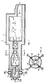
- FIGURE 1 illustrates a cross-sectional view of a carbon black reactor embodying certain features of the present invention.
- FIGURE 2 is a cross-sectional view of the reactor in FIGURE 1 along lines 2-2 of FIGURE 1.
- a carbon black reactor 2 comprises a refractory sidewall 4 for defining a reaction flow passage 6 having a plurality of zones positioned along a longitudinal axis 8.
- the sidewall 4 determines a combustion zone 10 and a reactor throat 12.
- a converging zone 14 converges from the combustion zone 10 to the reactor throat 12.
- a quench zone 16 is provided which has a cross sectional dimension of at least three times the cross sectional dimension of the reactor throat 12.
- a reaction zone 18 connects the reactor throat 12 with the quench zone 16.
- the reaction zone 18 has a cross sectional dimension less than that of the quench zone 16 and in the range of from about 1.2 to 3 throat diameters.
- the length of the reaction zone 18 is in the range of from 1 to 6 throat diameters.
- a first annular or near annular wall 20 connects the reactor throat 12 with the reaction zone 18.
- a second annular or near annular wall 22 connects the reaction zone 18 with the quench zone 16.
- a burner 24 is positioned for axial flow of combustion gases from the combustion zone 10 to the quench zone 16.
- At least one port for an oil injector 26 is provided for introducing a carbonaceous feedstock generally radially inwardly toward the longitudinal axis 8 of the reaction flow passage from the side wall of the converging zone 14.
- At least one port for an oil injector 28 is provided for introducing carbonaceous feedstock generally radially inwardly toward the longitudinal axis 8 of the reaction flow passage from the sidewall of the reaction zone 18.
- the reactor further comprises a means 30 for introducing a quench fluid into the quench zone.
- oxygen-containing gases can be introduced tangentially or radially into the reaction flow passage via one or more of the following: at least one tunnel 32 positioned at the upstream end of the combustion zone 10; at least one tunnel 34 positioned at the upstream end of the reaction zone 18; and/or via at least one tunnel 36 at the upstream end of the quench zone 16.
- Secondary air can also be introduced into the quench zone 16 if desired in a radial or tangential manner. For example, a radial tunnel 38 is shown emptying into the quench zone 16.
- the combustion zone 10 has a generally cylindrical shape and a length in the range of from 2 to 5 reactor throat diameters.
- the converging zone 14 has a frustoconical shape and a length in the range of from 2 to 5 throat diameters.
- the reactor throat has a length in the range of from 0.2 to 2 reactor throat diameters, preferably 0.2-0.7 throat diameters.
- at least two oil injectors 26 are positioned longitudinally spaced apart in the converging zone 14 and at least one oil injector is positioned in the reaction zone 18 through ports in the refractory material. Each of the oil injectors 26 is perfectly radially inwardly directed.
- the oil injectors in the converging zone are preferably located at a first longitudinal position with respect to the reaction flow passage and a second longitudinal position with respect to the reaction flow passage.
- the at least one generally radially inwardly directed oil injector in the reaction zone is positioned at a third longitudinal position with respect to the reactor axis.
- the reaction zone 18 usually has a diameter in the range of from about 1.3 to about 2.7 times the diameter of the reactor throat.
- the reaction zone 18 will usually have a length sufficiently short so that the reacting mass is emitted from it before carbon forming reaction is complete.
- a preferable length for the reaction zone 18 is in the range of from 2 to 5 reactor throat diameters.
- the first wall 20 which connects the reaction zone with the reactor throat is annularly shaped.
- the wall 22 is also annularly shaped.
- the annularly shaped walls provide advantage by assisting in the disassociation of the oil particles for efficient pyrolysis.
- the diameter of the reactor throat 12 will usually be in the range of from 5 to 10 inches.
- the burner 24 is axially directed into the combustion zone 10 from an upstream end thereof in a preferred embodiment of the invention. In this manner, hot combustion gases can be caused to flow axially from the combustion zone to the quench zone.
- One suitable burner can be formed by positioning a gas tube 40 in a tunnel 42 at the upstream end of the combustion zone 10. Fuel such as natural gas from a source 44 is emitted from the tube 40 via apertures 41 and is combusted with air from air sources 46. Good air distribution in the tunnel 42 is provided by causing the air from opposed tunnels 50 to flow in an annulus in the upstream direction and around lip 52 of a tubular gas distributor 54.
- the invention provides a process for producing carbon black in a reaction flow passage.
- a hydrocarbon fuel such as from source 44 is combusted with excess amounts of oxygen containing gas such as air from source 46 to form a mass of hot combustion gases.
- These hot combustion gases are flowed through a converging zone such as zone 14.
- a carbonaceous feedstock is introduced generally radially inwardly into the hot combustion gases from the periphery of the converging zone to form a first reaction mixture.
- the first reaction mixture flows through the reactor throat, past an abrupt upstream expansion-zone in the reaction flow passage at the downstream end of the throat and into the upstream end of a reaction zone.
- reaction zone additional carbonaceous feedstock is introduced generally radially inwardly into the reaction mixture from the periphery of the reaction zone to form a second reaction mixture and this second reaction mixture flows past the second expansion in the reaction flow passage 6 and into a quench zone 16.
- the quench zone 16 has a sufficiently large diameter and a length to provide for the formation of carbon black from the resulting pyrolysis of the second reaction mixture.
- oxygen-containing gas which is usually air
- fuel which is preferably natural gas although oil can also be used
- carbonaceous feedstock such as a residual oil having a high carbon content as measured, for example, by BMCI
- R is the radius of the reactor throat in inches
- the combustion gas flow rate is usually in the range of from about 9,000 R2 to 25,000 R2, preferably in the range 11,000 R2-19,000 R2, the combustion gas flow rate being expressed in terms of standard cubic feet per hour (SCFH) at 1 atmosphere and 60°F. Hard blacks are better produced at the higher flow rates in the range.
- the charge rate of the carbonaceous feedstock is dependent upon the type of carbon black desired, the air/fuel ratio, the oil BMCI value, etc.
- the oil rate will usually provide an air/oil ratio in the range of 250:1 to 750:1 SCF/Gal.
- the most upstream position of carbonaceous feedstock injection will generally be separated from the most downstream position by distance in the range of from 2 to about 7 throat diameters.
- the distance separating the most upstream from the most downstream position of carbonaceous feedstock injection will be in the range of from 3 to 6 reactor throat diameters so that the oil from the downstream injector contacts reactive particles from the upstream injector(s). Based on the examples herein, it appears that best results are obtained when combusting the fuel with from 100 to 150%, for example, about 120%, of the amount of oxygen-containing gas required for stoichiometric combustion.
- oil injectors with spray tips so that a cone-shaped spray of feedstock is emitted from each produces black at higher efficiency than where coherent jets of feed are used although the present invention is not limited to sprays or jets of feedstock.
- oil injector each emit a cone-shaped spray of feedstock.
- a wide cone angle is preferred, such as a cone angle in the range of from 60 to 120°.
- the quench fluid is usually supplied to the quench zone in an amount sufficient to reduce the temperature of the reactor gases to below about 1800°F and terminate the carbon forming reaction.
- the quench fluid will be introduced at a distance in the range of from about 10 to about 30 throat diameters from the outlet of the reactor throat.
- the photolometer of the carbon black product can be controlled. It is important that the quench zone 16 not be so large that liquid water begins to accumulate therein because of low gas velocities. There is thus a practical upper limit to the diameter of the quench zone 18 which can be varied to some extent by the use of bifluid nozzles for the introduction of quench fluid for example.
- the reaction zone has a diameter in the range of from 1.1 to 3.0 throat diameters and the quench zone has a diameter in the range of from 3 to 10 reactor throat diameters.
- the reaction zone had a diameter of about 1.8 times the throat diameter and the quench zone had a diameter of about 6.7 times the throat diameter.
- the lower limit to the diameter of the quench zone is set by the occurrence of carbon deposits.
- the reactor effluent can be withdrawn via tail pipe 62 and processed in conventional equipment.
- Runs were made in a pilot plant sized apparatus similar to that shown in FIGURES 1 and 2.
- the reactor throat had a diameter of 1.7 inches.
- the reaction zone had a diameter of 3 inches.
- the quench zone had a diameter of 12 inches.
- the throat was 1 inch long.
- the reaction zone was 6 inches long.
- An axial nozzle was positioned about 15 feet downstream from the throat outlet. Radial oil injection was selected from positions 4 inches upstream from the throat outlet (4), 2 inches upstream from throat outlet (2), and 41 ⁇ 2 inches downstream from throat outlet (-5). The oil was emitted through orifices ranging from 0.028" to 0.046" as shown.
- a two-stage converging zone was employed, the upstream stage had an upstream diameter of 6.0" and a length of 2" to a downstream diameter of 4.5".
- the downstream portion had an upstream diameter of 4.5" and a length of 13" to a downstream diameter at the throat of 1.7".
Landscapes
- Chemical & Material Sciences (AREA)
- Organic Chemistry (AREA)
- Pigments, Carbon Blacks, Or Wood Stains (AREA)
- Glass Compositions (AREA)
- Physical Or Chemical Processes And Apparatus (AREA)
Priority Applications (1)
| Application Number | Priority Date | Filing Date | Title |
|---|---|---|---|
| AT86110243T ATE100124T1 (de) | 1985-07-26 | 1986-07-25 | Vorrichtung und verfahren zur herstellung von russ. |
Applications Claiming Priority (2)
| Application Number | Priority Date | Filing Date | Title |
|---|---|---|---|
| US759376 | 1985-07-26 | ||
| US06/759,376 US4822588A (en) | 1985-07-26 | 1985-07-26 | Process for producing carbon black |
Publications (3)
| Publication Number | Publication Date |
|---|---|
| EP0209908A2 EP0209908A2 (en) | 1987-01-28 |
| EP0209908A3 EP0209908A3 (en) | 1987-09-23 |
| EP0209908B1 true EP0209908B1 (en) | 1994-01-12 |
Family
ID=25055411
Family Applications (1)
| Application Number | Title | Priority Date | Filing Date |
|---|---|---|---|
| EP86110243A Expired - Lifetime EP0209908B1 (en) | 1985-07-26 | 1986-07-25 | Apparatus and process for producing carbon black |
Country Status (11)
| Country | Link |
|---|---|
| US (1) | US4822588A (xx) |
| EP (1) | EP0209908B1 (xx) |
| AT (1) | ATE100124T1 (xx) |
| BR (1) | BR8603529A (xx) |
| CA (1) | CA1300343C (xx) |
| DE (1) | DE3689526T2 (xx) |
| ES (1) | ES2000744A6 (xx) |
| IN (1) | IN165739B (xx) |
| MX (1) | MX164981B (xx) |
| TR (1) | TR22676A (xx) |
| ZA (1) | ZA865276B (xx) |
Cited By (1)
| Publication number | Priority date | Publication date | Assignee | Title |
|---|---|---|---|---|
| DE102008043606A1 (de) | 2008-11-10 | 2010-05-12 | Evonik Degussa Gmbh | Energieeffiziente Anlage zur Herstellung von Ruß, bevorzugt als energetischer Verbund mit Anlagen zur Herstellung von Siliziumdioxid und/oder Silizium |
Families Citing this family (15)
| Publication number | Priority date | Publication date | Assignee | Title |
|---|---|---|---|---|
| US4988493A (en) * | 1987-11-04 | 1991-01-29 | Witco Corporation | Process for producing improved carbon blacks |
| KR920700267A (ko) * | 1989-02-28 | 1992-02-19 | 모리구찌 엔지 | 카본블랙의 제조방법 및 장치 |
| US5264199A (en) * | 1989-03-04 | 1993-11-23 | Mitsubishi Kasei Corporation | Process for producing carbon black |
| US5188806A (en) * | 1991-01-04 | 1993-02-23 | Degussa Ag | Method and apparatus for producing carbon black |
| US5190739A (en) * | 1991-02-27 | 1993-03-02 | Cabot Corporation | Production of carbon blacks |
| JP3003086B2 (ja) * | 1991-04-02 | 2000-01-24 | 三菱化学株式会社 | カーボンブラックの製造方法 |
| JPH04359068A (ja) * | 1991-06-04 | 1992-12-11 | Tokai Carbon Co Ltd | カーボンブラック製造炉 |
| US6348181B1 (en) * | 1993-06-15 | 2002-02-19 | Cabot Corporation | Process for producing carbon blacks |
| US20040071626A1 (en) | 2002-10-09 | 2004-04-15 | Smith Thomas Dale | Reactor and method to produce a wide range of carbon blacks |
| US7829057B2 (en) * | 2004-05-04 | 2010-11-09 | Cabot Corporation | Carbon black and multi-stage process for making same |
| US20070104636A1 (en) * | 2004-05-04 | 2007-05-10 | Kutsovsky Yakov E | Carbon black and multi-stage process for making same |
| CA2567431A1 (en) * | 2005-11-08 | 2007-05-08 | Cabot Corporation | Carbon black and multi-stage process for making same |
| US9370757B2 (en) | 2012-08-21 | 2016-06-21 | Uop Llc | Pyrolytic reactor |
| CA2983470C (en) | 2015-04-30 | 2021-07-06 | Cabot Corporation | Carbon-coated particles |
| KR102620381B1 (ko) | 2021-10-20 | 2024-01-03 | 오씨아이 주식회사 | 고결정성 카본블랙 및 이의 제조방법 |
Family Cites Families (23)
| Publication number | Priority date | Publication date | Assignee | Title |
|---|---|---|---|---|
| US2682450A (en) * | 1950-11-27 | 1954-06-29 | United Carbon Company Inc | Apparatus for producing carbon black |
| US2851337A (en) * | 1951-08-22 | 1958-09-09 | Columbian Carbon | Carbon black process |
| US2781247A (en) * | 1954-01-29 | 1957-02-12 | Phillips Petroleum Co | Carbon black process |
| US3175888A (en) * | 1961-05-29 | 1965-03-30 | Phillips Petroleum Co | Apparatus for producing low structure carbon black |
| US3222136A (en) * | 1962-11-13 | 1965-12-07 | Ashland Oil Inc | Carbon black apparatus |
| US3410660A (en) * | 1965-09-10 | 1968-11-12 | Phillips Petroleum Co | Carbon black reactor and method of making carbon black |
| US3567395A (en) * | 1968-10-21 | 1971-03-02 | Phillips Petroleum Co | Apparatus for producing carbon black |
| US3642446A (en) * | 1969-01-02 | 1972-02-15 | Columbian Carbon | Process and apparatus for the manufacture of carbon blacks having improved dispersion and platewear characteristics |
| ZA713157B (en) * | 1970-06-08 | 1972-01-26 | Cabot Corp | Process and apparatus for producing carbon black |
| US3725103A (en) * | 1971-03-10 | 1973-04-03 | Cabot Corp | Carbon black pigments |
| US3922335A (en) * | 1974-02-25 | 1975-11-25 | Cabot Corp | Process for producing carbon black |
| US3952087A (en) * | 1974-09-13 | 1976-04-20 | Cabot Corporation | Production of high structure carbon blacks |
| US4105750A (en) * | 1976-06-16 | 1978-08-08 | Cabot Corporation | Production of carbon blacks |
| US4077761A (en) * | 1976-08-04 | 1978-03-07 | Sid Richardson Carbon & Gasoline Co. | Carbon black reactor with axial flow burner |
| US4289743A (en) * | 1977-07-01 | 1981-09-15 | Sid Richardson Carbon & Gasoline Co. | Double venturi carbon black reactor system |
| US4294814A (en) * | 1978-04-12 | 1981-10-13 | Phillips Petroleum Company | Carbon black process and reactor |
| US4241022A (en) * | 1978-12-29 | 1980-12-23 | Phillips Petroleum Company | Carbon black for low-hysteresis rubber compositions |
| US4327069A (en) * | 1980-06-25 | 1982-04-27 | Phillips Petroleum Company | Process for making carbon black |
| US4383973A (en) * | 1980-06-25 | 1983-05-17 | Phillips Petroleum Company | Process and apparatus for making carbon black |
| US4370308A (en) * | 1981-05-15 | 1983-01-25 | Cabot Corporation | Production of carbon black |
| US4391789A (en) * | 1982-04-15 | 1983-07-05 | Columbian Chemicals Company | Carbon black process |
| CA1259164A (en) * | 1982-08-30 | 1989-09-12 | E. Webb Henderson | Carbon blacks and method and apparatus for their production |
| US4540560A (en) * | 1982-08-30 | 1985-09-10 | Phillips Petroleum Company | Carbon blacks |
-
1985
- 1985-07-26 US US06/759,376 patent/US4822588A/en not_active Expired - Lifetime
-
1986
- 1986-06-02 CA CA000510585A patent/CA1300343C/en not_active Expired - Lifetime
- 1986-07-15 ZA ZA865276A patent/ZA865276B/xx unknown
- 1986-07-17 IN IN537/CAL/86A patent/IN165739B/en unknown
- 1986-07-22 MX MX3219A patent/MX164981B/es unknown
- 1986-07-23 TR TR32569/86A patent/TR22676A/xx unknown
- 1986-07-24 ES ES8600560A patent/ES2000744A6/es not_active Expired
- 1986-07-25 DE DE86110243T patent/DE3689526T2/de not_active Expired - Lifetime
- 1986-07-25 BR BR8603529A patent/BR8603529A/pt not_active IP Right Cessation
- 1986-07-25 EP EP86110243A patent/EP0209908B1/en not_active Expired - Lifetime
- 1986-07-25 AT AT86110243T patent/ATE100124T1/de not_active IP Right Cessation
Cited By (1)
| Publication number | Priority date | Publication date | Assignee | Title |
|---|---|---|---|---|
| DE102008043606A1 (de) | 2008-11-10 | 2010-05-12 | Evonik Degussa Gmbh | Energieeffiziente Anlage zur Herstellung von Ruß, bevorzugt als energetischer Verbund mit Anlagen zur Herstellung von Siliziumdioxid und/oder Silizium |
Also Published As
| Publication number | Publication date |
|---|---|
| ZA865276B (en) | 1987-03-25 |
| IN165739B (xx) | 1989-12-30 |
| CA1300343C (en) | 1992-05-12 |
| ATE100124T1 (de) | 1994-01-15 |
| DE3689526D1 (de) | 1994-02-24 |
| US4822588A (en) | 1989-04-18 |
| MX164981B (es) | 1992-10-13 |
| DE3689526T2 (de) | 1994-05-05 |
| EP0209908A3 (en) | 1987-09-23 |
| TR22676A (tr) | 1988-02-26 |
| BR8603529A (pt) | 1987-03-04 |
| EP0209908A2 (en) | 1987-01-28 |
| ES2000744A6 (es) | 1988-03-16 |
Similar Documents
| Publication | Publication Date | Title |
|---|---|---|
| EP0209908B1 (en) | Apparatus and process for producing carbon black | |
| US4765964A (en) | Carbon black reactor having a reactor throat | |
| KR100316500B1 (ko) | 카본블랙의제조방법 | |
| US4540560A (en) | Carbon blacks | |
| EP0232495B1 (en) | Atomizing nozzle and method of automisation | |
| US4824643A (en) | Apparatus for producing carbon black | |
| US4383973A (en) | Process and apparatus for making carbon black | |
| KR0181521B1 (ko) | 카본 블랙 생산 방법 | |
| EP0102072B1 (en) | Method and apparatus for the production of carbon blacks | |
| US3701827A (en) | Process and apparatus for the production of large particle-size,low structure carbon black | |
| US4294814A (en) | Carbon black process and reactor | |
| US4339422A (en) | Carbon black manufacture | |
| EP0136629B1 (en) | Novel carbon blacks and method and apparatus for their production | |
| US2961300A (en) | Carbon black furnace and operation | |
| US2890746A (en) | Non premix burner for producing carbon black | |
| US3490870A (en) | Method and apparatus for the production of carbon black | |
| EP0033954A2 (en) | Apparatus and method for producing carbon black | |
| US4164540A (en) | Carbon black reactor | |
| US4486398A (en) | Feedstock nozzle for low tint residual carbon black | |
| US3409406A (en) | Apparatus for the production of carbon black | |
| US4664901A (en) | Process for producing carbon black | |
| US4601892A (en) | Process for producing carbon black | |
| EP0206315A2 (en) | Process and apparatus for producing carbon black | |
| US4826669A (en) | Method for carbon black production | |
| GB1355541A (en) | Carbon black process and apparatus |
Legal Events
| Date | Code | Title | Description |
|---|---|---|---|
| PUAI | Public reference made under article 153(3) epc to a published international application that has entered the european phase |
Free format text: ORIGINAL CODE: 0009012 |
|
| AK | Designated contracting states |
Kind code of ref document: A2 Designated state(s): AT BE CH DE FR GB IT LI LU NL SE |
|
| PUAL | Search report despatched |
Free format text: ORIGINAL CODE: 0009013 |
|
| AK | Designated contracting states |
Kind code of ref document: A3 Designated state(s): AT BE CH DE FR GB IT LI LU NL SE |
|
| 17P | Request for examination filed |
Effective date: 19871105 |
|
| 17Q | First examination report despatched |
Effective date: 19890710 |
|
| GRAA | (expected) grant |
Free format text: ORIGINAL CODE: 0009210 |
|
| AK | Designated contracting states |
Kind code of ref document: B1 Designated state(s): AT BE CH DE FR GB IT LI LU NL SE |
|
| REF | Corresponds to: |
Ref document number: 100124 Country of ref document: AT Date of ref document: 19940115 Kind code of ref document: T |
|
| ITF | It: translation for a ep patent filed | ||
| REF | Corresponds to: |
Ref document number: 3689526 Country of ref document: DE Date of ref document: 19940224 |
|
| ET | Fr: translation filed | ||
| EPTA | Lu: last paid annual fee | ||
| PLBE | No opposition filed within time limit |
Free format text: ORIGINAL CODE: 0009261 |
|
| STAA | Information on the status of an ep patent application or granted ep patent |
Free format text: STATUS: NO OPPOSITION FILED WITHIN TIME LIMIT |
|
| 26N | No opposition filed | ||
| EAL | Se: european patent in force in sweden |
Ref document number: 86110243.2 |
|
| PGFP | Annual fee paid to national office [announced via postgrant information from national office to epo] |
Ref country code: SE Payment date: 19970623 Year of fee payment: 12 |
|
| PGFP | Annual fee paid to national office [announced via postgrant information from national office to epo] |
Ref country code: BE Payment date: 19970624 Year of fee payment: 12 |
|
| PGFP | Annual fee paid to national office [announced via postgrant information from national office to epo] |
Ref country code: CH Payment date: 19970627 Year of fee payment: 12 |
|
| PGFP | Annual fee paid to national office [announced via postgrant information from national office to epo] |
Ref country code: AT Payment date: 19970630 Year of fee payment: 12 |
|
| PGFP | Annual fee paid to national office [announced via postgrant information from national office to epo] |
Ref country code: LU Payment date: 19970710 Year of fee payment: 12 |
|
| PG25 | Lapsed in a contracting state [announced via postgrant information from national office to epo] |
Ref country code: LU Free format text: LAPSE BECAUSE OF NON-PAYMENT OF DUE FEES Effective date: 19980725 Ref country code: AT Free format text: LAPSE BECAUSE OF NON-PAYMENT OF DUE FEES Effective date: 19980725 |
|
| PG25 | Lapsed in a contracting state [announced via postgrant information from national office to epo] |
Ref country code: SE Free format text: LAPSE BECAUSE OF NON-PAYMENT OF DUE FEES Effective date: 19980726 |
|
| PG25 | Lapsed in a contracting state [announced via postgrant information from national office to epo] |
Ref country code: LI Free format text: LAPSE BECAUSE OF NON-PAYMENT OF DUE FEES Effective date: 19980731 Ref country code: BE Free format text: LAPSE BECAUSE OF NON-PAYMENT OF DUE FEES Effective date: 19980731 Ref country code: CH Free format text: LAPSE BECAUSE OF NON-PAYMENT OF DUE FEES Effective date: 19980731 |
|
| BERE | Be: lapsed |
Owner name: DEGUSSA A.G. Effective date: 19980731 |
|
| REG | Reference to a national code |
Ref country code: CH Ref legal event code: PL |
|
| EUG | Se: european patent has lapsed |
Ref document number: 86110243.2 |
|
| REG | Reference to a national code |
Ref country code: GB Ref legal event code: IF02 |
|
| REG | Reference to a national code |
Ref country code: GB Ref legal event code: 732E |
|
| NLS | Nl: assignments of ep-patents |
Owner name: DEGUSSA-HUELS AKTIENGESELLSCHAFT Owner name: DEGUSSA AG |
|
| REG | Reference to a national code |
Ref country code: FR Ref legal event code: TP |
|
| PGFP | Annual fee paid to national office [announced via postgrant information from national office to epo] |
Ref country code: FR Payment date: 20050712 Year of fee payment: 20 |
|
| PGFP | Annual fee paid to national office [announced via postgrant information from national office to epo] |
Ref country code: DE Payment date: 20050714 Year of fee payment: 20 Ref country code: NL Payment date: 20050714 Year of fee payment: 20 |
|
| PGFP | Annual fee paid to national office [announced via postgrant information from national office to epo] |
Ref country code: IT Payment date: 20050718 Year of fee payment: 20 |
|
| PGFP | Annual fee paid to national office [announced via postgrant information from national office to epo] |
Ref country code: GB Payment date: 20050725 Year of fee payment: 20 |
|
| PG25 | Lapsed in a contracting state [announced via postgrant information from national office to epo] |
Ref country code: GB Free format text: LAPSE BECAUSE OF EXPIRATION OF PROTECTION Effective date: 20060724 |
|
| PG25 | Lapsed in a contracting state [announced via postgrant information from national office to epo] |
Ref country code: NL Free format text: LAPSE BECAUSE OF EXPIRATION OF PROTECTION Effective date: 20060725 |
|
| REG | Reference to a national code |
Ref country code: GB Ref legal event code: PE20 |
|
| NLV7 | Nl: ceased due to reaching the maximum lifetime of a patent |
Effective date: 20060725 |