EP0209901A2 - Dirt sucking apparatus - Google Patents
Dirt sucking apparatus Download PDFInfo
- Publication number
- EP0209901A2 EP0209901A2 EP86110135A EP86110135A EP0209901A2 EP 0209901 A2 EP0209901 A2 EP 0209901A2 EP 86110135 A EP86110135 A EP 86110135A EP 86110135 A EP86110135 A EP 86110135A EP 0209901 A2 EP0209901 A2 EP 0209901A2
- Authority
- EP
- European Patent Office
- Prior art keywords
- suction
- dirt
- suction box
- auxiliary
- main
- Prior art date
- Legal status (The legal status is an assumption and is not a legal conclusion. Google has not performed a legal analysis and makes no representation as to the accuracy of the status listed.)
- Ceased
Links
Images

Classifications
-
- A—HUMAN NECESSITIES
- A47—FURNITURE; DOMESTIC ARTICLES OR APPLIANCES; COFFEE MILLS; SPICE MILLS; SUCTION CLEANERS IN GENERAL
- A47L—DOMESTIC WASHING OR CLEANING; SUCTION CLEANERS IN GENERAL
- A47L9/00—Details or accessories of suction cleaners, e.g. mechanical means for controlling the suction or for effecting pulsating action; Storing devices specially adapted to suction cleaners or parts thereof; Carrying-vehicles specially adapted for suction cleaners
- A47L9/28—Installation of the electric equipment, e.g. adaptation or attachment to the suction cleaner; Controlling suction cleaners by electric means
- A47L9/2857—User input or output elements for control, e.g. buttons, switches or displays
-
- A—HUMAN NECESSITIES
- A47—FURNITURE; DOMESTIC ARTICLES OR APPLIANCES; COFFEE MILLS; SPICE MILLS; SUCTION CLEANERS IN GENERAL
- A47L—DOMESTIC WASHING OR CLEANING; SUCTION CLEANERS IN GENERAL
- A47L5/00—Structural features of suction cleaners
- A47L5/12—Structural features of suction cleaners with power-driven air-pumps or air-compressors, e.g. driven by motor vehicle engine vacuum
- A47L5/22—Structural features of suction cleaners with power-driven air-pumps or air-compressors, e.g. driven by motor vehicle engine vacuum with rotary fans
- A47L5/38—Built-in suction cleaner installations, i.e. with fixed tube system to which, at different stations, hoses can be connected
-
- A—HUMAN NECESSITIES
- A47—FURNITURE; DOMESTIC ARTICLES OR APPLIANCES; COFFEE MILLS; SPICE MILLS; SUCTION CLEANERS IN GENERAL
- A47L—DOMESTIC WASHING OR CLEANING; SUCTION CLEANERS IN GENERAL
- A47L9/00—Details or accessories of suction cleaners, e.g. mechanical means for controlling the suction or for effecting pulsating action; Storing devices specially adapted to suction cleaners or parts thereof; Carrying-vehicles specially adapted for suction cleaners
- A47L9/0009—Storing devices ; Supports, stands or holders
- A47L9/0018—Storing devices ; Supports, stands or holders integrated in or removably mounted upon the suction cleaner for storing parts of said suction cleaner
- A47L9/0036—Storing devices ; Supports, stands or holders integrated in or removably mounted upon the suction cleaner for storing parts of said suction cleaner specially adapted for holding the suction hose
-
- A—HUMAN NECESSITIES
- A47—FURNITURE; DOMESTIC ARTICLES OR APPLIANCES; COFFEE MILLS; SPICE MILLS; SUCTION CLEANERS IN GENERAL
- A47L—DOMESTIC WASHING OR CLEANING; SUCTION CLEANERS IN GENERAL
- A47L9/00—Details or accessories of suction cleaners, e.g. mechanical means for controlling the suction or for effecting pulsating action; Storing devices specially adapted to suction cleaners or parts thereof; Carrying-vehicles specially adapted for suction cleaners
- A47L9/24—Hoses or pipes; Hose or pipe couplings
-
- A—HUMAN NECESSITIES
- A47—FURNITURE; DOMESTIC ARTICLES OR APPLIANCES; COFFEE MILLS; SPICE MILLS; SUCTION CLEANERS IN GENERAL
- A47L—DOMESTIC WASHING OR CLEANING; SUCTION CLEANERS IN GENERAL
- A47L9/00—Details or accessories of suction cleaners, e.g. mechanical means for controlling the suction or for effecting pulsating action; Storing devices specially adapted to suction cleaners or parts thereof; Carrying-vehicles specially adapted for suction cleaners
- A47L9/28—Installation of the electric equipment, e.g. adaptation or attachment to the suction cleaner; Controlling suction cleaners by electric means
- A47L9/2836—Installation of the electric equipment, e.g. adaptation or attachment to the suction cleaner; Controlling suction cleaners by electric means characterised by the parts which are controlled
- A47L9/2842—Suction motors or blowers
Definitions
- the invention relates to a dirt suction device with a main suction box, in which by means of at least one main vacuum source that can be switched on and off, a negative pressure can be generated for suctioning dirt through a suction channel that is led out of the suction box, a preferably flexible hose being tightly connected to the outer end of the suction channel is, which is accommodated in at least one loop in a storage box, from which it is guided to the outside through an opening, the edge of which surrounds the outer jacket of the hose.
- Such dirt suction devices are often installed at self-service petrol stations to give vehicle owners the opportunity to clean their vehicle from the inside by means of the flexible hose by guiding the suction pipe of the flexible hose over the floor and the seats of the vehicle. With such dirt suction devices, it is important that the flexible hose is stowed in the non-use position inside the housing of the device or outside at a suitable point in such a way that it is neither in the way nor can it be contaminated.
- a dirt suction device with a main suction box is already known, from which a pipe sucking the dirt is guided into a storage box in which the hose is accommodated to form a loop. From an opening in the front wall of the storage box, the hose provided with an intake socket can be pulled out of the storage box to a desired length. After use, the hose is then pushed back through the opening into the storage box (US Pat. No. 20 51 728).
- the aim of the invention is to provide a dirt suction device of the type mentioned at the beginning, with which the flexible hose is automatically drawn into a space that is completely protected from the outside after use, but at the same time automatic cleaning of the hose areas entering the housing of the device takes place.
- the invention provides that the edge surrounds the outer jacket of the hose with little play and the storage box is designed as an auxiliary suction box in which such a vacuum can be generated that the hose can be pulled out of the opening while reducing the loop against the vacuum and can be pulled into the auxiliary suction box by releasing the vacuum by enlarging the loop.
- the flexible hose insofar as its end piece does not constantly protrude from the device, is stowed in a housing which is tightly sealed on all sides and into which it is automatically sucked in by negative pressure, the being due to the negative pressure in the region of the annular gap
- High-speed suction air on the outer jacket of the flexible hose blows away any dirt or moisture present in this area. Dirt and moisture then collect on the bottom of the auxiliary suction box, from where they can be removed from time to time through a suitable door or flap. Since all areas of the outer casing of the hose must pass through the opening when the flexible hose is sucked into the auxiliary suction box, the hose along its entire outer casing is completely cleaned once in a pulling-in process.
- a stop flange is expediently provided on the hose, which limits the size of the loop.
- a certain piece of hose required for gripping still protrudes from the front wall of the dirt suction device, but it is so short that it cannot come into contact with the ground.
- this piece of hose can also be arranged completely sunk in the auxiliary suction box, so that only the end connector of the flexible hose required for suction protrudes from the front wall of the housing of the dirt suction device according to the invention.
- a signal transmitter is provided on the hose in the region of the flange, which is connected to the opening on the auxiliary suction box interacts with the signal receiver, which is connected via a line to an electrical control circuit by means of which the vacuum in the auxiliary suction box is switched off when the signal transmitter is close to the signal receiver, or is switched on when the signal transmitter is away from the signal receiver.
- the hose In order to make the compressive force acting on the hose when pulling in as large as possible at a given negative pressure inside the auxiliary suction box, the hose should have radially protruding circumferential ribs at small longitudinal intervals, the longitudinal spacings of the circumferential ribs expediently being smaller than the axial length of the opening. In this way, ring surfaces are created in the area of the opening which are essentially perpendicular to the hose axis and on which the differential pressure between the atmosphere and the interior of the auxiliary suction box can act in the sense that the flexible hose is driven into the interior of the auxiliary suction box.
- the vacuum in the auxiliary suction box can be generated by an auxiliary vacuum source.
- the vacuum in the auxiliary suction box can be generated by the main vacuum source by switching off the vacuum from the main suction box and applying it to the auxiliary suction box by means of a valve arrangement. So here are the main suction turbines intended for dirt removal at the same time used for pulling in the flexible hose by means of negative pressure.
- An advantageous practical embodiment is characterized in that a preferably vertical partition is provided between the main suction box and the auxiliary suction box, in which the suction box opens preferably at a medium height.
- a further expedient embodiment is designed such that a preferably horizontal transverse wall is arranged above the main suction box, in which at least one main suction turbine is arranged as the main negative pressure source.
- control circuit and other actuating elements are arranged above the transverse wall.
- a further development of the invention which is essential for a compact arrangement, is characterized in that an auxiliary suction turbine is arranged as an auxiliary vacuum source above the transverse wall in the intermediate wall.
- the invention also seeks to remedy this situation by ensuring that most of the dirt sucked falls into the dirt-collecting container and only as little dirt or dust as possible reaches the filters, which should be as large as possible.
- the invention provides for a dirt suction device according to the preamble of claim 1 that below the main suction turbine (s) with a vertical distance, a horizontally extending baffle plate extending all around beyond the suction openings is provided, below which an open top Dirt collecting container is arranged, into which the intake duct opens from above.
- ring filter packets should be arranged tightly between the transverse wall containing the main suction turbine (s) and the baffle plate.
- the ring filter packs lie with their upper and lower edges close to the transverse wall or the baffle plate.
- the ring filter packs should be essentially rectangular or round.
- each ring filter package consists of filter material folded like an accordion and / or provided with folded filter bags.
- the exit velocity of the dirt-air flow within the dirt-collecting container is relatively high, but due to the comparatively large diameter of the dirt-collecting container, there is a sudden expansion that leads upwards out of the dirt-collecting container escaping air flow considerably and suddenly slowed down so that only a little dirt is carried upwards.
- the baffle plate hits the baffle plate from below and is thus thrown back in the direction of the dirt collecting container.
- the air is deflected at the baffle plate and enters laterally around it into the wall-shaped filter, where there has already been extensive separation of dirt and air.
- the relatively large filter area effectively prevents the filter from clogging quickly due to entrained dust.
- Such dirt suction devices in self-service filling stations are generally triggered by the insertion of a coin.
- the control circuit first starts the main suction turbines for a certain period of time.
- the operator can now pull the hose out of the vacuum suction box and carry out the desired cleaning work.
- the main suction turbines switch off, and at the same time the auxiliary suction turbine is switched on. If the user now releases the hose, it is automatically drawn into the auxiliary suction box, the loop being formed and dirt being removed from the jacket of the hose.
- the suction of the hose then continues until the flange provided on it abuts against the front wall of the housing next to the suction opening, whereupon the signal generator, in cooperation with the signal receiver, switches off the auxiliary suction turbine via the control circuit.
- a preferred embodiment of the invention thus consists in that the control circuit switches off the negative pressure in the auxiliary suction box when the main suction turbines are switched on and switches on the negative pressure in the auxiliary suction box when the main suction turbines are switched off, provided that the signal generator and the signal receiver are separated from one another.
- a preferred practical embodiment is characterized in that the auxiliary suction box extends alongside the main suction box and the receiving space above it over the entire height of the device.
- the hose can be placed in a simple loop inside the vacuum box. In principle, however, it is also possible to form the loop by rolling up the hose, provided that longer, extendable hose lengths are desired.
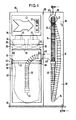
- the dirt suction device according to the invention is accommodated in a cuboid sheet metal or plastic housing 36, which is at the bottom on the floor 37 of a self-service filling station.
- the front wall 38 of the housing 36 has, in its left area in FIG. 1, a removable rectangular flap 39 which is slightly higher than half the height of the housing 36 and whose width is slightly larger than the width of the housing 36. 1 to 3, at about half the height of the housing 36, there is a holding device 40 for a sack-like dirt collecting container 32 on the left side wall 41 in FIG. 1 and on a vertical intermediate wall 29 of the housing 36 intended.
- a clamping frame 42 which holds the dirt collecting container 32 at the top engages in the holding device 40.
- a wall outlet 43 to which a downwardly curved suction hose 13 connects to the dirt collecting container 32, the outlet end 44 of which opens as far down as possible within the dirt collecting container 32.
- a horizontally extending flat baffle plate 31 is fastened in a manner not shown, in addition to which air passage gaps 44 are provided all around.
- a transverse wall 30 extending transversely between the intermediate wall 29 and the side wall 41, which divides the housing 36 into a lower main suction box 11 and an upper receiving space 35 for various actuation and drive elements.
- Two main suction turbines 12 are installed side by side in the transverse wall 30, the suction openings (not shown) of which are surrounded by ring filter packs 33 which consist of filter material folded in the manner shown.
- the ring filter packs 33 lie close to the transverse wall 30 from below and there surround the suction opening of the main suction turbine 12, not shown.
- the ring filter packs 33 lie close to the top of the baffle plate 31 below.
- the air sucked in by the main suction turbines 12 is thus forced to strike the large, wrinkled outer wall 34 of the ring filter package 34 through the wide annular gaps 44.
- the filtered air is then blown out by the main suction turbines 12 in a manner not shown.
- the intake duct 13 which is preferably also designed as a flexible hose, merges into a flexible hose 14 following the feed-through connector 43 and a pipe elbow 45 which is angled downward by 90 ° down and then finally up to a circular passage opening 17 provided in the front wall of the housing 36, where it passes through the front wall from the inside to the outside, and then vertically in the manner shown in FIGS. 1 and 2 hanging down below.
- a suction port 46 is attached at the outer end of the flexible hose 14.
- the flexible hose is provided with circumferential ribs 24 all around at relatively short longitudinal distances.
- the flexible hose 14 has a stop flange 19 all around, which continues in the direction of the loop 15 into a shrink tube piece 46, within which a signal transmitter 20 which is as flat as possible is accommodated, e.g. can be designed as a magnetic or metal plate.
- the material 47 around the opening 17 has a certain extent in the axial direction, which should be greater than the longitudinal spacing of the circumferential ribs 24.
- the dimensioning of the diameter of the opening 17 is selected so that a slight play remains between the circumferential ribs or the shrink tube 46 and the edge 18 of the opening 17.
- the area of the housing 36 on the left in FIG. 7 forms an auxiliary suction box 16 which is continuous from top to bottom and is airtight on all sides except for the opening 17 and which can be placed under negative pressure by an auxiliary suction turbine 25 connected to the intermediate wall 29 at the top right in FIG. 2 .
- the auxiliary suction turbine 25 is connected to the auxiliary suction box 16 through a bore 48.
- a signal receiver 21 which as a switch responding to a metal plate or a magnetic plate, e.g. Reed switch can be formed.
- the signal receiver 21 is connected via a line 22 to a control circuit 23 which is accommodated in the receiving space 35 above the main suction turbines 12.
- the control circuit 23 also switches the main suction turbines 12 and the auxiliary suction turbine 25.
- a further embodiment is also indicated in dash-dotted lines in FIG. 3, in which the main suction turbines 12 are also used to generate the negative pressure in the auxiliary suction box 16, as a result of which the auxiliary suction turbine 25 can be dispensed with.
- a perforated plate 27 can be arranged below the baffle plate 31, which extends over the entire horizontal cross-sectional area of the main suction box 11.
- a perforated slide valve 26 which in the position shown is air passage from bottom to top possible.
- the slide valve 26 is moved by an actuating device 49 in the direction of arrow f in FIG. 3, the holes in the perforated plate 27 and the slide valve 26 become out of alignment, which leads to an airtight seal between the auxiliary suction box 11 and the space above the slide valve 26 leads.
- control circuit 23 excites a further actuating device 50, which opens a flap 28 provided in the intermediate wall 29 and thus establishes a flow connection between the main suction turbines 12 and the auxiliary suction box 16.
- the control circuit 23 controls the flap 28 on the one hand and the hole slide 26 on the other hand such that the main suction turbines 12 are connected either to the main suction box 11 or to the auxiliary suction box 16.
- control circuit 23 switches off the main suction turbines 12 and at the same time switches on the auxiliary suction turbine 25.
- the slide gate 26 are switched into the closing and the flap 28 into the open position, in which case the main suction turbines 12 would continue to run.
- a foam body 53 provided with deep grooves is preferably provided on the base 52, the grooves being so narrow and deep that dust and dirt stripped from the tube 14 can collect therein, but the tube 14 resting on the base 52 does not come into contact with the dust collected in the grooves again, which could otherwise lead to re-contamination. In this way, the flexible hose 14 with the lower sagging loop 15 can rest on the floor 52.
- the flexible hose 14 is sucked in until the flange 19 comes into contact with the front wall of the housing.
- the signal generator 20 switches off the auxiliary suction turbine 25 and the main suction turbine 12 via the signal generator 21 and the control circuit 23.
- auxiliary turbine 25 In the area of the intake opening 48 of the auxiliary turbine 25 there is a prefilter, not shown.
- the pressure generated by the auxiliary turbine 25 is 140 mm WS.
- the signal transmitter 20 and signal receiver 21 can expediently be an inductive proximity switch.
- the can 18 surrounding the inlet opening 17 is expediently designed as a Teflon nozzle.
- the hose 14 is guided through the passage opening 17 with as little play as possible, but the play is dimensioned sufficiently large so that the flexible hose 14 does not get caught in the opening 17 when it is sucked in or pulled out.
- the outlet opening 17 should be provided as far as possible at the top in the front wall of the housing 36, while the transition piece 43 for the connection of the intake duct 13 is arranged at the very front and as high as possible on the intermediate wall 29.
- the intake duct 13 opens directly above the holding device 40 for the dirt collecting container 32.
- the elbow 45 can be pivotable about the horizontal axis 54 common to the connecting piece 43.
- the tube has only a single loop 15 in the drawn-in state from its entry end to its exit end, thereby ensuring that it is drawn in easily.
- the auxiliary suction turbine 25 is expediently switched only by the switching device 20, 21, so that it always runs when the hose is pulled out, i.e. even when the main suction turbine 12 is switched on. Then the extension length can always be automatically adapted to the requirements.
Abstract
Eine Schmutzsaugvorrichtung weist einen Hauptsaugkasten (11) mit einem Schmutzsammelbehälter (32) und einen Hilfsaugkasten (16) mit einem darin in Form einer Schleife (15) gelegten flexiblen Schlauch (14) auf, der durch eine Öffnung (17) in der Vorderwand des Gehäuses (36) nach außen geführt ist. Durch einen Unterdruck in dem Hilfssaugkasten (16) wird der flexible Schlauch (14) automatisch in seine Nichtgebrauchsstellung eingezogen und dabei selbsttätig gereinigt.A dirt suction device has a main suction box (11) with a dirt collecting container (32) and an auxiliary suction box (16) with a flexible hose (14) placed therein in the form of a loop (15) which passes through an opening (17) in the front wall of the housing (36) is led to the outside. Due to a negative pressure in the auxiliary suction box (16), the flexible hose (14) is automatically drawn into its non-use position and thereby cleaned automatically.
Description
Die Erfindung betrifft eine Schmutzsaugvorrichtung mit einem Hauptsaugkasten, in welchem durch wenigstens eine ein- und ausschaltbare Hauptunterdruckquelle ein zum Ansaugen von Schmutz durch einen dicht aus dem Saugkasten herausgeführten Ansaugkanal Unterdruck erzeugt werden kann, wobei an das äußere Ende des Ansaugkanals ein vorzugsweise flexibler Schlauch dicht angeschlossen ist, der in wenigstens einer Schleife in einem Aufbewahrungskasten untergebracht ist, aus dem er durch eine Öffnung, deren Rand den Außenmantel des Schlauches umgibt, nach außen geführt ist.The invention relates to a dirt suction device with a main suction box, in which by means of at least one main vacuum source that can be switched on and off, a negative pressure can be generated for suctioning dirt through a suction channel that is led out of the suction box, a preferably flexible hose being tightly connected to the outer end of the suction channel is, which is accommodated in at least one loop in a storage box, from which it is guided to the outside through an opening, the edge of which surrounds the outer jacket of the hose.
Derartige Schmutzsaugvorrichtungen sind häufig bei Selbstbedienungstankstellen aufgestellt, um den Fahrzeugbesitzern die Möglichkeit zu geben, mittels des flexiblen Schlauches ihr Fahrzeug von innen von Schmutz zu säubern, indem der Ansaugstutzen des flexiblen Schlauches über den Boden und die Sitze des Fahrzeugs geführt wird. Bei derartigen Schmutzsaugvorrichtungen kommt es darauf an, daß der flexible Schlauch in der Nichtgebrauchsposition innerhalb des Gehäuses der Vorrichtung oder außerhalb an geeigneter Stelle derart gestaut wird, daß er weder im Wege steht noch verschmutzt werden kann.Such dirt suction devices are often installed at self-service petrol stations to give vehicle owners the opportunity to clean their vehicle from the inside by means of the flexible hose by guiding the suction pipe of the flexible hose over the floor and the seats of the vehicle. With such dirt suction devices, it is important that the flexible hose is stowed in the non-use position inside the housing of the device or outside at a suitable point in such a way that it is neither in the way nor can it be contaminated.
Es ist bereits bekannt, derartige flexible Schläuche außerhalb des Vorrichtungsgehäuses über eine Spannvorrichtung zu führen, die den flexiblen Schlauch bei Nichtgebrauch in einer Schleife oberhalb des Gehäuses hält. Weiter kann man innerhalb des Gehäuses eine Rollvorrichtung vorsehen, auf die der flexible Schlauch beispielsweise mittels Federkraft nach Gebrauch aufgerollt wird. Beim Ziehen am Schlauchstutzen rollt sich dieser ab und tritt durch eine Führungsöffnung in der Vorderwand des Gehäuses aus diesem in der erwünschten Länge aus (US-PS 42 46 675).It is already known to guide such flexible hoses outside the device housing via a tensioning device, which holds the flexible hose in a loop above the housing when not in use. Furthermore, a rolling device can be provided within the housing, onto which the flexible hose is rolled up after use, for example by means of spring force. When the hose connector is pulled, it rolls off and emerges from the housing in the desired length through a guide opening in the front wall (US Pat. No. 4,246,675).
Weiter ist bereits eine Schmutzsaugvorrichtung mit einem Hauptsaugkasten bekannt, von dem aus ein den Schmutz ansaugendes Rohr in einen Aufbewahrungskasten geführt ist, in welchem der Schlauch unter Bildung einer Schleife untergebracht ist. Aus einer Öffnung in der Vorderwand des Aufbewahrungskastens kann der mit einem Ansaugstutzen versehene Schlauch bis zu einer gewünschten Länge aus dem Aufbewahrungskasten herausgezogen werden. Nach Gebrauch wird der Schlauch dann wieder durch die öffnung in den Aufbewahrungskasten hineingeschoben (US-PS 20 51 728).Furthermore, a dirt suction device with a main suction box is already known, from which a pipe sucking the dirt is guided into a storage box in which the hose is accommodated to form a loop. From an opening in the front wall of the storage box, the hose provided with an intake socket can be pulled out of the storage box to a desired length. After use, the hose is then pushed back through the opening into the storage box (US Pat. No. 20 51 728).
Ein erhebliches Problem bei derartigen Schmutzsaugvorrichtungen besteht in der ständigen Verschmutzung des Schlauches, wenn dieser z.B. mit dem verschmutzten Boden oder verschmutzten Bereichen eines Fahrzeugs in Berührung kommt. Dies bringt dann die Gefahr mit sich, daß die die Saugvorrichtung benutzende Person mit dem verschmutzten Schlauch ihre Kleidung oder das Innere des Fahrzeuges verschmutzt. Es muß auch damit gerechnet werden, daß bestimmte Benutzer der Saugvorrichtung den Schlauch nicht wieder in den Aufbewahrungskasten zurückführen, wodurch dann eine erhöhte Verschmutzungs- und auch Beschädigungsgefahr für den Schlauch besteht.A considerable problem with such dirt suction devices is the constant contamination of the hose when it is e.g. comes into contact with the dirty floor or areas of a vehicle. This then entails the risk that the person using the suction device will dirty his clothes or the interior of the vehicle with the dirty hose. It must also be expected that certain users of the suction device will not return the hose to the storage box, which then increases the risk of contamination and damage to the hose.
Das Ziel der Erfindung besteht darin, eine Schmutzsaugvorrichtpng der eingangs genannten Gattung zu schaffen, mit der einerseits nach Gebrauch der flexible Schlauch selbsttätig in einen nach außen völlig geschützten Raum eingezogen wird, gleichzeitig aber eine automatische Reinigung der in das Gehäuse der Vorrichtung eintretenden Schlauchbereiche erfolgt.The aim of the invention is to provide a dirt suction device of the type mentioned at the beginning, with which the flexible hose is automatically drawn into a space that is completely protected from the outside after use, but at the same time automatic cleaning of the hose areas entering the housing of the device takes place.
Zur Lösung dieser Aufgabe sieht die Erfindung vor, daß der Rand den Außenmantel des Schlauches mit geringem Spiel umgibt und der Aufbewahrungskasten als Hilfssaugkasten ausgebildet ist, in dem ein derartiger Unterdruck erzeugbar ist, daß der Schlauch unter Verkleinerung der Schleife gegen den Unterdruck aus der Öffnung herausziehbar und beim Loslassen unter Vergrößerung der Schleife vom Unterdruck in den Hilfssaugkasten hineinziehbar ist.To achieve this object, the invention provides that the edge surrounds the outer jacket of the hose with little play and the storage box is designed as an auxiliary suction box in which such a vacuum can be generated that the hose can be pulled out of the opening while reducing the loop against the vacuum and can be pulled into the auxiliary suction box by releasing the vacuum by enlarging the loop.
Der Erfindungsgedanke ist also darin zu sehen, daß der flexible Schlauch, soweit sein Endstück nicht ständig aus der Vorrichtung heraussteht, in einem allseits dicht abgeschlossenen Gehäuse gestaut wird, in welches er durch Unterdruck selbsttätig hineingesaugt wird, wobei die aufgrund des Unterdruckes im Bereich des Ringspaltes mit hoher Geschwindigkeit eintretende Saugluft am Außenmantel des flexiblen Schlauches in diesem Bereich vorhandenen Schmutz oder dort vorhandene Feuchtigkeit wegbläst. Schmutz und Feuchtigkeit sammeln sich dann am Boden des Hilfssaugkastens, von wo sie von Zeit zu Zeit durch eine geeignete Tür oder Klappe entfernt werden können. Da beim Einsaugen des flexiblen Schlauches in den Hilfssaugkasten sämtliche Bereiche des Außenmantels des Schlauches durch die öffnung hindurchtreten müssen, wird der Schlauch entlang seines gesamten Außenmantels bei einem Einziehvorgang jeweils einmal völlig gereinigt.Ein weiterer Reinigungsvorgang erfolgt beim Herausziehen.The idea of the invention is therefore to be seen in the fact that the flexible hose, insofar as its end piece does not constantly protrude from the device, is stowed in a housing which is tightly sealed on all sides and into which it is automatically sucked in by negative pressure, the being due to the negative pressure in the region of the annular gap High-speed suction air on the outer jacket of the flexible hose blows away any dirt or moisture present in this area. Dirt and moisture then collect on the bottom of the auxiliary suction box, from where they can be removed from time to time through a suitable door or flap. Since all areas of the outer casing of the hose must pass through the opening when the flexible hose is sucked into the auxiliary suction box, the hose along its entire outer casing is completely cleaned once in a pulling-in process.
Zweckmäßigerweise ist am Schlauch ein AnschlagfDansch vorgesehen, der die Größe der Schleife begrenzt. Auf diese Weise steht noch ein gewisses zum Erfassen erforderliches Schlauchstück von der Vorderwand der Schmutzsaugvorrichtung vor, welches jedoch so kurz ist, daß es nicht mit dem Boden in Berührung kommen kann. Grundsätzlich kann dieses Schlauchstück jedoch ebenfalls völlig in dem Hilfssaugkasten versenkt angeordnet sein, so daß nur der zum Saugen erforderliche Endstutzen des flexiblen Schlauches von der Vorderwand des Gehäuses der erfindungsgemäßen Schmutzsaugvorrichtung vorsteht.A stop flange is expediently provided on the hose, which limits the size of the loop. In this way, a certain piece of hose required for gripping still protrudes from the front wall of the dirt suction device, but it is so short that it cannot come into contact with the ground. In principle, however, this piece of hose can also be arranged completely sunk in the auxiliary suction box, so that only the end connector of the flexible hose required for suction protrudes from the front wall of the housing of the dirt suction device according to the invention.
Damit der Unterdruck im Hilfssaugkasten sich nach dem vollständigen Einziehen des flexiblen Schlauches selbsttätig abschaltet, ist im Bereich des Flansches ein Signalgeber am Schlauch vorgesehen, der mit einem neben der öffnung am Hilfssaugkasten angeordneten Signalnehmer zusammenwirkt, welcher über eine Leitung an eine elektrische Steuerschaltung angeschlossen ist, mittels der der Unterdruck im Hilfssaugkasten abgeschaltet wird, wenn sich der Signalgeber nahe dem Signalnehmer befindet, bzw. eingeschaltet wird, wenn sich der Signalgeber vom Signalnehmer entfernt.In order for the vacuum in the auxiliary suction box to switch off automatically after the flexible hose has been drawn in completely, a signal transmitter is provided on the hose in the region of the flange, which is connected to the opening on the auxiliary suction box interacts with the signal receiver, which is connected via a line to an electrical control circuit by means of which the vacuum in the auxiliary suction box is switched off when the signal transmitter is close to the signal receiver, or is switched on when the signal transmitter is away from the signal receiver.
Um die auf den Schlauch beim Einziehen wirkende Druckkraft bei einem vorgegebenen Unterdruck im Innern des Hilfssaugkastens möglichst groß zu machen, soll der Schlauch in geringen Längsabständen radial vorstehende Umfangsrippen aufweisen, wobei die Längsabstände der Umfangsrippen zweckmäßigerweise kleiner sind als die axiale Länge der Öffnung. Es werden so im Bereich der Öffnung im wesentlichen senkrecht zur Schlauchachse verlaufende Ringflächen geschaffen, auf welche der Differenzdruck zwischen Atmosphäre und dem Inneren des Hilfssaugkastens in dem Sinne einwirken kann, daß der flexible Schlauch in das Innere des Hilfssaugkastens getrieben wird.In order to make the compressive force acting on the hose when pulling in as large as possible at a given negative pressure inside the auxiliary suction box, the hose should have radially protruding circumferential ribs at small longitudinal intervals, the longitudinal spacings of the circumferential ribs expediently being smaller than the axial length of the opening. In this way, ring surfaces are created in the area of the opening which are essentially perpendicular to the hose axis and on which the differential pressure between the atmosphere and the interior of the auxiliary suction box can act in the sense that the flexible hose is driven into the interior of the auxiliary suction box.
Nach einer ersten Ausführungsform kann der Unterdruck im Hilfssaugkasten durch eine Hilfsunterdruckquelle erzeugt sein.According to a first embodiment, the vacuum in the auxiliary suction box can be generated by an auxiliary vacuum source.
Da jedoch die Hauptunterdruckquelle und die Hilfsunterdruckquelle für den Hilfssaugkasten normalerweise nie zur gleichen Zeit arbeiten, kann nach einer besonders bevorzugten Ausführungsform der Unterdruck im Hilfssaugkasten durch die Hauptunterdruckquelle erzeugt sein, indem durch eine Ventilanordnung der Unterdruck vom Hauptsaugkasten abgeschaltet und an den Hilfssaugkasten angelegt wird. Hier werden also die für die Schmutzentfernung vorgesehenen Hauptsaugturbinen gleichzeitig auch für das Einziehen des flexiblen Schlauches mittels Unterdruckes herangezogen.However, since the main vacuum source and the auxiliary vacuum source for the auxiliary suction box normally never work at the same time, according to a particularly preferred embodiment, the vacuum in the auxiliary suction box can be generated by the main vacuum source by switching off the vacuum from the main suction box and applying it to the auxiliary suction box by means of a valve arrangement. So here are the main suction turbines intended for dirt removal at the same time used for pulling in the flexible hose by means of negative pressure.
Eine vorteilhafte praktische Ausführungsform kennzeichnet sich dadurch, daß zwischen dem Hauptsaugkasten und dem Hilfssaugkasten eine vorzugsweise vertikale Zwischenwand vorgesehen ist, in der vorzugsweise in mittlerer Höhe der Ansaugkasten mündet.An advantageous practical embodiment is characterized in that a preferably vertical partition is provided between the main suction box and the auxiliary suction box, in which the suction box opens preferably at a medium height.
Eine weitere zweckmäßige Ausführungsform ist so ausgebildet, daß oberhalb des Hauptsaugkastens eine vorzugsweise horizontale Querwand dicht angeordnet ist, in der als Hauptunterdruckquelle wenigstens eine Hauptsaugturbine angeordnet ist.A further expedient embodiment is designed such that a preferably horizontal transverse wall is arranged above the main suction box, in which at least one main suction turbine is arranged as the main negative pressure source.
Hierbei soll insbesondere vorgesehen sein, daß oberhalb der Querwand auch die Steuerschaltung und sonstige Betätigungselemente angeordnet sind.In particular, it should be provided that the control circuit and other actuating elements are arranged above the transverse wall.
Eine für eine kompakte Anordnung wesentliche Weiterbildung der Erfindung kennzeichnet sich dadurch, daß als Hilfsunterdruckquelle eine Hilfssaugturbine oberhalb der Querwand in der Zwischenwand angeordnet ist.A further development of the invention, which is essential for a compact arrangement, is characterized in that an auxiliary suction turbine is arranged as an auxiliary vacuum source above the transverse wall in the intermediate wall.
Bei derartigen Schmutzsaugvorrichtungen besteht weiter das Problem, daß der in den Hauptsaugkasten eingesaugte Schmutz zumindest teilweise an die Ansaugöffnungen der Hauptsaugturbinen gelangen kann, wo aus diesem Grunde Filter vorgesehen sind, die sich jedoch schnell zusetzen können, wenn zuviel von dem angesaugten Schmutz, statt in den im Hauptsaugkasten angeordneten Schmutzsammelbehälter zu fallen, zu den Filtern vor den Saugturbinenöffnungen gelangt.With such dirt suction devices, there is also the problem that the dirt sucked into the main suction box can at least partially reach the suction openings of the main suction turbines, for which reason filters are provided, which, however, can quickly clog if too much of the dirt sucked in instead of in the dirt collector located in the main suction box to reach the filters in front of the suction turbine openings.
Die Erfindung will auch hier Abhilfe schaffen, indem dafür gesorgt wird, daß der größte Teil des angesaugten Schmutzes in den Schmutzsammelbehälter fällt und nur möglichst wenig Schmutz oder Staub zu den Filtern gelangt, die im übrigen so großflächig wie irgend möglich ausgebildet sein sollen.The invention also seeks to remedy this situation by ensuring that most of the dirt sucked falls into the dirt-collecting container and only as little dirt or dust as possible reaches the filters, which should be as large as possible.
Zur Lösung dieser weiteren Aufgabe sieht die Erfindung bei einer Schmutzsaugvorrichtung nach dem Oberbegriff des Patentanspruchs 1 vor, daß unterhalb der Hauptsaugturbine(n) mit vertikalem Abstand eine sich allseits über die Ansaugöffnungen hinaus erstreckende, vorzugsweise horizontal verlaufende Prallplatte vorgesehen ist, unterhalb der ein oben offener Schmutzsammelbehälter angeordnet ist, in den von oben der Ansaugkanal mündet. Dabei soll zwischen der die Hauptsaugturbine(n) enthaltenden Querwand und der Prallplatte Ringfilterpakete dicht angeordnet sein.To achieve this further object, the invention provides for a dirt suction device according to the preamble of claim 1 that below the main suction turbine (s) with a vertical distance, a horizontally extending baffle plate extending all around beyond the suction openings is provided, below which an open top Dirt collecting container is arranged, into which the intake duct opens from above. In this case, ring filter packets should be arranged tightly between the transverse wall containing the main suction turbine (s) and the baffle plate.
Bevorzugt ist hierbei vorgesehen, daß die Ringfilterpakete mit ihren oberen und unteren Rändern dicht an der Querwand bzw. der Prallplatte aufliegen. Insbesondere sollen die Ringfilterpakete im wesentlichen rechteckförmig oder rund ausgebildet sein.It is preferably provided here that the ring filter packs lie with their upper and lower edges close to the transverse wall or the baffle plate. In particular, the ring filter packs should be essentially rectangular or round.
Um eine besonders große Filterfläche zu schaffen, ist es zweckmäßig, wenn die rundum laufende Wand jedes Ringfilterpaketes aus ziehharmonikaartig gefalteten und/oder mit gefalteten Filtertaschen versehenem Filtermaterial besteht.In order to create a particularly large filter area, it is expedient if the all-round wall of each ring filter package consists of filter material folded like an accordion and / or provided with folded filter bags.
Da der Schmutzansaugkanal einen vergleichsweise kleinen, etwa dem des flexiblen Schlauches entsprechenden Querschnitt besitzt, ist die Austrittsgeschwindigkeit des Schmutz-Luftstromes innerhalb des Schmutzsammelbehälters relativ groß, wobei jedoch aufgrund des vergleichsweise großen Durchmessers des Schmutzsammelbehälters eine plötzliche Expansion stattfindet, die den nach oben aus dem Schmutzsammelbehälter austretenden Luftstrom erheblich und schlagartig verlangsamt, so daß nur wenig Schmutz nach oben mitgerissen wird. Dieser stößt jedoch aufgrund seiner trägen geradlinigen Bewegung von unten gegen die Prallplatte und wird so in Richtung des Schmutzsammelbehälters zurückgeworfen. Die Luft wird hingegen an der Prallplatte umgelenkt und tritt seitlich um diese herum in die wandartig ausgebildeten Filter ein, wo bereits eine weitgehende Trennung von Schmutz und Luft stattgefunden hat. Durch die relativ große Filterfläche wird ein schnelles Zusetzen des Filters durch mitgerissenen Staub wirksam vermieden.Since the dirt suction duct has a comparatively small cross-section, approximately corresponding to that of the flexible hose, the exit velocity of the dirt-air flow within the dirt-collecting container is relatively high, but due to the comparatively large diameter of the dirt-collecting container, there is a sudden expansion that leads upwards out of the dirt-collecting container escaping air flow considerably and suddenly slowed down so that only a little dirt is carried upwards. However, due to its sluggish rectilinear movement, it hits the baffle plate from below and is thus thrown back in the direction of the dirt collecting container. The air, on the other hand, is deflected at the baffle plate and enters laterally around it into the wall-shaped filter, where there has already been extensive separation of dirt and air. The relatively large filter area effectively prevents the filter from clogging quickly due to entrained dust.
Derartige Schmutzsaugvorrichtungen in Selbstbedienungstankstellen werden im allgemeinen durch den Einwurf eines Geldstückes ausgelöst. Die Steuerschaltung setzt hierbei zunächst die Hauptsaugturbinen für einen bestimmten Zeitraum in Betrieb. Die Bedienungsperson kann jetzt den Schlauch aus dem Unterdrucksaugkasten herausziehen und die gewünschte Säuberungsarbeit vornehmen. Nach Ablauf der voreingestellten Saugzeit schalten die Hauptsaugturbinen ab, und gleichzeitig wird die Hilfssaugturbine eingeschaltet. Wenn der Benutzer den Schlauch jetzt losläßt, wird dieser automatisch in den Hilfssaugkasten eingesogen, wobei die Schleife ausgebildet und Schmutz vom Mantel des Schlauches entfernt wird. Das Einsaugen des Schlauches geht dann solange vor sich, bis der an ihm vorgesehene Flansch gegen die Vorderwand des Gehäuses neben der Einsaugöffnung stößt, worauf dann der Signalgeber in Zusammenarbeit mit dem Signalnehmer die Abschaltung der Hilfssaugturbine über die Steuerschaltung vollzieht.Such dirt suction devices in self-service filling stations are generally triggered by the insertion of a coin. The control circuit first starts the main suction turbines for a certain period of time. The operator can now pull the hose out of the vacuum suction box and carry out the desired cleaning work. After the preset suction time has elapsed, the main suction turbines switch off, and at the same time the auxiliary suction turbine is switched on. If the user now releases the hose, it is automatically drawn into the auxiliary suction box, the loop being formed and dirt being removed from the jacket of the hose. The suction of the hose then continues until the flange provided on it abuts against the front wall of the housing next to the suction opening, whereupon the signal generator, in cooperation with the signal receiver, switches off the auxiliary suction turbine via the control circuit.
Eine bevorzugte Ausführungsform der Erfindung besteht also darin, daß die Steuerschaltung bei eingeschalteten Hauptsaugturbinen den Unterdruck im Hilfssaugkasten abschaltet und bei abgeschalteten Hauptsaugturbinen den Unterdruck im Hilfssaugkasten einschaltet, sofern der Signalgeber und der Signalnehmer voneinander entfernt sind.A preferred embodiment of the invention thus consists in that the control circuit switches off the negative pressure in the auxiliary suction box when the main suction turbines are switched on and switches on the negative pressure in the auxiliary suction box when the main suction turbines are switched off, provided that the signal generator and the signal receiver are separated from one another.
Um die Höhe der Vorrichtung für die Unterbringung des flexiblen Schlauches bei Nichtgebrauch möglichst in vollem Maße ausnutzen zu können, kennzeichnet sich eine bevorzugte praktische Ausführungsform dadurch, daß der Hilfssaugkasten sich neben dem Hauptsaugkasten und dem darüber befindlichen Aufnahmeraum über die gesamte Höhe der Vorrichtung erstreckt.In order to be able to make full use of the height of the device for accommodating the flexible hose when not in use, a preferred practical embodiment is characterized in that the auxiliary suction box extends alongside the main suction box and the receiving space above it over the entire height of the device.
Der Schlauch kann in einer einfachen Schleife innerhalb des Unterdruckkastens untergebracht werden. Grundsätzlich ist es aber auch möglich, die Schleife durch ein Aufrollen des Schlauches zu bilden, sofern größere ausziehbare Schlauchlängen erwünscht sind.The hose can be placed in a simple loop inside the vacuum box. In principle, however, it is also possible to form the loop by rolling up the hose, provided that longer, extendable hose lengths are desired.
Die Erfindung wird im folgenden beispielsweise anhand der Zeichnung beschrieben; in dieser zeigt:
- Fig. 1 eine schematische Vorderansicht einer erfindungsgemäßen Selbstbedienungs-Schmutz- und Staubsaugvorrichtung, wobei die hinter der Vorderwand des Gehäuses befindlichen Bauteile gestrichelt angedeutet sind,
- Fig. 2 eine schematische Schnittansicht nach Linie II-II in Fig. 1, wobei ebenfalls die nicht unmittelbar sichtbaren Teile hinter der
Zwischenwand 29 schematisch gestrichelt angedeutet sind und - Fig. 3 einen schematischen Schnitt nach Linie III-III in Fig. 2.
- 1 is a schematic front view of a self-service dirt and vacuum cleaning device according to the invention, the components located behind the front wall of the housing being indicated by dashed lines,
- Fig. 2 is a schematic sectional view along line II-II in Fig. 1, wherein the parts not immediately visible behind the
partition 29 are also indicated schematically in dashed lines and - 3 shows a schematic section along line III-III in FIG. 2.
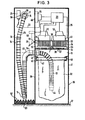
Nach der Zeichnung ist die erfindungsgemäße Schmutzsaugvorrichtung in einem quaderförmigen Blech- oder Kunststoffgehäuse 36 untergebracht, welches unten auf dem Boden 37 einer Selbstbedienungstankstelle steht. Die Vorderwand 38 des Gehäuses 36 besitzt in ihrem in Fig. 1 linken Bereich eine sich in der Höhe etwas über die Hälfte der Höhe des Gehäuses 36 erstreckende herausnehmbare rechteckige Klappe 39, deren Breite etwas größer als die Breite des Gehäuses 36 ist. Hinter der herausnehmbaren Klappe 39 ist gemäß den Fig. 1 bis 3 in etwa halber Höhe des Gehäuses 36 eine einerseits an der linken Seitenwand 41 in Fig. 1 und andererseits an einer vertikalen Zwischenwand 29 des Gehäuses 36 angebrachte Haltevorrichtung 40 für einen sackartig ausgebildeten Schmutzsammelbehälter 32 vorgesehen. In die Haltevorrichtung 40 greift ein den Schmutzsammelbehälter 32 oben haltender Spannrahmen 42 ein.According to the drawing, the dirt suction device according to the invention is accommodated in a cuboid sheet metal or
Wesentlich ist, daß der Schmutzsammelbehälter 32 oben großflächig weitgehend/offen ist, so daß die dort nach oben austretende Luftströmung nur eine geringe Vertikalgeschwindigkeit besitzt.It is important that the
Etwa in mittlerer Höhe der Zwischenwand 29 befindet sich in ihrem vorderen Bereich ein Wand-Durchlaßstutzen 43, an den zum Schmutzsammelbehälter 32 hin ein nach unten abgekrümmter Ansaugschlauch 13 anschließt, dessen Auslaßende 44 möglichst weit unten innerhalb des Schmutzsammelbehälters 32 mündet.Approximately in the middle of the
Oberhalb des Schmutzsammelbehälters 32 und des Stutzens 43 ist in nicht dargestellter Weise eine horizontal verlaufende ebene Prallplatte 31 befestigt, neben der ringsum breite Luftdurchlaßspalte 44 vorgesehen sind.Above the
In vertikalem Abstand oberhalb der Prallplatte 31 befindet sich eine quer zwischen der Zwischenwand 29 und der Seitenwand 41 verlaufende Querwand 30, welche das Gehäuse 36 in einen unteren Hauptansaugkasten 11 und in einen oberen Aufnahmeraum 35 für verschiedene Betätigungs- und Antriebselemente unterteilt. In die Querwand 30 sind nebeneinander zwei Hauptsaugturbinen 12 eingebaut, deren nicht dargestellte Saugöffnungen von Ringfilterpaketen 33 umgeben sind, die aus in der dargestellten Weise gefaltetem Filtermaterial bestehen. Oben liegen die Ringfilterpakete 33 von unten dicht an der Querwand 30 an und umgeben dort die nicht dargestellte Saugöffnung der Hauptsaugturbinen 12. Unten liegen die Ringfilterpakete 33 dicht an der Oberseite der Prallplatte 31 an. Die von den Hauptsaugturbinen 12 angesaugte Luft ist somit gezwungen, durch die breiten Ringspalte 44 hindurch auf die großflächige, mit Falten versehene Außenwand 34 des Ringfilterpaketes 34 aufzutreffen. Die gefilterte Luft wird dann von den Hauptsaugturbinen 12 in nicht dargestellter Weise nach außen geblasen.At a vertical distance above the
Der vorzugsweise auch als flexibler Schlauch ausgebildete Ansaugkanal 13 geht im Anschluß an den Durchführungsstutzen 43 und einen um 90° nach unten abgewinkelten Rohrkrümmer 45 in einen flexiblen Schlauch 14 über, der in dem in den Figuren dargestellten Zustand in Form einer Schleife 15 zunächst vom Rohrkrümmer 45 nach unten und dann schließlich nach oben bis zu einer in der Vorderwand des Gehäuses 36 vorgesehenen kreisförmigen Durchtritts-öffnung 17 geführt ist, wo er von innen nach außen durch die Vorderwand hindurchtritt, um dann in der aus Fig. 1 und 2 ersichtlichen Weise senkrecht nach unten herabzuhängen. Am äußeren Ende des flexiblen Schlauches 14 ist ein Saugstutzen 46 befestigt. In relativ geringen Längsabständen ist der flexible Schlauch rundum mit Umfangsrippen 24 versehen.The
In einem relativ geringen Abstand vom Saugstutzen 46 weist der flexible Schlauch 14 rundum einen Anschlagflansch 19 auf, der sich in Richtung der Schleife 15 noch in ein Schrumpfschlauchstück 46 fortsetzt, innerhalb dessen ein möglichst flach ausgebildeter Signalgeber 20 untergebracht ist, der z.B. als ein magnetisches oder metallenes Plättchen ausgebildet sein kann.At a relatively short distance from the
Das Material 47 um die öffnung 17 herum weist nach Fig. 2 in Axialrichtung eine gewisse Erstreckung auf, die größer sein sollte als der Längsabstand der Umfangsrippen 24.According to FIG. 2, the
Die Dimensionierung des Durchmessers der öffnung 17 ist so gewählt, daß zwischen den Umfangsrippen bzw. dem Schrumpfschlauch 46 und dem Rand 18 der Öffnung 17 noch ein geringfügiges Spiel verbleibt.The dimensioning of the diameter of the
Der in Fig. 7 linke Bereich des Gehäuses 36 bildet einen von oben nach unten durchgehenden, bis auf die Öffnung 17 allseits luftdicht abgeschlossenen Hilfssaugkasten 16, der durch eine in Fig. 2 oben rechts an die Zwischenwand 29 angeschlossene Hilfssaugturbine 25 unter Unterdruck gesetzt werden kann. Die Hilfssaugturbine 25 ist durch eine Bohrung 48 an den Hilfssaugkasten 16 angeschlossen.The area of the
Nach Fig. 3 befindet sich neben der Durchlaß-Öffnung 17 im Bereich des Signalgebers 20 ein Signalnehmer 21, der als auf ein Metallplättchen oder ein magnetisches Plättchen in der Nähe ansprechender Schalter, z.B. Reed-Schalter ausgebildet sein kann. Der Signalnehmer 21 ist über eine Leitung 22 mit einer Steuerschaltung 23 verbunden, die im Aufnahmeraum 35 oberhalb der Hauptsaugturbinen 12 untergebracht ist. Die Steuerschaltung 23 schaltet auch die Hauptsaugturbinen 12 und die Hilfssaugturbine 25.According to Fig. 3, in addition to the
In strichpunktierten Linien ist in Fig. 3 auch noch eine weitere Ausführungsform angedeutet, bei der die Hauptsaugturbinen 12 auch zur Erzeugung des Unterdruckes in dem Hilfssaugkasten 16 ausgenutzt werden, wodurch die Hilfssaugturbine 25 entbehrlich wird.A further embodiment is also indicated in dash-dotted lines in FIG. 3, in which the
Bei dieser Ausführungsform kann unterhalb der Prallplatte 31 ein Lochblech 27 angeordnet sein, welches sich über die gesamte horizontale Querschnittsfläche des Hauptsaugkastens 11 erstreckt. Darüber befindet sich ein Lochschieber 26, der in der dargestellten Lage einen Luftdurchgang von unten nach oben ermöglicht. Wird jedoch der Lochschieber 26 durch eine Betätigungsvorrichtung 49 in Richtung des Pfeiles f in Fig. 3 verschoben, so kommen die Löcher des Lochbleches 27 und des Lochschiebers 26 außer Ausrichtung, was zu einem luftdichten Verschluß zwischen dem Hilfssaugkasten 11 und dem Raum oberhalb des Lochschiebers 26 führt. Gleichzeitig wird von der Steuerschaltung 23 her eine weitere Betätigungsvorrichtung 50 erregt, die eine in der Zwischenwand 29 vorgesehene Klappe 28 öffnet und so eine Strömungsverbindung zwischen den Hauptsaugturbinen 12 und dem Hilfssaugkasten 16 herstellt. Die Steuerschaltung 23 steuert die Klappe 28 einerseits und den Lochschieber 26 andererseits derart, daß die Hauptsaugturbinen 12 entweder an dem Hauptsaugkasten 11 oder an den Hilfssaugkasten 16 angeschlossen sind.In this embodiment, a
Die Arbeitsweise der beschriebenen Schmutzsaugvorrichtung ist wie folgL:
- Wenn ein Benutzer sein Fahrzeug aussaugen will, so wirft er zunächst ein Geldstück in den
dafür vorgesehenen Schlitz 51 im oberen Teil der Vorderwand des Gehäuses 36 (Fig. 1) ein. Hierdurch wird dieSteuerschaltung 23 veranlaßt, dieHauptsaugturbinen 12 in Betrieb zu setzen. Nunmehr ergreift der Benutzerden flexiblen Schlauch 14 vorzugsweise im Bereich des Saugstutzens 46 und zieht den Schlauchaus dem Hilfssaugkasten 16 in der erforderlichen Länge heraus. Er kann jetzt in gewünschter Weise sein Fahrzeug bequem von Schmutz und Staub reinigen.
- If a user wants to vacuum his vehicle, he first throws a coin into the
slot 51 provided in the upper part of the front wall of the housing 36 (FIG. 1). This causes thecontrol circuit 23 to put themain suction turbines 12 into operation. The user now grips theflexible hose 14 preferably in the area of thesuction nozzle 46 and pulls the hose out of theauxiliary suction box 16 in the required length. He can now conveniently clean his vehicle of dirt and dust in the desired manner.
Sobald eine in der Steuerschaltung 23 vorgesehene Zeitschaltung den voreingestellten Saugzyklus beendet, schaltet die Steuerschaltung 23 die Hauptsaugturbinen 12 ab und gleichzeitig die Hilfssaugturbine 25 ein. Alternativ könnte der Lochschieber 26 in die Schließ- und die Klappe 28 in die Öffnungsstellung geschaltet werden, wobei dann die Hauptsaugturbinen 12 weiterlaufen würden.As soon as a timing circuit provided in the
Nunmehr ist der Schmutzsaugvorgang beendet, und der im Hilfssaugkasten 16 aufgebaute Unterdruck saugt den flexiblen Schlauch 14 selbsttätig durch die Durchtrittsöffnung 17 hindurch in das Innere des Hilfssaugkastens 16, wobei sich die Schleife 15 ausbildet. Jeder im Bereich der Durchtrittsöffnung 17 befindliche Bereich des flexiblen Schlauches 14 wird aufgrund der durch den Ringspalt hindurchtretenden beschleunigten Luft gereinigt. Dabei abgestreifter Staub fällt auf den Boden 52 des Hilfsaugkastens 16, von wo er von Zeit zu Zeit durch eine nicht dargestellte Klappe entfernt werden kann.The dirt suction process is now ended, and the negative pressure built up in the
Bevorzugt ist nach Fig. 3 ein mit tiefen Rillen versehener Schaumstoffkörper 53 am Boden 52 vorgesehen, wobei die Rillen so eng und tief sind, daß sich darin zwar vom Schlauch 14 abgestreifter Staub und Schmutz sammeln kann, der auf dem Boden 52 aufliegende Schlauch 14 aber nicht mit dem in den Rillen gesammelten Staub erneut in Berührung kommt, was ansonsten zu einer Wiederverschmutzung führen könnte. Auf diese Weise kann der flexible Schlauch 14 mit der unteren durchhängenden Schleife 15 auf dem Boden 52 zur Auflage kommen.3, a
Das Einsaugen des flexiblen Schlauches 14 geht solange vor sich, bis der Flansch 19 an der Vorderwand des Gehäuses zur Anlage kommt. Hierbei schaltet der Signalgeber 20 über den Signalgeber 21 und die Steuerschaltung 23 die Hilfssaugturbine 25 bzw. die Hauptsaugturbine 12 aus.The
Im Bereich der Ansaugöffnung 48 der Hilfsturbine 25 befindet sich ein nicht dargestellter Vorfilter. Der von der Hilfsturbine 25 erzeugte Druck liegt bei 140 mm WS.In the area of the
Bei dem Signalgeber 20 und Signalnehmer 21 kann es sich zweckmäßigerweise um einen induktiven Näherungsschalter handeln.The
Der die Eintrittsöffnung 17 umgebende Kand 18 ist zweckmäßlgerweise als Teflondüse ausgebildet.The
Der Schlauch 14 wird mit möglichst geringem Spiel durch die Durchtrittsöffnung 17 hindurchgeführt, wobei das Spiel jedoch ausreichend groß bemessen wird, damit der flexible Schlauch 14 beim Einsaugen oder Herausziehen nicht in der Öffnung 17 hängenbleibt.The
Um eine einwandfreie Schleifenbildung zu erzielen, soll die Austrittsöffnung 17 möglichst ganz oben in der Vorderwand des Gehäuses 36 vorgesehen sein, während der Ubergangsstutzen 43 für den Anschluß des Ansaugkanals 13 ganz vorne und möglichst hoch an der Zwischenwand 29 angeordnet ist. Am zweckmäßigsten mündet der Ansaugkanal 13 unmittelbar oberhalb der Haltevorrichtung 40 für den Schmutzsammelbehälter 32.Zwecks möglichst vollständigen Ausfahrens des flexiblen Schlauchs 14 kann der Rohrkrümmer 45 um die mit dem Anschlußstutzen 43 gemeinsame Horizontalachse 54 schwenkbar sein. Weiter ist es zweckmäßig, daß der Schlauch von seinem Eintritts- bis zu seinem Austrittsende nur eine einzige Schleife 15 im eingezogenen Zustand aufweist, wodurch ein zwangloses Einziehen gewährleistet wird.In order to achieve a perfect loop formation, the
Zweckmäßig wird die Hilfssaugturbine 25 nur durch die Schaltvorrichtung 20, 21 geschaltet, so daß sie bei herausgezogenem Schlauch stets läuft, d.h. auch bei eingeschalteten Hauptsaugturbinen 12. Dann kann sich die Auszugslänge stets automatisch dem Bedarf anpassen.The
Claims (9)
Applications Claiming Priority (2)
| Application Number | Priority Date | Filing Date | Title |
|---|---|---|---|
| DE19853526328 DE3526328A1 (en) | 1985-07-23 | 1985-07-23 | DIRT SUCTION DEVICE |
| DE3526328 | 1985-07-23 |
Publications (2)
| Publication Number | Publication Date |
|---|---|
| EP0209901A2 true EP0209901A2 (en) | 1987-01-28 |
| EP0209901A3 EP0209901A3 (en) | 1988-01-20 |
Family
ID=6276527
Family Applications (1)
| Application Number | Title | Priority Date | Filing Date |
|---|---|---|---|
| EP86110135A Ceased EP0209901A3 (en) | 1985-07-23 | 1986-07-23 | Dirt sucking apparatus |
Country Status (3)
| Country | Link |
|---|---|
| US (1) | US4688292A (en) |
| EP (1) | EP0209901A3 (en) |
| DE (1) | DE3526328A1 (en) |
Cited By (1)
| Publication number | Priority date | Publication date | Assignee | Title |
|---|---|---|---|---|
| US5651945A (en) * | 1994-07-30 | 1997-07-29 | Degussa Aktiengesellschaft | Carbon black reactor and method of producing carbon black |
Families Citing this family (24)
| Publication number | Priority date | Publication date | Assignee | Title |
|---|---|---|---|---|
| DE8634311U1 (en) * | 1986-12-22 | 1987-02-26 | Rowenta-Werke Gmbh, 6050 Offenbach, De | |
| DE8903472U1 (en) * | 1989-03-20 | 1989-05-03 | Sohler Airtex Gmbh, 7988 Wangen, De | |
| ES2041635T3 (en) * | 1990-01-24 | 1995-09-16 | Vaccar Systems Pty Ltd | A SERVICE STATION PLATFORM INSTALLATION. |
| CA2093715A1 (en) * | 1993-04-08 | 1994-10-09 | Garry Workhoven | Vacuum hose storage and access apparatus for a central vacuum cleaning system |
| US5740581A (en) * | 1996-06-21 | 1998-04-21 | Vacs America, Inc. | Freestanding central vacuum system |
| US6389641B1 (en) | 1998-06-15 | 2002-05-21 | Tennant Company | Dual mode debris pickup machine |
| US6092261A (en) * | 1998-06-17 | 2000-07-25 | Tennant Company | Storage system for vacuum pickup hose |
| US6044954A (en) * | 1998-06-19 | 2000-04-04 | Western Paytel, Inc. | Method and apparatus for selective operation of an air compressor and vacuum machine |
| US6058560A (en) * | 1998-08-04 | 2000-05-09 | Gab; Wayne Gerard | Vac-in-a-box |
| EP1031311A1 (en) * | 1999-02-16 | 2000-08-30 | Flexible Ducting Limited | Suction hose comprising rigid and flexible portions |
| US6427284B1 (en) | 2000-12-20 | 2002-08-06 | Vacs America, Inc. | Central vacuum hose storage |
| US6560816B1 (en) * | 2001-01-31 | 2003-05-13 | Vacs America, Inc. | Central vacuum system with bag mounting assembly |
| US7010829B2 (en) * | 2003-06-05 | 2006-03-14 | James Roger Harman | Retractable hose central vacuum cleaning system apparatus and method |
| GB2409403B (en) * | 2003-12-23 | 2006-12-27 | Techtronic Ind Co Ltd | Suction cleaners |
| US7363679B2 (en) * | 2005-07-22 | 2008-04-29 | Whirlpool Corporation | Vacuum system |
| US20070017057A1 (en) * | 2005-07-22 | 2007-01-25 | Zimmerle Johnny W | Convertible vacuum system |
| DE102006006009A1 (en) * | 2006-02-08 | 2007-08-09 | Degussa Gmbh | Method for measuring the uniform filling of reactors with solids |
| US20090188073A1 (en) * | 2008-01-29 | 2009-07-30 | H-P Products, Inc. | Vacuum hose storage system |
| US8590098B2 (en) * | 2008-01-29 | 2013-11-26 | H-P Products, Inc. | Vacuum hose storage system |
| US7945990B2 (en) * | 2008-01-29 | 2011-05-24 | H-P Products, Inc. | Vacuum hose storage system |
| US8479353B2 (en) * | 2008-07-23 | 2013-07-09 | Rod Drivstuen | Hose valve apparatus and method for retractable hose vaccum systems |
| BE1022169B1 (en) * | 2014-11-28 | 2016-02-24 | Ergox Bvba | CENTRAL DUST VACUUM SYSTEM AND ITS USE |
| US10292558B2 (en) * | 2015-02-25 | 2019-05-21 | M.D. Manufacturing, Inc. | Vacuum hose retraction system |
| US11751735B2 (en) * | 2020-06-01 | 2023-09-12 | M.D. Manufacturing, Inc. | Vacuum and hose retraction system |
Citations (3)
| Publication number | Priority date | Publication date | Assignee | Title |
|---|---|---|---|---|
| US2051728A (en) * | 1935-01-11 | 1936-08-18 | Richard H Manning | Vacuum cleaner |
| FR1236062A (en) * | 1959-06-03 | 1960-07-15 | Device for purifying a body loaded with foreign particles | |
| DE2419681A1 (en) * | 1973-04-28 | 1974-11-21 | Hukuba Future Research Nagarey | VACUUM CLEANER |
Family Cites Families (6)
| Publication number | Priority date | Publication date | Assignee | Title |
|---|---|---|---|---|
| US1896128A (en) * | 1931-06-08 | 1933-02-07 | Ralph C Thompson | Clothes brushing and cleaning appliance |
| US2023955A (en) * | 1933-05-09 | 1935-12-10 | Laval A Cowen | Vending machine |
| US3977037A (en) * | 1973-10-15 | 1976-08-31 | Sanyo Electric Co., Ltd. | Vacuum cleaner |
| JPS50150277A (en) * | 1974-05-25 | 1975-12-02 | ||
| GB1472384A (en) * | 1975-01-24 | 1977-05-04 | Wright G | Vacuum cleaners |
| US4246675A (en) * | 1979-07-27 | 1981-01-27 | Costanzo Dean V | Industrial vacuum apparatus |
-
1985
- 1985-07-23 DE DE19853526328 patent/DE3526328A1/en active Granted
-
1986
- 1986-07-21 US US06/887,313 patent/US4688292A/en not_active Expired - Fee Related
- 1986-07-23 EP EP86110135A patent/EP0209901A3/en not_active Ceased
Patent Citations (3)
| Publication number | Priority date | Publication date | Assignee | Title |
|---|---|---|---|---|
| US2051728A (en) * | 1935-01-11 | 1936-08-18 | Richard H Manning | Vacuum cleaner |
| FR1236062A (en) * | 1959-06-03 | 1960-07-15 | Device for purifying a body loaded with foreign particles | |
| DE2419681A1 (en) * | 1973-04-28 | 1974-11-21 | Hukuba Future Research Nagarey | VACUUM CLEANER |
Cited By (1)
| Publication number | Priority date | Publication date | Assignee | Title |
|---|---|---|---|---|
| US5651945A (en) * | 1994-07-30 | 1997-07-29 | Degussa Aktiengesellschaft | Carbon black reactor and method of producing carbon black |
Also Published As
| Publication number | Publication date |
|---|---|
| DE3526328C2 (en) | 1987-11-26 |
| EP0209901A3 (en) | 1988-01-20 |
| DE3526328A1 (en) | 1987-02-05 |
| US4688292A (en) | 1987-08-25 |
Similar Documents
| Publication | Publication Date | Title |
|---|---|---|
| DE3526328C2 (en) | ||
| DE4204789C2 (en) | Device for removing dust from a dust air extracted on a workpiece processing machine | |
| DE60107089T2 (en) | Dust particle collector for cyclone separators | |
| DE60201019T2 (en) | VACUUM CLEANER | |
| DE3836748A1 (en) | BLOW / SUCTION DEVICE | |
| DE3135898A1 (en) | "METHOD AND DEVICE FOR COATING OBJECTS" | |
| DE3220644A1 (en) | EXTRACTION DEVICE | |
| DE69910232T2 (en) | VACUUM CLEANER | |
| DE633633C (en) | Vacuum cleaner mouthpiece | |
| DE3725204A1 (en) | WET SUCTION | |
| EP3681360B1 (en) | Surface cleaning appliance | |
| DE2101659A1 (en) | Automatic Bodenremigungsgerat, especially vacuum cleaner | |
| DE3815320C2 (en) | vacuum cleaner | |
| EP1407703A2 (en) | Air duct arrangement in suction cleaner head | |
| DE1252870C2 (en) | DRIVING CLEANING DEVICE FOR THE REMOVAL OF THE GASER FLIGHT, etc. OF MACHINE PARTS AND THE FLOOR IN TEXTILE MACHINE SHELVES | |
| EP0557978A1 (en) | Suction cleaning device | |
| DE2424179C3 (en) | Device for separating air and dust | |
| DE2343971A1 (en) | FLOOR CARE DEVICE | |
| DE595686C (en) | vacuum cleaner | |
| DE602004012047T2 (en) | Waste separation device for vacuum cleaners | |
| DE19508403A1 (en) | Device for removing liquid or liquid particles from an air flow | |
| DE3436064C2 (en) | Wet-dry vacuum cleaner | |
| DE1710436B2 (en) | MOBILE CLEANING DEVICE FOR TEXTILE MACHINERY | |
| EP0956806B1 (en) | Suction device for sucking in dirt or suction material containing dirt | |
| DE2902461A1 (en) | DEVICE FOR PURIFYING GAS |
Legal Events
| Date | Code | Title | Description |
|---|---|---|---|
| PUAI | Public reference made under article 153(3) epc to a published international application that has entered the european phase |
Free format text: ORIGINAL CODE: 0009012 |
|
| AK | Designated contracting states |
Kind code of ref document: A2 Designated state(s): AT BE CH DE FR GB IT LI LU NL SE |
|
| PUAL | Search report despatched |
Free format text: ORIGINAL CODE: 0009013 |
|
| AK | Designated contracting states |
Kind code of ref document: A3 Designated state(s): AT BE CH DE FR GB IT LI LU NL SE |
|
| 17P | Request for examination filed |
Effective date: 19880714 |
|
| 17Q | First examination report despatched |
Effective date: 19890823 |
|
| STAA | Information on the status of an ep patent application or granted ep patent |
Free format text: STATUS: THE APPLICATION HAS BEEN REFUSED |
|
| 18R | Application refused |
Effective date: 19900513 |