EP0209374A2 - Système de codage de phase en RMN utilisant des impulsions radiofréquence à phase variable - Google Patents
Système de codage de phase en RMN utilisant des impulsions radiofréquence à phase variable Download PDFInfo
- Publication number
- EP0209374A2 EP0209374A2 EP86305474A EP86305474A EP0209374A2 EP 0209374 A2 EP0209374 A2 EP 0209374A2 EP 86305474 A EP86305474 A EP 86305474A EP 86305474 A EP86305474 A EP 86305474A EP 0209374 A2 EP0209374 A2 EP 0209374A2
- Authority
- EP
- European Patent Office
- Prior art keywords
- phase
- pulse
- frequencies
- frequency
- range
- Prior art date
- Legal status (The legal status is an assumption and is not a legal conclusion. Google has not performed a legal analysis and makes no representation as to the accuracy of the status listed.)
- Granted
Links
Images
Classifications
-
- G—PHYSICS
- G01—MEASURING; TESTING
- G01R—MEASURING ELECTRIC VARIABLES; MEASURING MAGNETIC VARIABLES
- G01R33/00—Arrangements or instruments for measuring magnetic variables
- G01R33/20—Arrangements or instruments for measuring magnetic variables involving magnetic resonance
- G01R33/44—Arrangements or instruments for measuring magnetic variables involving magnetic resonance using nuclear magnetic resonance [NMR]
- G01R33/446—Multifrequency selective RF pulses, e.g. multinuclear acquisition mode
-
- G—PHYSICS
- G01—MEASURING; TESTING
- G01R—MEASURING ELECTRIC VARIABLES; MEASURING MAGNETIC VARIABLES
- G01R33/00—Arrangements or instruments for measuring magnetic variables
- G01R33/20—Arrangements or instruments for measuring magnetic variables involving magnetic resonance
- G01R33/44—Arrangements or instruments for measuring magnetic variables involving magnetic resonance using nuclear magnetic resonance [NMR]
- G01R33/48—NMR imaging systems
- G01R33/4818—MR characterised by data acquisition along a specific k-space trajectory or by the temporal order of k-space coverage, e.g. centric or segmented coverage of k-space
- G01R33/482—MR characterised by data acquisition along a specific k-space trajectory or by the temporal order of k-space coverage, e.g. centric or segmented coverage of k-space using a Cartesian trajectory
-
- G—PHYSICS
- G01—MEASURING; TESTING
- G01R—MEASURING ELECTRIC VARIABLES; MEASURING MAGNETIC VARIABLES
- G01R33/00—Arrangements or instruments for measuring magnetic variables
- G01R33/20—Arrangements or instruments for measuring magnetic variables involving magnetic resonance
- G01R33/44—Arrangements or instruments for measuring magnetic variables involving magnetic resonance using nuclear magnetic resonance [NMR]
- G01R33/48—NMR imaging systems
- G01R33/54—Signal processing systems, e.g. using pulse sequences ; Generation or control of pulse sequences; Operator console
- G01R33/56—Image enhancement or correction, e.g. subtraction or averaging techniques, e.g. improvement of signal-to-noise ratio and resolution
- G01R33/5604—Microscopy; Zooming
Definitions
- This invention relates to techniques for obtaining nuclear magnetic resonance (NMR) information from an object. More specifically, it relates to techniques for encoding information into the phase of a received NMR signal.
- NMR nuclear magnetic resonance
- NMR information about an object is ordinarily obtained by receiving a single time-varying radio frequency (rf) signal.
- this time-varying rf signal must provide the necessary information about the object being imaged, such as a human body. Therefore, the characteristics of this time-varying signal must somehow be modulated by the atomic nuclei in the object to provide information about those nuclei.
- the distribution of nuclei of a particular element is typically encoded into the phase and amplitude of the received time-varying signal.
- Various techniques have been developed for enabling the nuclei to encode information into the received signal.
- phase encoding in NMR imaging is to encode information about the spatial location of atomic nuclei having a particular resonance.
- nuclei are initially excited into a resonant state from which they decay according to an appropriate time constant. While in the excited state, the nuclei may be phase encoded by the application of a relatively low frequency pulsed magnetic field gradient.
- the effect of the low frequency gradient is to change the phase of the decay, but because the gradient varies across a spatial dimension, the amount of phase change varies according to the position of the nuclei, so that the resulting phases of the nuclei provide the desired spatial information.
- phase encodes spectroscopic information by changing the timing of one or more refocusing pulses in a pulse and gradient switching sequence which produces a series of spin echoes.
- the sequence also includes the application of an observation gradient during the echoing NMR signals, so that the refocusing of the nuclear spins is determined by the combination of the refocusing pulse and the observation gradient.
- a mismatch of the timing of these signals results in a phase change of the received NMR signal which evolves during the observation gradient and which depends on the frequency difference between the spin resonance of the nucleus and the reference frequency absent applied field gradients.
- This technique makes it possible to separate two chemically shifted systems such as lipids and water having the same resonant nucleus, in this case protons, but different resonant frequencies, and successive applications of the mistimed refocusing pulses make it possible to obtain more detailed spectral discrimination.
- Amplitude encoding suffers a loss of sensitivity compared with phase encoding, so that phase encoding is often preferable.
- phase encoding depend heavily upon the application of pulsed magnetic gradient fields. These gradient fields are typically applied by gradient coils which have a number of problems, including audio frequency vibrations, high power supply requirements, and heavy duty switching requirements. It would be advantageous to provide phase encoding techniques which could be used without gradient fields. More generally, it would be advantageous to provide phase encoding techniques which would produce a continuous phase variation across the entire range of resonant frequencies using an rf pulse, providing greater flexibility than has previously been available.
- a method of retrieving phase-encoded NMR information from an object, characterised by phase encoding nuclei in the object to provide a phase-encoded NMR signal the step of phase encoding comprising applying an rf pulse with a substantially continuous frequency range covering a range of resonant frequencies of the nuclei, and producing a substantially continuous phase variation across the range of resonant frequencies; and receiving the phase-encoded NMR signal.
- the invention generally provides techniques for phase encoding in which an rf pulse produces a generally continuous phase variation across the range of resonant frequencies of the atomic nuclei which provide an NMR signal.
- One aspect of the invention provides techniques for phase encoding which make it possible to perform phase encoding without applying low frequency pulsed magnetic gradient fields. The invention thus makes it possible to perform phase encoding on conventional high resolution spectrometers without adding gradient coils of the type described above.
- the invention further provides phase encoding techniques which can be used on conventional NMR imaging systems with gradient coils to provide added versatility.
- the present invention is based on the discovery that phase encoding of NMR information may be performed using sequences of rf pulses which produces a substantially continuous phase variation across the resonant frequency range of the atoms of an object.
- One embodiment of the invention is based on the further discovery that tailored rf pulses with either phase or amplitude spectra which vary with frequency may be used in the phase encoding of NMR information in a received signal.
- Another aspect of the present invention is based on the discovery that rf pulses which bring the atomic nuclei into the excited state may also be used in phase encoding.
- rf field gradients produced by inhomogeneous rf coils may be used in a sequence to perform phase encoding during excitation without the application of pulsed magnetic gradient fields.
- the rf pulse used in phase encoding may be a tailored pulse with either its magnitude or its phase varying linearly with frequency across a continuous range.
- the rf pulse may be generated by defining its magnitude and phase spectra, transforming them to obtain time-varying real and imaginary components, and applying the rf pulse modulated by the real and imaginary components.
- the rf pulse may be applied through an inhomogeneous coil to produce an rf gradient field across the object, and the gradient field may have a null point within the object.
- a tailored rf pulse with a linearly varying magnitude is applied through the inhomogeneous coil.
- Fig. 1 sets forth in flow diagram form the fundamental functions performed during NMR information retrieval.
- excitation waveforms are applied to an object in order to bring at least some of the atomic nuclei of the object into an excited state.
- the excitation waveforms are typically applied in the presence of a static magnetic field which establishes a reference resonant frequency f O , around which the resonance frequencies of the nuclei vary across a range due to chemical shift and field inhomogeneity, but may also include pulsed magnetic gradient fields which cause the resonance frequencies to vary across a range due to location.
- the excitation waveforms include appropriate rf pulses for exciting at least some of the atomic nuclei in the object into an excited state from which they will precess to provide an NMR signal. This may be done by tipping all of the spin magnetization axes of the atoms of an object into a focused position from which they precess, resulting in a decaying NMR signal.
- additional waveforms may be applied to cause the spin magnetizations to refocus in order to obtain additional echoing NMR signals.
- encoding waveforms are applied to the object in order to encode information into the NMR signals. This may be done by encoding the spin magnetizations of the excited atomic nuclei with information relating to their spatial location, the chemical shift of their resonant frequency from f O or the inhomogeneity of the static field.
- Fig. 1 shows the encoding in box 20 occurring after the excitation in box 10, this is only illustrative, and one aspect of the present invention makes it possible for phase encoding to occur during an rf excitation pulse sequence.
- each nuceus may be thought of as a spin system which is resonant at a frequency which depends on its makeup and on the local magnetic field. Therefore, each spin system, in effect, will only receive those input waveforms which are received at its resonant frequency. The phase and amplitude of the waveforms at that frequency will determine the subsequent response of that spin system. Therefore, the waveforms applied in boxes 10 and 20 may include waveforms which establish the local magnetic field in addition to the waveforms which perform excitation and encoding of information about the spin system.
- an NMR response waveform is generated.
- This waveform occurs as the spin systems of the atomic nuclei in the object precess and decay from their excited state.
- the decay processes provide a waveform which may be received by an rf coil, detected with reference to a reference frequency, sampled, and stored in a data set for subsequent processing. If both amplitude and phase information are obtained, it may be possible to perform Fourier imaging by transforming the data set to obtain an image. Other techniques such as projection reconstruction may also be used to obtain an image from the data set. Even if the received NMR signal waveform does not include spatial information, it may be used to obtain spectroscopic information about an object. In any event, the usefulness of the output waveform in box 30 depends on whether useful information has been encoded into the spin systems of the atomic nuclei in box 20.
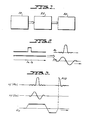
- Figs. 2 and 3 illustrate an example of how input waveforms may be applied to an object. More specific thoughally, Figs. 2 and 3 illustrate how a tailored excitation, a specific types of input waveform which is used in some embodiments of the present invention, may be used in NMR imaging to select a specific part of an object to be imaged such as a slice.
- Fig. 2 shows how the tailored excitation for slice selection may be defined and generated.
- the spectral graph includes a magnitude spectrum and a phase spectrum, both of which cover a range of frequencies.
- the frequencies of interest in Fig. 2 are a narrow band of frequencies between a lower bound f a and an upper bound f b .
- the magnitude spectrum has a constant value, so that for each of the frequencies between f a and f b , the magnitude of the signal will be the same.
- the phase will be zero at all frequencies so that the phase spectrum is entirely flat.
- the magnitude and phase spectra may be transformed into the real and imaginary components shown at the right in Fig. 2. These components may be applied to the object in the manner described in P. Mansfield, A. A. Maudsley, T. Baines, "Fast Scan Proton Density Imaging by NMR", Journal of Physics E: Scientific Instruments, Vol. 9 (1976), pp. 271-278, at pp. 272-273 and Fig. 4.
- a tailored excitation pulse will be applied to the atomic nuclei of the object whose magnitude and phase spectra are those shown at the left in Fig. 2.
- Fig. 3 shows how the tailored rf pulse of Fig. 2 may be applied as a selective excitation pulse which excites only the atoms of a slice of the object.
- the object will be subject to a static magnetic field oriented along the Z axis, and the application of a pulsed field gradient G z varying in the Z direction as shown in Fig. 3 will bias the atomic nuclei of the ob jects so that the slice of nuclei at each value of z along the Z axis will have a corresponding resonant frequency f z . Therefore, when the real and imaginary components of the tailored pulse shown in Fig.
- G z may then be reversed, which will result in a free induction decay (FID) signal at the time when the integral of the amplitude of the negative portion of G z is equal to one-half the integral of the amplitude of the positive portion, assuming that the tailored rf pulse was applied at the center of the positive portion of the G z gradient.
- FID free induction decay
- Figs. 2 and 3 illustrate that tailored pulses have been used as selective excitation pulses, and further variations on selective pulses are described in A. A. Maudsley, “Multiple-Line-Scanning Spin Density Imaging", Journal of Magnetic Resonance, Vol. 41 (1980) pp. 112-126 at 119-121. These prior techniques, however, did not recognize the possibility that a tailored rf pulse could be used in a sequence for phase encoding of NMR information, as in the present invention.
- tailored rf pulses and other rf pulses may be applied in sequence for phase encoding NMR information about an object by producing a substantially continuous phase variation across the range of resonant frequencies of a set of atomic nuclei.
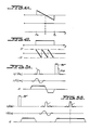
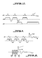
- Figs. 4A and 4B are spectral diagrams showing two examples of tailored rf pulses which may be used in sequences for phase encoding of information according to the invention. These spectral diagrams are based on the discovery that a tailored rf pulse having frequencies in a bounded continuous range can be used to provide phase encoding if either the phase or magnitude is constant across that range and the other spectrum, either magnitude or phase, varies linearly across the continuous range, which covers the range of resonant frequencies of the relevant atomic nuclei.
- Fig. 4A shows the amplitude or magnitude variant tailored rf pulse for use in a sequence according to the present invention.
- the amplitude variant pulse includes frequencies across a continuous range from the lower frequency f a to the upper frequency f b .
- the central frequency has zero magnitude, but the spectrum could have all positive or all negative magnitudes, provided the magnitude varies linearly across the continuous range.
- the phase is constant across the continuous range.
- Fig. 4B shows a phase variant tailored rf pulse which also includes frequencies across the continuous range between f a and f b . For all of those frequencies, the magnitude is the same, and for frequencies outside that range, the magnitude is zero, as in Fig. 4A. The phse, however, varies linearly across the range between f a and f b . The phase could vary over a wider or narrower range of values than shown in Fig. 4B. As in Fig. 4A, however, the atomic nuclei of the object will be phase shifted depending on the resonant frequency of the nuclei.
- each of the spectra shown in Figs. 4A and 4B may be transformed to provide real and imaginary components, which may then be used to modulate an rf pulse applied as shown in Figs. 5A and 5B.
- Fig. 5A illustrates a simple example by which a 90° excitation pulse after a tailored rf pulse having spectra like those shown in Fig. 4A results in an FID signal in which spatial information is phase encoded due to the tailored rf pulse applied during gradient G and followed by a 90° excitation pulse. This technique is discussed below in relation to Fig. 7.
- Fig. 5B illustrates an example in which a tailored 180° refocusing pulse having spectra like those shown in Fig. 4B results in an echo signal in which spectroscopic information is phase encoded.
- a preobservation gradient G is applied before the refocusing pulse so that the echo signal will occur at the center of a subsequent observation pulse G. If this echo signal is sampled, and the samples are stored in a data set which is subsequently transformed, spectroscopic information about the object can be obtained from the phase of the sampled signal.
- Fig. 5B Although the pulse sequence of Fig. 5B is used for spectroscopic encoding, it could be used for spatial encoding by applying a pulsed magnetic field gradient during the tailored refocusing pulse. This gradient, however, must be orthogonal to the gradient G used for observation.
- rf pulses make it possible to perform continuous phase encoding without gradient fields, although rf pulses such as the tailored pulses described above may also be used with pulsed magnetic gradient fields, providing a wide variety of possible imaging techniques.
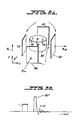
- Fig. 6A shows an rf coil configuration which can be used to apply an rf gradient field.
- Fig. 6B is a timing diagram of a pulse sequence applied through the coil configuration of Fig. 6A.
- Fig. 7 illustrates how the rf gradient field will affect volume elements of an object being imaged. Similar techniques are disclosed in co-assigned U.S. application Serial No. 756 066 (filed on 17 July 1985), incorporated herein by reference.
- the coil arrangement shown schematically in Fig. 6A includes two rf coils, coil A and coil B.
- Coil A is a saddle-type coil including two halves 40 and 50 which produce a homogeneous magentic rf field in the Y direction as shown in Fig. 6A.
- Coil B includes two halves 60 and 70 which produce an inhomogeneous magnetic field which could, for example, be a linear gradient along the X direction.
- Coil B may simply be a standard rf coil like coil A, but rewired so that it produces zero field at the center point between the coil halves 60 and 70.
- the object 80 to be imaged is shown between the coils in Fig. 6A, and it includes three small volume elements of spin magnetized nuclei, A, B, and C.
- Fig. 6B shows a simple pulse sequence using the coils of Fig. 6A to produce phase encoding.
- An inhomogeneous encoding pulse is first applied having a broad band of frequencies. Then a homogeneous 90° excitation pulse is applied, resulting in a FID signal.
- the phase encoding pulse of the FID signal is complete only when both of these pulses have been applied, even though we refer to the first pulse as an encoding pulse.
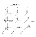
- Fig. 7 illustrates how the rf pulse sequence of Fig. 6 will affect the spin magnetization in each of the volume elements A, B, and C.
- the tailored encoding pulse is 90° ahead of the excitation pulse in phase.
- the three volume elements are shown oriented along the Z' axis, the position which they would take as a result of the static magnetic field on the Z' axis.
- an rf pulse applied through coil B changes the orientation of the spin in some of the volume elements.
- this pulse is applied along the X' axis, which is arbitrarily assigned to have a phase of zero.
- the spin axis of volume element A is rotated toward the positive Y' axis, while the spin axis of volume element C is rotated in the opposite direction toward the negative Y' axis.
- the spin axis of volume element B is unaffected, however, because, as noted above, a zero rf field is produced at the center point between coil halves 60 and 70. As can be seen from Fig. 7, this will result in a spatial variation of the spin axis orientations of the volume elements, since the orientation of the spin axis in each volume element will now be distinct from that of volume elements at other points along the X' axis.
- a 90° excitation pulse is applied through coil A, as shown in the third line of Fig. 7.
- This pulse is applied along the Y' axis, at a phase of 90° relative to the X' axis, so that it tips all of the spin axes out of the Y'-Z' plane into the X'-Y' plane.
- the spins will be tipped into the X'-Y' plane with different phase, however, effectively completing the phase encoding.
- the excited nuclei will decay, producing a FID signal, as discussed above in relation to Fig. 5A.
- This FID may be detected by a receiver coil, and coil A of Fig. 6A is a suitable receiver coil.
- Figs. 8-10 illustrate more complicated sequences making use of the basic phase encoding techniques discussed above.
- Fig. 8 shows a sequence in which broadband encoding pulses are applied through inhomgeneous rf coils.
- Fig. 9 shows a sequence in which linearly varying tailored rf pulses are applied through homogeneous rf coils in the presence of pulsed magnetic field gradients.
- Fig. 10 shows a sequence in which a slice selective tailored rf pulse is applied through an inhomogeneous rf coil in the presence of a gradient field. Therefore, the sequences of Figs. 8 and 9 may be used in three-dimensional imaging while the sequence of Fig. 10 may be used in two-dimensional imaging.
- the pulse sequence of Fig. 8 makes use of three inhomogeneous rf coils like coil B in Fig. 6A to perform three dimensional spectroscopic imaging without pulsed magentic gradient fields. Instead, a broadband rf encoding pulse is applied through each of the three inhomogeneous coils to provide a variation in amplitude in each of the three spatial dimensions.
- the pulses are shown in sequence, but they could all be applied at once. These pulses are preferably all applied along the X' axis in the rotating frame, i.e., with phase equal to zero, as indicated in Fig.
- an FID signal will occur containing three-dimensional spatial information as well as spectroscopic information.
- This signal may be sampled and stored in a data set.
- the sequence of Fig. 8 requires that the broadband rf encoding pulses be applied at a number of amplitudes, the time required for making the necessary measurements and for the subsequent data processing is larger than for most forms of NMR imaging.
- the sequence of Fig. 8 may be advantageous, however, for the observation of sodium relaxation and chemical shift information. In this application, it is desirable to observe contributions resulting from short T2 decay times, and this is made possible by the direct observation of the FID, which would not be possible with the more common spin echo technique commonly used for Fourier imaging.
- the short T1 decay time for sodium permits a short repetition period between successive measurements, making the acquisition of a large number of measurements less burdensome.
- the T2 time is relatively short, so that relaxation effects occurring during the rf phase encoding pulses prior to observation must be taken into account in the subsequent processing.
- Fig. 9 shows a pulse and gradient switching sequence very similar to that of Fig. 8, but in which tailored amplitude varient pulses are applied during respective pulsed magnetic field gradients G x , G y and G z .
- the amplitude variant pulses may be ap plied with a single rf coil producing a homogeneous field distribution.
- the three amplitude variant pulses are applied with the same phase, so that they are all applied along the X' axis.
- the subsequent 90° excitation pulse is applied along the Y' axis, 90° out of phase with the amplitude variant pulses, so that it flips the spins into the X'-Y' plane, as in Fig. 7.
- the phase encoding can be incremented for successive measurements by changing the gain used for each of the amplitude variant pulses, by changing the gradient strength for each of the pulsed magnetic gradient fields, or by changing the phase change per unit of frequency in the magnitude spectrum of the amplitude variant pulses.
- the resulting FID may be sampled and stored in a data set, and this pulse and gradient switching sequence may also be appropriate for sodium chemical shift observation, but once again the relaxation effects during the phase encoding must be taken into account.
- Fig. 10 shows another application of the amplitude variant pulse of the present invention, this time to perform multiple-plane two-dimensional imaging, also rereferred to as two-dimensional multislice imaging.
- a tailored amplitude variant pulse and a subsequent tailored 90° excitation pulse are applied to select a limited region of the object in order to obtain a two-dimensional image rather than a three-dimensional image, and this is accomplished by applying these pulses in the presence of a slice selective gradient along the G z axis.
- the amplitude variant pulse is applied through coil B, producing an rf field gradient affecting the atomic nuclei in the slice.
- the homogeneous 90° excitation pulse is applied through coil A to tip the spin axes in the slice into the X'-Y' plane.
- a preobservation pulse of gradient G y is applied, after which a 180° refocusing pulse is applied through coil A along the X' axis, re sulting in a spin echo observed during a subsequent observation gradient pulse in G y .
- a complete data set may be obtained by varying the gain used for the amplitude variant pulse, the selective gradient pulse strength, or the phase change per unit frequency of the amplitude variant pulse.
- this pulse and gradient switching sequence may be varied for three-dimensional imaging or to produce additional spin echo signals at later time periods.
- phase encoding techniques according to the invention may also be used in conjunction with surface coil techniques, and, as discussed above, may be used in commercial high-resolution spectrometer systems for imaging without providing a full set of field gradient coils and power supplies.
- the tailored phase variant pulses with spectra as in Fig. 4B are not used in any of the sequences in Figs. 8-10, but may also be used for specific examples of phase encoding. Because a phase variant pulse along one spatial axis cannot be spatially selective along an orthogonal axis, the phase variant pulse is not well suited for multislice imaging. It may, however, be useful in volume imaging and for single plane spectroscopic imaging in which a time delayed selective refocusing pulse is used to enable slice selection along with phase encoding of spectroscopic information.
- the sequence of Fig. 5B uses a tailored non-selective phase variant 180° refocusing pulse, but could be modified for slice selection.
- a phase variant 90° excitation pulse may also be applied to perform phase encoding of spectroscopic information, with slice selection or additional spatial encoding being performed later.
- the rf pulses may be used in a wide variety of sequences for phase encoding spatial and spectroscopic information. If a tailored rf pulse is used, the resolution in each of the encoding dimensions may be software programmable in that the magnitude or phase which varies across the frequency range of the pulse can be changed at will. In conventional Fourier imaging using pulsed magnetic field gradients, the spatial resolution in the encoding dimension depends directly on the number of independent phase encoding measurements made, and this resolution is constant across that dimension, so that it is not possible to image a limited region with increased resolution. With the tailored rf pulses, however, it is possible to program the phase encoding increment per point to be greater over a selected region, making it possible to obtain an image with varying spatial resolution, providing a sort of "zoom" capability.
- the above description relates to the phase encoding of spatial and spectroscopic information.
- the rf pulses may, however, be used for encoding other types of information, such as information discriminating flow of velocities of fluids in an object. This might be done by measuring differences following the application of spatially dependent excitation and refocusing pulses.
Priority Applications (1)
| Application Number | Priority Date | Filing Date | Title |
|---|---|---|---|
| AT86305474T ATE67607T1 (de) | 1985-07-17 | 1986-07-16 | Phasenkodierung bei der magnetischen kernresonanz mit in der phase varierenden hochfrequenzimpulsen. |
Applications Claiming Priority (2)
| Application Number | Priority Date | Filing Date | Title |
|---|---|---|---|
| US756035 | 1985-07-17 | ||
| US06/756,035 US4689566A (en) | 1985-07-17 | 1985-07-17 | NMR phase encoding using phase varying rf pulses |
Publications (3)
| Publication Number | Publication Date |
|---|---|
| EP0209374A2 true EP0209374A2 (fr) | 1987-01-21 |
| EP0209374A3 EP0209374A3 (en) | 1988-01-07 |
| EP0209374B1 EP0209374B1 (fr) | 1991-09-18 |
Family
ID=25041760
Family Applications (1)
| Application Number | Title | Priority Date | Filing Date |
|---|---|---|---|
| EP86305474A Expired - Lifetime EP0209374B1 (fr) | 1985-07-17 | 1986-07-16 | Système de codage de phase en RMN utilisant des impulsions radiofréquence à phase variable |
Country Status (5)
| Country | Link |
|---|---|
| US (1) | US4689566A (fr) |
| EP (1) | EP0209374B1 (fr) |
| JP (1) | JPS6297544A (fr) |
| AT (1) | ATE67607T1 (fr) |
| DE (1) | DE3681522D1 (fr) |
Cited By (6)
| Publication number | Priority date | Publication date | Assignee | Title |
|---|---|---|---|---|
| EP0284285A2 (fr) * | 1987-03-23 | 1988-09-28 | Varian Associates, Inc. | Zeugmatographie en repère tournant |
| WO1991015754A1 (fr) * | 1990-04-04 | 1991-10-17 | Timothy Paul Leslie Roberts | Experimentation et appareil de resonnance magnetique |
| WO1992002828A1 (fr) * | 1990-08-02 | 1992-02-20 | British Technology Group Ltd | Ameliorations concernant la spectroscopie et l'imagerie par resonance magnetique |
| WO1995009368A1 (fr) * | 1993-09-27 | 1995-04-06 | British Technology Group Limited | Appareil et procede d'essai par resonance nucleaire |
| US6091240A (en) * | 1994-09-29 | 2000-07-18 | Btg International Limited | Method of nuclear quadrupole resonance testing and method of configuring apparatus for nuclear quadrupole resonance testing |
| DE102007044463A1 (de) * | 2007-09-18 | 2009-04-02 | Bruker Biospin Mri Gmbh | Verfahren zur Bestimmung der räumlichen Verteilung von Magnetresonanzsignalen durch mehrdimensionale HF-Anregungspulse |
Families Citing this family (10)
| Publication number | Priority date | Publication date | Assignee | Title |
|---|---|---|---|---|
| US5212448A (en) * | 1991-08-09 | 1993-05-18 | General Electric Company | Nmr pulse sequence with burst rf excitation pulses having separately controlled phase |
| US5412322A (en) * | 1993-06-24 | 1995-05-02 | Wollin Ventures, Inc. | Apparatus and method for spatially ordered phase encoding and for determining complex permittivity in magnetic resonance by using superimposed time-varying electric fields |
| US7518362B2 (en) * | 2003-06-30 | 2009-04-14 | Hitachi Medical Corporation | Magnetic resonance apparatus utilizing time-varying rate of magnetic resonant frequency |
| US7511495B2 (en) * | 2005-04-25 | 2009-03-31 | University Of Utah | Systems and methods for image reconstruction of sensitivity encoded MRI data |
| JP2010508054A (ja) * | 2006-10-31 | 2010-03-18 | コーニンクレッカ フィリップス エレクトロニクス エヌ ヴィ | 複数の送信コイルを使用したmrirf符号化 |
| US8064982B2 (en) * | 2006-11-21 | 2011-11-22 | Battelle Memorial Institute | Methods for magnetic resonance analysis using magic angle technique |
| IN2014KN02928A (fr) * | 2012-06-15 | 2015-05-08 | Gen Hospital Corp | |
| US9910115B2 (en) | 2012-10-22 | 2018-03-06 | The General Hospital Corporation | System and method for portable magnetic resonance imaging using a rotating array of magnets |
| US10330816B2 (en) * | 2015-12-18 | 2019-06-25 | Schlumberger Technology Corporation | Imaging subterranean formations and features using azimuthal phase encoding |
| EP3497462A4 (fr) * | 2016-08-11 | 2020-02-26 | The University of Melbourne | Procédé et système |
Citations (6)
| Publication number | Priority date | Publication date | Assignee | Title |
|---|---|---|---|---|
| US4345207A (en) * | 1980-04-24 | 1982-08-17 | The United States Of America As Represented By The Secretary Of The Navy | Method and apparatus for obtaining enhanced NMR signals |
| GB2105853A (en) * | 1981-09-09 | 1983-03-30 | Nat Res Dev | Spatially selective NMR |
| US4486709A (en) * | 1982-11-22 | 1984-12-04 | Bendall Max R | Depth and refocusing pulses for use with inhomogeneous radiofrequency coils in nuclear magnetic resonance spectroscopy |
| EP0144871A2 (fr) * | 1983-12-14 | 1985-06-19 | General Electric Company | Méthode et appareil d'imagerie sélective par RMN de noyaux présentant un déplacement chimique |
| GB2150303A (en) * | 1983-11-25 | 1985-06-26 | Picker Int Ltd | Nuclear magnetic resonance methods and apparatus |
| EP0164142A1 (fr) * | 1984-05-02 | 1985-12-11 | Koninklijke Philips Electronics N.V. | Procédé et dispositif pour déterminer la distribution de la magnétisation nucléaire dans une région d'un corps |
Family Cites Families (2)
| Publication number | Priority date | Publication date | Assignee | Title |
|---|---|---|---|---|
| DE3135335A1 (de) * | 1981-09-07 | 1983-08-18 | Siemens AG, 1000 Berlin und 8000 München | Kernspin-tomographie-verfahren |
| DE3233050C2 (de) * | 1981-09-09 | 1997-04-24 | British Tech Group | Verfahren der hochauflösenden Impuls-Kernresonanzspektroskopie |
-
1985
- 1985-07-17 US US06/756,035 patent/US4689566A/en not_active Expired - Lifetime
-
1986
- 1986-07-16 EP EP86305474A patent/EP0209374B1/fr not_active Expired - Lifetime
- 1986-07-16 DE DE8686305474T patent/DE3681522D1/de not_active Expired - Fee Related
- 1986-07-16 AT AT86305474T patent/ATE67607T1/de not_active IP Right Cessation
- 1986-07-17 JP JP61168984A patent/JPS6297544A/ja active Pending
Patent Citations (6)
| Publication number | Priority date | Publication date | Assignee | Title |
|---|---|---|---|---|
| US4345207A (en) * | 1980-04-24 | 1982-08-17 | The United States Of America As Represented By The Secretary Of The Navy | Method and apparatus for obtaining enhanced NMR signals |
| GB2105853A (en) * | 1981-09-09 | 1983-03-30 | Nat Res Dev | Spatially selective NMR |
| US4486709A (en) * | 1982-11-22 | 1984-12-04 | Bendall Max R | Depth and refocusing pulses for use with inhomogeneous radiofrequency coils in nuclear magnetic resonance spectroscopy |
| GB2150303A (en) * | 1983-11-25 | 1985-06-26 | Picker Int Ltd | Nuclear magnetic resonance methods and apparatus |
| EP0144871A2 (fr) * | 1983-12-14 | 1985-06-19 | General Electric Company | Méthode et appareil d'imagerie sélective par RMN de noyaux présentant un déplacement chimique |
| EP0164142A1 (fr) * | 1984-05-02 | 1985-12-11 | Koninklijke Philips Electronics N.V. | Procédé et dispositif pour déterminer la distribution de la magnétisation nucléaire dans une région d'un corps |
Non-Patent Citations (3)
| Title |
|---|
| JOURNAL OF MAGNETIC RESONANCE, vol. 33, 1979, pages 183-197, Academic Press, Inc., New York, US; D.I. HOULT: "Rotating frame zeugmatography" * |
| JOURNAL OF MAGNETIC RESONANCE, vol. 55, 1983, pages 164-169, Academic Press, Inc., New York, US; A. HAASE et al.: "Spatial localization of high resolution 31P spectra with a surface coil" * |
| JOURNAL OF MAGNETIC RESONANCE, vol. 57, April 1984, pages 337-343, Academic Press, Inc., New York, US; M.R. BENDALL et al.: "DEPT at depth. Polarization transfer and sample localization combined using surface coils" * |
Cited By (12)
| Publication number | Priority date | Publication date | Assignee | Title |
|---|---|---|---|---|
| EP0284285A2 (fr) * | 1987-03-23 | 1988-09-28 | Varian Associates, Inc. | Zeugmatographie en repère tournant |
| EP0284285A3 (fr) * | 1987-03-23 | 1990-03-14 | Varian Associates, Inc. | Zeugmatographie en repère tournant |
| WO1991015754A1 (fr) * | 1990-04-04 | 1991-10-17 | Timothy Paul Leslie Roberts | Experimentation et appareil de resonnance magnetique |
| US5296809A (en) * | 1990-04-04 | 1994-03-22 | Roberts Timothy P L | Magnetic resonance experiment and apparatus |
| WO1992002828A1 (fr) * | 1990-08-02 | 1992-02-20 | British Technology Group Ltd | Ameliorations concernant la spectroscopie et l'imagerie par resonance magnetique |
| US5347217A (en) * | 1990-08-02 | 1994-09-13 | British Technology Group Limited | Magnetic resonance spectroscopy and imaging |
| WO1995009368A1 (fr) * | 1993-09-27 | 1995-04-06 | British Technology Group Limited | Appareil et procede d'essai par resonance nucleaire |
| US5814987A (en) * | 1993-09-27 | 1998-09-29 | British Technology Group Limited | Apparatus for and method of nuclear resonance testing |
| US6091240A (en) * | 1994-09-29 | 2000-07-18 | Btg International Limited | Method of nuclear quadrupole resonance testing and method of configuring apparatus for nuclear quadrupole resonance testing |
| US6222364B1 (en) | 1994-09-29 | 2001-04-24 | Btg International Limited | Method of nuclear quadrupole resonance testing and method of configuring apparatus for nuclear quadrupole resonance testing |
| DE102007044463A1 (de) * | 2007-09-18 | 2009-04-02 | Bruker Biospin Mri Gmbh | Verfahren zur Bestimmung der räumlichen Verteilung von Magnetresonanzsignalen durch mehrdimensionale HF-Anregungspulse |
| DE102007044463B4 (de) * | 2007-09-18 | 2009-05-14 | Bruker Biospin Mri Gmbh | Verfahren zur Bestimmung der räumlichen Verteilung von Magnetresonanzsignalen durch mehrdimensionale HF-Anregungspulse |
Also Published As
| Publication number | Publication date |
|---|---|
| EP0209374A3 (en) | 1988-01-07 |
| ATE67607T1 (de) | 1991-10-15 |
| JPS6297544A (ja) | 1987-05-07 |
| US4689566A (en) | 1987-08-25 |
| EP0209374B1 (fr) | 1991-09-18 |
| DE3681522D1 (de) | 1991-10-24 |
Similar Documents
| Publication | Publication Date | Title |
|---|---|---|
| EP0086972B2 (fr) | Méthode de formation d'images à RMN surmontant les effets T2* dans un champ magnétique statique non-homogène | |
| US4318043A (en) | Method and apparatus for rapid NMR imaging of nuclear densities within an object | |
| EP0209375B1 (fr) | Système d'acquisition de données à haute gamme dynamique en RMN | |
| US4680546A (en) | Methods of, and pulse sequences for, the supression of undesired resonances by generation of quantum coherence in NMR imaging and spectroscopy | |
| US4689567A (en) | NMR Fourier imaging from multiple echoes | |
| US5652516A (en) | Spectroscopic magnetic resonance imaging using spiral trajectories | |
| EP0209374B1 (fr) | Système de codage de phase en RMN utilisant des impulsions radiofréquence à phase variable | |
| JPH0356730B2 (fr) | ||
| EP0208483B1 (fr) | Procédé et dispositif pour la formation rapide d'image de RMN | |
| JPH0287050A (ja) | 結合スピンを含む新陳代謝物質によるnmr信号の二次元スペクトルを作る方法と装置 | |
| US5049820A (en) | Magnetic resonance signal acquisition methods | |
| CA1275694C (fr) | Methode d'analyse localisee de spectres rmn produits par des metabolites a couplage spin-spin | |
| US5280245A (en) | Magnetic resonance apparatus employing delayed self-refocusing RF excitation | |
| Hill et al. | A slow-turning method for measuring large anisotropic interactions in inhomogeneously broadened nuclear magnetic resonance spectra | |
| WO1990012329A1 (fr) | Selection d'une region dans le controle par resonance magnetique nucleaire | |
| US5168229A (en) | Multidimensional nmr spectroscopy using switched acquisition time gradients for multiple coherence transfer pathway detection | |
| US4743850A (en) | Method of mapping the nuclear magnetic properties of an object to be examined | |
| US5235280A (en) | Method for determining optimized radio-frequency pulse shapes for selective excitation in magnetic resonance spectroscopy and imaging | |
| Robert et al. | Two-dimensional rotating-frame NQR imaging | |
| US5262723A (en) | Method and apparatus for obtaining pure-absorption two-dimensional lineshape data for multidimensional NMR spectroscopy using switched acquisition time gradients | |
| EP0303604B1 (fr) | Spectroscopie rmn a selection de volume | |
| WO1987006699A1 (fr) | Methode pour effectuer une spectroscopie rmn a selection de volume | |
| EP0284285A2 (fr) | Zeugmatographie en repère tournant | |
| Edelstein et al. | Method of NMR imaging which overcomes T2* effects in an inhomogeneous static magnetic field | |
| Marohn et al. | Advances in Multiple-Pulse Radio-Frequency-Gradient Imaging of Solids |
Legal Events
| Date | Code | Title | Description |
|---|---|---|---|
| PUAI | Public reference made under article 153(3) epc to a published international application that has entered the european phase |
Free format text: ORIGINAL CODE: 0009012 |
|
| AK | Designated contracting states |
Kind code of ref document: A2 Designated state(s): AT BE CH DE FR GB LI LU NL SE |
|
| PUAL | Search report despatched |
Free format text: ORIGINAL CODE: 0009013 |
|
| AK | Designated contracting states |
Kind code of ref document: A3 Designated state(s): AT BE CH DE FR GB LI LU NL SE |
|
| 17P | Request for examination filed |
Effective date: 19880617 |
|
| 17Q | First examination report despatched |
Effective date: 19900117 |
|
| GRAA | (expected) grant |
Free format text: ORIGINAL CODE: 0009210 |
|
| AK | Designated contracting states |
Kind code of ref document: B1 Designated state(s): AT BE CH DE FR GB LI LU NL SE |
|
| PG25 | Lapsed in a contracting state [announced via postgrant information from national office to epo] |
Ref country code: SE Effective date: 19910918 Ref country code: NL Effective date: 19910918 Ref country code: LI Effective date: 19910918 Ref country code: FR Effective date: 19910918 Ref country code: CH Effective date: 19910918 Ref country code: BE Effective date: 19910918 Ref country code: AT Effective date: 19910918 |
|
| REF | Corresponds to: |
Ref document number: 67607 Country of ref document: AT Date of ref document: 19911015 Kind code of ref document: T |
|
| REF | Corresponds to: |
Ref document number: 3681522 Country of ref document: DE Date of ref document: 19911024 |
|
| REG | Reference to a national code |
Ref country code: CH Ref legal event code: PL |
|
| EN | Fr: translation not filed | ||
| NLV1 | Nl: lapsed or annulled due to failure to fulfill the requirements of art. 29p and 29m of the patents act | ||
| PLBE | No opposition filed within time limit |
Free format text: ORIGINAL CODE: 0009261 |
|
| STAA | Information on the status of an ep patent application or granted ep patent |
Free format text: STATUS: NO OPPOSITION FILED WITHIN TIME LIMIT |
|
| PG25 | Lapsed in a contracting state [announced via postgrant information from national office to epo] |
Ref country code: LU Free format text: LAPSE BECAUSE OF NON-PAYMENT OF DUE FEES Effective date: 19920731 |
|
| 26N | No opposition filed | ||
| PGFP | Annual fee paid to national office [announced via postgrant information from national office to epo] |
Ref country code: DE Payment date: 19950818 Year of fee payment: 10 |
|
| PGFP | Annual fee paid to national office [announced via postgrant information from national office to epo] |
Ref country code: GB Payment date: 19950825 Year of fee payment: 10 |
|
| PG25 | Lapsed in a contracting state [announced via postgrant information from national office to epo] |
Ref country code: GB Effective date: 19960716 |
|
| GBPC | Gb: european patent ceased through non-payment of renewal fee |
Effective date: 19960716 |
|
| PG25 | Lapsed in a contracting state [announced via postgrant information from national office to epo] |
Ref country code: DE Effective date: 19970402 |