EP0209064B1 - Equipment for handling various containers - Google Patents
Equipment for handling various containers Download PDFInfo
- Publication number
- EP0209064B1 EP0209064B1 EP86109321A EP86109321A EP0209064B1 EP 0209064 B1 EP0209064 B1 EP 0209064B1 EP 86109321 A EP86109321 A EP 86109321A EP 86109321 A EP86109321 A EP 86109321A EP 0209064 B1 EP0209064 B1 EP 0209064B1
- Authority
- EP
- European Patent Office
- Prior art keywords
- container
- holding member
- holder
- holding
- adaptor
- Prior art date
- Legal status (The legal status is an assumption and is not a legal conclusion. Google has not performed a legal analysis and makes no representation as to the accuracy of the status listed.)
- Expired
Links
Images

Classifications
-
- B—PERFORMING OPERATIONS; TRANSPORTING
- B67—OPENING, CLOSING OR CLEANING BOTTLES, JARS OR SIMILAR CONTAINERS; LIQUID HANDLING
- B67C—CLEANING, FILLING WITH LIQUIDS OR SEMILIQUIDS, OR EMPTYING, OF BOTTLES, JARS, CANS, CASKS, BARRELS, OR SIMILAR CONTAINERS, NOT OTHERWISE PROVIDED FOR; FUNNELS
- B67C7/00—Concurrent cleaning, filling, and closing of bottles; Processes or devices for at least two of these operations
- B67C7/0006—Conveying; Synchronising
-
- A—HUMAN NECESSITIES
- A23—FOODS OR FOODSTUFFS; TREATMENT THEREOF, NOT COVERED BY OTHER CLASSES
- A23B—PRESERVATION OF FOODS, FOODSTUFFS OR NON-ALCOHOLIC BEVERAGES; CHEMICAL RIPENING OF FRUIT OR VEGETABLES
- A23B2/00—Preservation of foods or foodstuffs, in general
- A23B2/001—Details of apparatus, e.g. pressure feed valves or for transport, or loading or unloading manipulation
-
- A—HUMAN NECESSITIES
- A23—FOODS OR FOODSTUFFS; TREATMENT THEREOF, NOT COVERED BY OTHER CLASSES
- A23B—PRESERVATION OF FOODS, FOODSTUFFS OR NON-ALCOHOLIC BEVERAGES; CHEMICAL RIPENING OF FRUIT OR VEGETABLES
- A23B2/00—Preservation of foods or foodstuffs, in general
- A23B2/20—Preservation of foods or foodstuffs, in general by heating materials in packages which are progressively transported, continuously or stepwise, through the apparatus
- A23B2/22—Preservation of foods or foodstuffs, in general by heating materials in packages which are progressively transported, continuously or stepwise, through the apparatus with packages on endless chain or band conveyors
-
- B—PERFORMING OPERATIONS; TRANSPORTING
- B08—CLEANING
- B08B—CLEANING IN GENERAL; PREVENTION OF FOULING IN GENERAL
- B08B9/00—Cleaning hollow articles by methods or apparatus specially adapted thereto
- B08B9/08—Cleaning containers, e.g. tanks
- B08B9/20—Cleaning containers, e.g. tanks by using apparatus into or on to which containers, e.g. bottles, jars, cans are brought
- B08B9/42—Cleaning containers, e.g. tanks by using apparatus into or on to which containers, e.g. bottles, jars, cans are brought the apparatus being characterised by means for conveying or carrying containers therethrough
-
- B—PERFORMING OPERATIONS; TRANSPORTING
- B65—CONVEYING; PACKING; STORING; HANDLING THIN OR FILAMENTARY MATERIAL
- B65G—TRANSPORT OR STORAGE DEVICES, e.g. CONVEYORS FOR LOADING OR TIPPING, SHOP CONVEYOR SYSTEMS OR PNEUMATIC TUBE CONVEYORS
- B65G17/00—Conveyors having an endless traction element, e.g. a chain, transmitting movement to a continuous or substantially-continuous load-carrying surface or to a series of individual load-carriers; Endless-chain conveyors in which the chains form the load-carrying surface
- B65G17/30—Details; Auxiliary devices
- B65G17/32—Individual load-carriers
-
- B—PERFORMING OPERATIONS; TRANSPORTING
- B67—OPENING, CLOSING OR CLEANING BOTTLES, JARS OR SIMILAR CONTAINERS; LIQUID HANDLING
- B67C—CLEANING, FILLING WITH LIQUIDS OR SEMILIQUIDS, OR EMPTYING, OF BOTTLES, JARS, CANS, CASKS, BARRELS, OR SIMILAR CONTAINERS, NOT OTHERWISE PROVIDED FOR; FUNNELS
- B67C3/00—Bottling liquids or semiliquids; Filling jars or cans with liquids or semiliquids using bottling or like apparatus; Filling casks or barrels with liquids or semiliquids
- B67C3/02—Bottling liquids or semiliquids; Filling jars or cans with liquids or semiliquids using bottling or like apparatus
- B67C3/22—Details
- B67C3/24—Devices for supporting or handling bottles
-
- B—PERFORMING OPERATIONS; TRANSPORTING
- B65—CONVEYING; PACKING; STORING; HANDLING THIN OR FILAMENTARY MATERIAL
- B65G—TRANSPORT OR STORAGE DEVICES, e.g. CONVEYORS FOR LOADING OR TIPPING, SHOP CONVEYOR SYSTEMS OR PNEUMATIC TUBE CONVEYORS
- B65G2201/00—Indexing codes relating to handling devices, e.g. conveyors, characterised by the type of product or load being conveyed or handled
- B65G2201/02—Articles
- B65G2201/0235—Containers
- B65G2201/0244—Bottles
Definitions
- the present invention relates to a container holder which can be used as a holder or gripper for casers, uncasers, rinsers, bottle-washing machines, fillers, cappers, and other similar devices, and which can also be employed as a carrier movable between these devices.
- a flexible container holder that is used to carry and hold a container is disclosed in Japanese Utility Model Laid-Open No. 882/1977.
- Another flexible container holder that is used to carry a bottle washer is disclosed in Japanese Utility Model Laid-Open No. 88437/1978.
- a simple flexible container holder that is versatile, produces a sufficient gripping force, and has a self-centering function is not available.
- a conventional plant for handling containers consists of fillers, rinsers, cappers, case packers, uncasers, and other components which are connected together by conveyors in the order of operation.
- Containers to be handled are taken out of a bulk depalletizer. Then, they are individually cleaned, filled, and received in a packer. These containers are repeatedly combined together or separated according to the characteristics and the conditions of the components. At the entrance to each component, the containers are spaced a given distance from one another or arrayed, depending on the characteristics and the conditions of the component.
- the conveyors which interconnect the components of the plant are controlled to smoothly and efficiently run the whole production line. When one kind of container is switched to another, the following operations have been required to be performed according to the shape and the size of the container. (1) Adjustment of the width and height of each conveyor guide. (2) Adjustment of the width and height of the guides for each component. (3) Replacement and adjustment of the parts of each components which handle containers. (4) Setting of the velocity, capacity, etc.
- a bottle holder which is adapted to hold a group of four or more bottles in a unit.
- the holding unit described there comprises carrier plates having a purchase for inserting the bottles from above and clamping means.
- the clamping means comprise stationary clamping means and movable clamping means which are biased against each other by a common spring.
- the clamping means in this known bottle holder are capable of holding bottles with slightly different sizes of bottles, but in this case the bottles are not centered. Further, the known holder cannot be adapted to various sized or shaped containers.
- a tandem bottle carrier assembly for a bottle washing machine which comprises a pair of roller chains in spaced parallel relation with elongated carrier means extending between said roller chains.
- the bottle carrier means is formed from elongated plates and end flanges with specifically shaped bottle pockets inbetween. Since the bottle pockets are not flexible, the whole bottle carrier assembly can be used only for one size of bottles. In order to handle a different size and shape of containers, the whole carrier assembly would have to be replaced. There is no provision of a container holder for a single container which can be adapted to the individual size of the container.
- a container holder which requires less setup operations, can be used for all the components of a production line by dispensing with the replacement or adjustment of the components by a set up operation of the first stage, and can be versatilely employed for containers of various shapes.
- the container holder according to the present invention has a deformable holding member made from a flexible material and acting to hold a container and to place it in the center of the holder.
- a retainer frame retains the holding member and an adaptor plate is used also for another kind of container or replaced with another adaptor plate depending on the force with which the container is held by the container holding member, the force being determined by the shape, weight, diameter and so on of the container.
- a retainer frame retains the holding member; and an adaptor plate is used also for another kind of container or replaced with another adaptor plate, depending on the force with which the container is held by the container-holding member, the force being determined by the shape, weight, diameter, and so on of the container.
- the container-holding member is designed to be deformable along a circle. Therefore, it can readily accommodate itself to even containers of special shapes, such as square, triangle, and rectangle.
- the force produced by this accommodation helps centre the container, and acts to retain it. Also, the retaining force and the centering function are ' obtained by the frictional resistance and the restoring elastic force produced by the material. The weight of the container itself which would otherwise cause it to fall is cancelled by the force produced by the deformation of the flexible holding member.
- the holder generally indicated by reference numeral 5, has a flexible holding member 1 for holding a container a.
- the holding member 1 is made from a material exhibiting a large frictional coefficient, such as synthetic resin, rubber, compound, or the like.
- the holding member 1 that is centrally formed with a hole 1b is divided into tongues 1a which extend radially inward.
- An adaptor 2 which can be replaced with another adaptor or can be used for some kinds of containers sets the force with which the container s is held, according to the material, size, shape, and other characteristics of the container a.
- the adaptor 2 is made of a rectangular plate whose circular central portion has been cut off.
- a holding frame 3 is similar in contour to the adaptor 2.
- the holding member 1 is sandwiched between the frame 3 and the adaptor 2, and these components are coupled together using bolts 4 or the like to form the holder 5.
- the material, thickness, shape of the holding member 1, and the number of the tongues 1a a can be selected at will according to the size, shape, weight, rigidity, material, and other characteristics of the container a retained by the holding member 1.
- the diameter of the hole 1 b at the center is set smaller than the outside diameter d.
- the container a is maintained in the condition shown in Fig. 2.
- the force applied to the container a to hold it can be arbitrarily set, depending on the outside diameter d of the container a, the amount of bend of the flexible holding member 1, and the length x of the straight portion. Accordingly, in the present example, the adaptor 2 that cooperates with the holding member 1 can set the force with which the container is retained.
- the inside diameter D 1 of the holding frame 3 and the inside diameter D 2 of the adaptor 2 are determined as follows:
- the inside diameter and shape of the adaptor 2 can be determined so that the rigidity of the holding member may be circularly uniform.
- an adaptor 2a having an inside diameter D 2 ' is used in place of the adaptor 2.
- the holding member 1 is bent to a larger extent, and the straight portion is shortened. As a result, the holding member 1 applies a larger force to the container b to hold it.
- an additional holder 5 can be received in a carrier as shown in Fig. 3.
- an adaptor 19 as shown in Fig. 4 can be used.
- the flexible holding member can be arbitrarily shaped according to the size of the handled container. It is essential that the holding member deform or bend freely in conformity to the container to hold and center the container.
- the force to retain the container is produced by deformation of the holding member, and increases or decreases according to the distance L between the front end 1a a of each tongue 1 a and the inner fringe of the adaptor 2 (Fig. 1). Also, the length of the portion of the holding member in contact with the container automatically increases or decreases, depending on the outside diameter of the container.
- the shape of the holding member can be varied in the manner described below.
Landscapes
- Engineering & Computer Science (AREA)
- Life Sciences & Earth Sciences (AREA)
- Mechanical Engineering (AREA)
- Wood Science & Technology (AREA)
- Zoology (AREA)
- Chemical & Material Sciences (AREA)
- Food Science & Technology (AREA)
- Polymers & Plastics (AREA)
- Filling Of Jars Or Cans And Processes For Cleaning And Sealing Jars (AREA)
Description
- The present invention relates to a container holder which can be used as a holder or gripper for casers, uncasers, rinsers, bottle-washing machines, fillers, cappers, and other similar devices, and which can also be employed as a carrier movable between these devices.
- A flexible container holder that is used to carry and hold a container is disclosed in Japanese Utility Model Laid-Open No. 882/1977. Another flexible container holder that is used to carry a bottle washer is disclosed in Japanese Utility Model Laid-Open No. 88437/1978. However, a simple flexible container holder that is versatile, produces a sufficient gripping force, and has a self-centering function is not available.
- In a bottling or canning plant, many kinds of containers are handled, i.e., conveyed, indexed, positioned, held and gripped. Whenever a different kind of container is to be handled, dedicated tools adapted to the size and shape of the handled containers are prepared, or the tools used for the previous handling are readjusted. As more diversified containers are used, a single plant is required to handle more kinds of containers. In order to satisfy this requirement, the components of a plant, i.e., rinser, filler, capper, caser, conveyor, etc. must be equipped with their respective numerous dedicated devices. Further, a long time is taken to set up the equipment.
- In this way, in the conventional plant of this kind, dedicated handling devices are used for each individual kind of container. Therefore, the components of the plant need their respective many replaceable parts. Further, a long time is required to set up the components.
- A conventional plant for handling containers consists of fillers, rinsers, cappers, case packers, uncasers, and other components which are connected together by conveyors in the order of operation. Containers to be handled are taken out of a bulk depalletizer. Then, they are individually cleaned, filled, and received in a packer. These containers are repeatedly combined together or separated according to the characteristics and the conditions of the components. At the entrance to each component, the containers are spaced a given distance from one another or arrayed, depending on the characteristics and the conditions of the component. The conveyors which interconnect the components of the plant are controlled to smoothly and efficiently run the whole production line. When one kind of container is switched to another, the following operations have been required to be performed according to the shape and the size of the container. (1) Adjustment of the width and height of each conveyor guide. (2) Adjustment of the width and height of the guides for each component. (3) Replacement and adjustment of the parts of each components which handle containers. (4) Setting of the velocity, capacity, etc.
- These operations are effected when the production line is stopped. In the conventional container-handling plant described above, the components of the plant are interconnected by the conveyors, and the containers are separately handled. Therefore, the following various problems have arisen.
- (1) The containers are repeatedly gathered and separated according to the characteristics and conditions of the components of the plant. Whenever the containers are handled, they collide with each other or with guides or are rubbed. As a result, the containers, such as bottles, are caused to scuff or break, or become damaged.
- (2) The collisions or rubbings described in (1) above produce noise, deteriorating the work environment.
- (3) It is necessary to arrange the containers at certain intervals or array them at the entrance to each component. Hence, the rate of operation of the whole production line decreases, leading to a reduction in the productivity.
- (4) When one kind of container is switched to another, the widths and heights of guides for the conveyors interconnecting the components are required to'be readjusted according to the shape and dimensions of the container. Further, it is necessary to replace or readjust the guides for tpe components and the parts for handling the container. Therefore, it is quite laborious to make preparations for the switching of the kind of container. Also, large space and much labor are needed to store and convey various kinds of parts. The parts used to switch one kind of container to another include container-indexing screws, star wheels, container guides, valve attachments. As the number of the kinds of containers handled increases, the number of these parts increases, thus posing problems.
- (5) The containers are gathered or separated while conveyed in one or more rows. During this operation, the containers may come to a stop or fall down, resulting in a decrease in the rate of operation of the production line. Also, in order to remove the trouble, labor is necessitated. Further, in order that the containers be smoothly gathered and separated and that the components run efficiently, the line is required to be controlled in a complex manner.
- (6) Since the components each having a single function are connected together by conveyors to constitute a production line, the plant occupies large space. To save the energy consumed and the space, improvements have been demanded.
- (7) When one kind of container is switched to another, it is necessary to stop or halt the production line. This lowers the rate of operation of the equipment, and makes it difficult to effect a production so as to meet the diversified consumer's needs.
- In DE-C-524 003 a bottle holder is described which is adapted to hold a group of four or more bottles in a unit. The holding unit described there comprises carrier plates having a purchase for inserting the bottles from above and clamping means. The clamping means comprise stationary clamping means and movable clamping means which are biased against each other by a common spring. The clamping means in this known bottle holder are capable of holding bottles with slightly different sizes of bottles, but in this case the bottles are not centered. Further, the known holder cannot be adapted to various sized or shaped containers.
- In GB-A-1 505197 a tandem bottle carrier assembly for a bottle washing machine is described which comprises a pair of roller chains in spaced parallel relation with elongated carrier means extending between said roller chains. The bottle carrier means is formed from elongated plates and end flanges with specifically shaped bottle pockets inbetween. Since the bottle pockets are not flexible, the whole bottle carrier assembly can be used only for one size of bottles. In order to handle a different size and shape of containers, the whole carrier assembly would have to be replaced. There is no provision of a container holder for a single container which can be adapted to the individual size of the container.
- In view of the foregoing problems with the prior art techniques, it is an object of the present invention to provide a container holder which requires less setup operations, can be used for all the components of a production line by dispensing with the replacement or adjustment of the components by a set up operation of the first stage, and can be versatilely employed for containers of various shapes.
- This object is achieved with a container holder as set forth in
claim 1. - The container holder according to the present invention has a deformable holding member made from a flexible material and acting to hold a container and to place it in the center of the holder.
- A retainer frame retains the holding member and an adaptor plate is used also for another kind of container or replaced with another adaptor plate depending on the force with which the container is held by the container holding member, the force being determined by the shape, weight, diameter and so on of the container.
- A retainer frame retains the holding member; and an adaptor plate is used also for another kind of container or replaced with another adaptor plate, depending on the force with which the container is held by the container-holding member, the force being determined by the shape, weight, diameter, and so on of the container.
- In one feature of the invention, the container-holding member is designed to be deformable along a circle. Therefore, it can readily accommodate itself to even containers of special shapes, such as square, triangle, and rectangle. The force produced by this accommodation helps centre the container, and acts to retain it. Also, the retaining force and the centering function are ' obtained by the frictional resistance and the restoring elastic force produced by the material. The weight of the container itself which would otherwise cause it to fall is cancelled by the force produced by the deformation of the flexible holding member.
- Other objects and features of the invention will appear in the course of the description thereof which follows:
-
- Fig. 1 is a perspective view of a flexible container holder according to the invention;
- Fig. 2 is a cross-sectional view taken on line I-I of Fig. 1, for showing the condition in which a low container of a small diameter is retained;
- Fig. 3 is a view similar to Fig. 2, but in which a high container of a large diameter is retained;
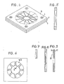
- Fig. 4 is a perspective view of the flexible container holder shown in Fig. 1, and in which a rectangular bottle is held by the holder;
- Fig. 5 is a cross-sectional view of a holding member;
- Fig. 6 is a plan view of another holding member;
- Fig. 7 is a cross-sectional view taken on line V-V of Fig. 18;
- Fig. 8 is a cross-sectional view of a further holding member;
- Fig. 9 is a cross-sectional view of a holding member in which a reinforcing member is inserted.
- Referring to Figs. 1-3, there is shown a container holder according to the present invention. The holder, generally indicated by reference numeral 5, has a
flexible holding member 1 for holding a container a. The holdingmember 1 is made from a material exhibiting a large frictional coefficient, such as synthetic resin, rubber, compound, or the like. The holdingmember 1 that is centrally formed with ahole 1b is divided into tongues 1a which extend radially inward. Anadaptor 2 which can be replaced with another adaptor or can be used for some kinds of containers sets the force with which the container s is held, according to the material, size, shape, and other characteristics of the container a. - The
adaptor 2 is made of a rectangular plate whose circular central portion has been cut off. A holdingframe 3 is similar in contour to theadaptor 2. The holdingmember 1 is sandwiched between theframe 3 and theadaptor 2, and these components are coupled together using bolts 4 or the like to form the holder 5. The material, thickness, shape of the holdingmember 1, and the number of the tongues 1a a can be selected at will according to the size, shape, weight, rigidity, material, and other characteristics of the container a retained by the holdingmember 1. Of course, the diameter of thehole 1 b at the center is set smaller than the outside diameter d. - The relation of a container a to the holder 5 is now described. Referring to Fig. 1, the container a is inserted into the
hole 1 b in the holding member - 1 from belowthe holder 5. Then, the container a is maintained in the condition shown in Fig. 2. At this time, the force applied to the container a to hold it can be arbitrarily set, depending on the outside diameter d of the container a, the amount of bend of the
flexible holding member 1, and the length x of the straight portion. Accordingly, in the present example, theadaptor 2 that cooperates with the holdingmember 1 can set the force with which the container is retained. - When the container having a diameter of d is handled, the inside diameter D1 of the holding
frame 3 and the inside diameter D2 of theadaptor 2 are determined as follows: - Di>d+(thickness of the holding member + length a of the gap)x2
- DZ?d+(thickness of the holding member + length x of the straight portion)x2 where a?x.
- If necessary, the inside diameter and shape of the
adaptor 2 can be determined so that the rigidity of the holding member may be circularly uniform. - When a container b (Fig. 3) having an outside diameter d1 larger than the outside diameter d of the container a (Fig. 2) is handled, an adaptor 2a having an inside diameter D2' is used in place of the
adaptor 2. In this case, the holdingmember 1 is bent to a larger extent, and the straight portion is shortened. As a result, the holdingmember 1 applies a larger force to the container b to hold it. In order to accommodate larger and heavier containers, an additional holder 5 can be received in a carrier as shown in Fig. 3. - When the container to be held is a square bottle, an
adaptor 19 as shown in Fig. 4 can be used. - In summary, the flexible holding member can be arbitrarily shaped according to the size of the handled container. It is essential that the holding member deform or bend freely in conformity to the container to hold and center the container. The force to retain the container is produced by deformation of the holding member, and increases or decreases according to the distance L between the front end 1a a of each tongue 1 a and the inner fringe of the adaptor 2 (Fig. 1). Also, the length of the portion of the holding member in contact with the container automatically increases or decreases, depending on the outside diameter of the container.
- The shape of the holding member can be varied in the manner described below.
- (1) The thickness is varied.
- (2) The number of the tongues 1a a is varied.
- (3) The cross section of the member is tapered off (Fig. 5).
- (4) The cross section is made concave to increase the force applied to the container by the bending holding member (Figs: 6 and 7).
- (5) The thickness is varied in a stepwise fashion in a radial direction to change the rigidity in a stepwise fashion (Fig. 8).
- (6) As shown in Fig. 9, a holding
member 20 comprises a cover member 22 in which a reinforcing member 21 is inserted. - Numerous kinds of holding members can be had by variously combining these items (1) (6).
- The novel flexible container holder designed as described above yields the following advantages.
- (1) Where the container holder is used in a bottling or canning line, the number of steps required is minimized. Also, the time taken to change one kind of holder to another in each step is reduced to a minimum.
- (2) Since several containers are carried simultaneously by a carrier, a conveyor which would heretofore been needed simply to convey containers can be dispensed with. Hence, the equipment can be made compact. Also, the equipment occupies much less space than conventional.
- (3) Since the outside diameter of the carriers is fixed, when one kind of container holder is switched to another, readjustment, a trial run of the production line, and so forth are unnecessary before the operation of the production line is started.
- (4) Since the setup of the first stage can be automated, as soon as the containers are withdrawn from the carrier, the next group of different containers can be mounted in the carrier.
- (5) No adjustments are required in handling containers. When the containers are bottles, they do not fall down, no does any other trouble take place. Therefore, the production line can run quite stably all day in the unattended condition.
Claims (6)
Applications Claiming Priority (6)
| Application Number | Priority Date | Filing Date | Title |
|---|---|---|---|
| JP159962/85 | 1985-07-19 | ||
| JP60159961A JPS6228353A (en) | 1985-07-19 | 1985-07-19 | Flexible vessel holder |
| JP159961/85 | 1985-07-19 | ||
| JP60159962A JPH0669830B2 (en) | 1985-07-19 | 1985-07-19 | Multi-container processing equipment |
| JP244790/85 | 1985-10-31 | ||
| JP60244790A JPS62106278A (en) | 1985-10-31 | 1985-10-31 | Method and device for heating or cooling product vessel, such as bottle or can and the like |
Related Child Applications (1)
| Application Number | Title | Priority Date | Filing Date |
|---|---|---|---|
| EP88105307.8 Division-Into | 1988-03-31 |
Publications (2)
| Publication Number | Publication Date |
|---|---|
| EP0209064A1 EP0209064A1 (en) | 1987-01-21 |
| EP0209064B1 true EP0209064B1 (en) | 1988-12-28 |
Family
ID=27321605
Family Applications (2)
| Application Number | Title | Priority Date | Filing Date |
|---|---|---|---|
| EP86109321A Expired EP0209064B1 (en) | 1985-07-19 | 1986-07-08 | Equipment for handling various containers |
| EP88105307A Expired - Lifetime EP0291674B1 (en) | 1985-07-19 | 1986-07-08 | An apparatus for handling containers |
Family Applications After (1)
| Application Number | Title | Priority Date | Filing Date |
|---|---|---|---|
| EP88105307A Expired - Lifetime EP0291674B1 (en) | 1985-07-19 | 1986-07-08 | An apparatus for handling containers |
Country Status (4)
| Country | Link |
|---|---|
| EP (2) | EP0209064B1 (en) |
| KR (1) | KR900000806B1 (en) |
| CN (1) | CN1017697B (en) |
| DE (3) | DE209064T1 (en) |
Families Citing this family (26)
| Publication number | Priority date | Publication date | Assignee | Title |
|---|---|---|---|---|
| DE3828664A1 (en) * | 1988-08-24 | 1990-03-01 | Eau De Cologne & Parfuemerie Fabrik 4711 | Tube holder |
| DE4328214C2 (en) * | 1993-08-21 | 1995-12-21 | Marc Osterwald | Process and treatment plant for the regeneration of spin-on filters |
| JP3338302B2 (en) * | 1996-09-06 | 2002-10-28 | 松下電器産業株式会社 | Holder for transporting cylindrical batteries |
| US6695569B2 (en) * | 1997-04-23 | 2004-02-24 | Certus Maschinenbau Gmbh | Device for collecting and palletizing bottles |
| DE29707324U1 (en) * | 1997-04-23 | 1998-09-03 | Certus Maschinenbau GmbH, 86316 Friedberg | Device for collecting and palletizing bottles |
| EP1073598B1 (en) | 1998-04-23 | 2001-09-05 | Certus Maschinenbau GmbH | Device for processing bottles |
| FR2810659B1 (en) * | 2000-06-27 | 2002-10-11 | Dev Ind Soc | HOLLOW BODY FILLING AND PACKAGING PLANT |
| US6920905B2 (en) | 2000-06-27 | 2005-07-26 | Societe Developpement Industriel | Installation for filling and packaging hollow bodies |
| FR2810654B1 (en) * | 2000-06-27 | 2002-11-08 | Dev Ind Soc | DEVICE FOR HANDLING HOLLOW BODIES |
| KR100345029B1 (en) * | 2001-11-09 | 2002-07-22 | 유병섭 | Machining method of a watch band and accessory |
| CN100471772C (en) * | 2005-10-19 | 2009-03-25 | 深圳易拓科技有限公司 | Automatic conveyor |
| FR2940254B1 (en) * | 2008-12-22 | 2013-04-26 | Joel Vazeille | CONVEYOR FOR BOTTLES |
| PL2399681T3 (en) * | 2010-06-25 | 2013-05-31 | R Bardi S R L | Method and apparatus for filling and rinsing containers and integrated plant for blowing, rinsing and filling containers |
| WO2013013212A1 (en) * | 2011-07-21 | 2013-01-24 | John Bean Technologies Corporation | Carriers for processing pouches and other irregular containers and objects |
| DE102013020638A1 (en) | 2013-12-16 | 2015-06-18 | Merck Patent Gmbh | Filling device and its use for filling a fluid |
| CN106144998A (en) * | 2016-08-18 | 2016-11-23 | 上海维托机械设备有限公司 | Adjustable mold for filling apparatus |
| EP3666403A1 (en) * | 2018-12-13 | 2020-06-17 | Gebo Packaging Solutions Italy SRL | A washing machine for washing empty containers and an operating method thereof |
| EP3666404B1 (en) * | 2018-12-13 | 2024-07-17 | Sidel Spa | A washing machine for washing empty containers and an operating method thereof |
| EP3666407B8 (en) * | 2018-12-13 | 2023-03-22 | Sidel S.p.A. | A cooling process for cooling hot washed containers in a washing machine and washing machine carrying out the same process |
| CN110775920A (en) * | 2019-11-14 | 2020-02-11 | 湖南尚源生物科技有限公司 | Filling device is used in production of organic purple rice wine |
| DE102020116266A1 (en) | 2020-06-19 | 2021-12-23 | Krones Aktiengesellschaft | Device and method for filling containers |
| PL247875B1 (en) * | 2021-09-27 | 2025-09-08 | Jasniewski Piotr | Handle for transporting tubairless packaging |
| CN115092535B (en) * | 2022-07-25 | 2023-08-29 | 四川省玻纤集团股份有限公司 | Packaging structure and packaging method for glass fiber or basalt yarn |
| IT202200020928A1 (en) * | 2022-10-11 | 2024-04-11 | Gruppo Bisaro Sifa Srl | CAN FILLING MACHINE AND METHOD FOR FILLING CANS. |
| GB2627748A (en) * | 2023-02-28 | 2024-09-04 | Enviro Cool Uk Ltd | Improvements in or relating to cooling |
| IT202300009756A1 (en) * | 2023-05-15 | 2024-11-15 | Kosme Srl Unipersonale | PLATE FOR A CAROUSEL MACHINE AND CAROUSEL MACHINE THAT INCLUDES IT |
Family Cites Families (8)
| Publication number | Priority date | Publication date | Assignee | Title |
|---|---|---|---|---|
| BE639825A (en) * | ||||
| DE524003C (en) * | 1931-05-01 | Willy Rueprich | Bottle handling machine | |
| US1724336A (en) * | 1928-09-24 | 1929-08-13 | John E Ayers | Bottle holder for bottle-washing machines |
| DE1182097B (en) * | 1962-09-28 | 1964-11-19 | Holstein & Kappert Maschf | Bottle basket for cleaning machines |
| DE1202160B (en) * | 1962-11-02 | 1965-09-30 | Seitz Werke Gmbh | Bottle washing machine |
| GB1505197A (en) * | 1976-04-06 | 1978-03-30 | Barry Wehmiller Co | Tandem bottle carrier assembly |
| FR2386460A1 (en) * | 1977-04-05 | 1978-11-03 | Manurhin | PARTS TRANSPORT VEHICLE, ESPECIALLY ON A CONTINUOUS KINEMATICS PROCESSING FACILITY |
| US4487312A (en) * | 1983-03-10 | 1984-12-11 | Owens-Illinois, Inc. | Package for carrying two multicontainer packs |
-
1986
- 1986-07-08 DE DE198686109321T patent/DE209064T1/en active Pending
- 1986-07-08 DE DE8888105307T patent/DE3677520D1/en not_active Expired - Lifetime
- 1986-07-08 DE DE8686109321T patent/DE3661525D1/en not_active Expired
- 1986-07-08 EP EP86109321A patent/EP0209064B1/en not_active Expired
- 1986-07-08 EP EP88105307A patent/EP0291674B1/en not_active Expired - Lifetime
- 1986-07-19 CN CN86105747A patent/CN1017697B/en not_active Expired
- 1986-07-19 KR KR1019860005873A patent/KR900000806B1/en not_active Expired
Also Published As
| Publication number | Publication date |
|---|---|
| CN1017697B (en) | 1992-08-05 |
| CN86105747A (en) | 1987-01-21 |
| DE209064T1 (en) | 1987-07-02 |
| KR870001100A (en) | 1987-03-11 |
| EP0291674B1 (en) | 1991-02-06 |
| EP0291674A1 (en) | 1988-11-23 |
| EP0209064A1 (en) | 1987-01-21 |
| KR900000806B1 (en) | 1990-02-17 |
| DE3661525D1 (en) | 1989-02-02 |
| DE3677520D1 (en) | 1991-03-14 |
Similar Documents
| Publication | Publication Date | Title |
|---|---|---|
| EP0209064B1 (en) | Equipment for handling various containers | |
| US5915524A (en) | Conveyor for a container filling/capping machine | |
| US12378023B2 (en) | Packaging system | |
| US4807421A (en) | Equipment for handling various containers | |
| US4884330A (en) | Assembly method | |
| US7299832B2 (en) | Rotary filling machine and related components, and related method | |
| US7278531B2 (en) | Flexible conveyor and connection elements | |
| US7264113B2 (en) | Pivotable conveyor and link | |
| US7261199B2 (en) | Neck gripping conveyor and link, and related rotary filler and system | |
| WO2006011896A1 (en) | System for securely conveying articles and related components | |
| KR100600927B1 (en) | Article grouping mechanism | |
| CA1323886C (en) | Container supply system | |
| CN101801793A (en) | Installation for filling cases with cross-partitions | |
| US5911303A (en) | Flight lug assembly | |
| US12534244B2 (en) | Feed system for container carrier applicating machine | |
| US12509262B2 (en) | Cut-off system for container carrier applicating machine | |
| EP2072406B1 (en) | Method and device for applying stickers | |
| US5485713A (en) | Method and apparatus for inserting partitions into article groups | |
| GB1595159A (en) | Container transfer system for bottling machines | |
| JPH0669830B2 (en) | Multi-container processing equipment | |
| US4932191A (en) | Apparatus and method for packing vials into a case positioned therebelow | |
| GB1486783A (en) | Process and equipment for packaging | |
| JP2901933B2 (en) | Boxing equipment | |
| CN211136221U (en) | Automatic installation equipment for piston clamp spring | |
| US4484774A (en) | Bottle carrier |
Legal Events
| Date | Code | Title | Description |
|---|---|---|---|
| PUAI | Public reference made under article 153(3) epc to a published international application that has entered the european phase |
Free format text: ORIGINAL CODE: 0009012 |
|
| 17P | Request for examination filed |
Effective date: 19860805 |
|
| AK | Designated contracting states |
Kind code of ref document: A1 Designated state(s): DE FR GB IT NL |
|
| ITCL | It: translation for ep claims filed |
Representative=s name: SOCIETA' ITALIANA BREVETTI S.P.A. |
|
| TCNL | Nl: translation of patent claims filed | ||
| EL | Fr: translation of claims filed | ||
| DET | De: translation of patent claims | ||
| 17Q | First examination report despatched |
Effective date: 19871127 |
|
| GRAA | (expected) grant |
Free format text: ORIGINAL CODE: 0009210 |
|
| AK | Designated contracting states |
Kind code of ref document: B1 Designated state(s): DE FR GB IT NL |
|
| REF | Corresponds to: |
Ref document number: 3661525 Country of ref document: DE Date of ref document: 19890202 |
|
| ET | Fr: translation filed | ||
| ITF | It: translation for a ep patent filed | ||
| PLBE | No opposition filed within time limit |
Free format text: ORIGINAL CODE: 0009261 |
|
| STAA | Information on the status of an ep patent application or granted ep patent |
Free format text: STATUS: NO OPPOSITION FILED WITHIN TIME LIMIT |
|
| 26N | No opposition filed | ||
| ITTA | It: last paid annual fee | ||
| REG | Reference to a national code |
Ref country code: GB Ref legal event code: 746 |
|
| ITPR | It: changes in ownership of a european patent |
Owner name: OFFERTA DI LICENZA AL PUBBLICO |
|
| REG | Reference to a national code |
Ref country code: FR Ref legal event code: DL |
|
| PGFP | Annual fee paid to national office [announced via postgrant information from national office to epo] |
Ref country code: GB Payment date: 19930625 Year of fee payment: 8 |
|
| PGFP | Annual fee paid to national office [announced via postgrant information from national office to epo] |
Ref country code: FR Payment date: 19930709 Year of fee payment: 8 |
|
| PGFP | Annual fee paid to national office [announced via postgrant information from national office to epo] |
Ref country code: DE Payment date: 19930719 Year of fee payment: 8 |
|
| PGFP | Annual fee paid to national office [announced via postgrant information from national office to epo] |
Ref country code: NL Payment date: 19930731 Year of fee payment: 8 |
|
| PG25 | Lapsed in a contracting state [announced via postgrant information from national office to epo] |
Ref country code: GB Effective date: 19940708 |
|
| PG25 | Lapsed in a contracting state [announced via postgrant information from national office to epo] |
Ref country code: NL Effective date: 19950201 |
|
| GBPC | Gb: european patent ceased through non-payment of renewal fee |
Effective date: 19940708 |
|
| NLV4 | Nl: lapsed or anulled due to non-payment of the annual fee | ||
| PG25 | Lapsed in a contracting state [announced via postgrant information from national office to epo] |
Ref country code: FR Effective date: 19950331 |
|
| PG25 | Lapsed in a contracting state [announced via postgrant information from national office to epo] |
Ref country code: DE Effective date: 19950401 |
|
| REG | Reference to a national code |
Ref country code: FR Ref legal event code: ST |
|
| PG25 | Lapsed in a contracting state [announced via postgrant information from national office to epo] |
Ref country code: IT Free format text: LAPSE BECAUSE OF NON-PAYMENT OF DUE FEES;WARNING: LAPSES OF ITALIAN PATENTS WITH EFFECTIVE DATE BEFORE 2007 MAY HAVE OCCURRED AT ANY TIME BEFORE 2007. THE CORRECT EFFECTIVE DATE MAY BE DIFFERENT FROM THE ONE RECORDED. Effective date: 20050708 |