EP0208609B2 - Process and apparatus for the catalytic cracking of hydrocarbons, with control of the reaction temperature - Google Patents
Process and apparatus for the catalytic cracking of hydrocarbons, with control of the reaction temperature Download PDFInfo
- Publication number
- EP0208609B2 EP0208609B2 EP86401464A EP86401464A EP0208609B2 EP 0208609 B2 EP0208609 B2 EP 0208609B2 EP 86401464 A EP86401464 A EP 86401464A EP 86401464 A EP86401464 A EP 86401464A EP 0208609 B2 EP0208609 B2 EP 0208609B2
- Authority
- EP
- European Patent Office
- Prior art keywords
- charge
- catalyst
- temperature
- injection
- cracking
- Prior art date
- Legal status (The legal status is an assumption and is not a legal conclusion. Google has not performed a legal analysis and makes no representation as to the accuracy of the status listed.)
- Expired - Lifetime
Links
Images


Classifications
-
- C—CHEMISTRY; METALLURGY
- C10—PETROLEUM, GAS OR COKE INDUSTRIES; TECHNICAL GASES CONTAINING CARBON MONOXIDE; FUELS; LUBRICANTS; PEAT
- C10G—CRACKING HYDROCARBON OILS; PRODUCTION OF LIQUID HYDROCARBON MIXTURES, e.g. BY DESTRUCTIVE HYDROGENATION, OLIGOMERISATION, POLYMERISATION; RECOVERY OF HYDROCARBON OILS FROM OIL-SHALE, OIL-SAND, OR GASES; REFINING MIXTURES MAINLY CONSISTING OF HYDROCARBONS; REFORMING OF NAPHTHA; MINERAL WAXES
- C10G11/00—Catalytic cracking, in the absence of hydrogen, of hydrocarbon oils
- C10G11/14—Catalytic cracking, in the absence of hydrogen, of hydrocarbon oils with preheated moving solid catalysts
- C10G11/18—Catalytic cracking, in the absence of hydrogen, of hydrocarbon oils with preheated moving solid catalysts according to the "fluidised-bed" technique
- C10G11/187—Controlling or regulating
-
- C—CHEMISTRY; METALLURGY
- C10—PETROLEUM, GAS OR COKE INDUSTRIES; TECHNICAL GASES CONTAINING CARBON MONOXIDE; FUELS; LUBRICANTS; PEAT
- C10G—CRACKING HYDROCARBON OILS; PRODUCTION OF LIQUID HYDROCARBON MIXTURES, e.g. BY DESTRUCTIVE HYDROGENATION, OLIGOMERISATION, POLYMERISATION; RECOVERY OF HYDROCARBON OILS FROM OIL-SHALE, OIL-SAND, OR GASES; REFINING MIXTURES MAINLY CONSISTING OF HYDROCARBONS; REFORMING OF NAPHTHA; MINERAL WAXES
- C10G11/00—Catalytic cracking, in the absence of hydrogen, of hydrocarbon oils
- C10G11/14—Catalytic cracking, in the absence of hydrogen, of hydrocarbon oils with preheated moving solid catalysts
- C10G11/18—Catalytic cracking, in the absence of hydrogen, of hydrocarbon oils with preheated moving solid catalysts according to the "fluidised-bed" technique
-
- Y—GENERAL TAGGING OF NEW TECHNOLOGICAL DEVELOPMENTS; GENERAL TAGGING OF CROSS-SECTIONAL TECHNOLOGIES SPANNING OVER SEVERAL SECTIONS OF THE IPC; TECHNICAL SUBJECTS COVERED BY FORMER USPC CROSS-REFERENCE ART COLLECTIONS [XRACs] AND DIGESTS
- Y10—TECHNICAL SUBJECTS COVERED BY FORMER USPC
- Y10S—TECHNICAL SUBJECTS COVERED BY FORMER USPC CROSS-REFERENCE ART COLLECTIONS [XRACs] AND DIGESTS
- Y10S208/00—Mineral oils: processes and products
- Y10S208/01—Automatic control
Definitions
- the present invention relates to catalytic cracking of hydrocarbon charges in a fluidized bed. It relates more particularly to a process and a device for such catalytic cracking, with regulation of the reaction temperature by quenching the reaction products.
- the catalyst of the FCC process and the feedstock to be treated are brought into contact at the base of a reactor made up of a column known as a "charge lift", which techniques often designate by the English term “riser”. .
- a charge lift which techniques often designate by the English term “riser”.
- At the top of the column is an enclosure concentric with the elevator.
- a ballistic separation system to recover the catalyst entrained with the vapors.
- Cyclonic systems are generally used.
- the charge is discharged at the top of said enclosure, while the catalyst particles deactivated by coke deposition are collected at the base of the enclosure and meet there a stripping fluid such as water vapor, injected at the base from said enclosure, before being evacuated to a regenerator, in order to restore their activity by burning coke.
- Combustion air is injected at the base of the regenerator, while at the top of the latter are provided cyclones making it possible to separate the combustion gas from the entrained particles of the regenerated catalyst.
- This is evacuated at the bottom of the regenerator and recycled to the base of the elevator or "riser", where the charge is usually injected at a temperature between 80 ° C and 400 ° C and under a pressure ranging from 0 , 78105 to 3.5 • 10 5 relative Pascals.
- the pair “charge preheating temperature / regenerated catalyst circulation” is therefore adjusted so as to determine the reaction temperature in any reaction zone, and in particular at the outlet of the riser.
- the catalyst can be introduced with the charge at the top of an essentially descending or “dropper” reaction column, at the base of which the spent catalyst is recovered, stripped sent for regeneration.
- US-A-3,896,024 describes a process for catalytic cracking of a charge, the boiling point of which is between 650 and 720 ° F (343 and 382 ° C).
- the charge is brought into contact with the catalyst in a rising flow column where the temperature of the mixture can reach at most 1000 FF (538 ° C.).
- the charge is thermally cracked into fractions of lower boiling points.
- a charge of preheated gas oil is injected into the column to lower the temperature of the reaction mixture between 800 and 900 °. Mp (426 and 482 ° C).
- the mixture obtained is then catalytically cracked under milder conditions in the upper part of the column.
- Petroleum charges characterized in that at least 10% of their weight has a boiling point above 500 ° C., have thus been able to be treated in the catalytic cracking units, by virtue of an increase in the temperature in the zone of injecting the catalyst and of the charge to be cracked (or “mixing zone”) and of a good spraying of the charge in this zone.
- the heterogeneity of the temperatures which results from such an injection, necessitated the development of reactors with short residence times, in order to avoid the occurrence of overcracking or of secondary reactions, such as reactions polymerization of cracked products, as well as to avoid the production of an excess of gases which are difficult to recover.
- the temperature regulation carried out according to the invention therefore makes it possible to control the duration of the contact between the molecules to be catalytically cracked and the catalyst, and thus to avoid excessive prolongation of the thermocracking generating coke and light gases, as well as the occurrence of side reactions linked to an unsuitable catalytic cracking temperature.
- An object of the present invention is therefore, in a process for catalytic cracking of a charge of hydrocarbons in a fluidized bed, to bring the charge and the catalyst into contact at a high temperature capable of preventing deposits of coke on the catalyst and optimally promote catalytic cracking of this charge.
- Another object of the invention is to control the contact time of the catalyst and of the charge at this elevated temperature, so as to decrease: the secondary reactions or to limit the thermocracking liable to occur.
- the subject of the invention is therefore a process for the catalytic cracking of a heavy load of hydrocarbons, more than 10% by weight of which has a boiling point above 500 ° C., this process comprising a phase of bringing into contact in a diluted fluidized bed and with short contact time with ascending or descending flow in a column, under cracking conditions, of said charge and of particles of a cracking catalyst, a phase of separation of spent catalyst and of cracked charge downstream of the injection zone of said charge, at least one phase of stripping of the spent catalyst, then a phase of regeneration of said catalyst under conditions of combustion of the coke deposited on it and, finally, a phase of recycling of the catalyst regenerated at l feeding said column, this process being characterized in that injected into said column of regenerated catalyst under conditions such that the equilibrium temperature resulting from the mixture of the vaporized charge and the catalyst is at least greater than 500 ° C and at least 40 to 100 ° C above the final reaction temperature at the end of the column, and in that one injects downstream of this
- the injection of the auxiliary fluid being carried out at such a distance from the injection of the charge that the resulting lowering of temperature takes place less than a second after the injection of the charge and preferably less than half a second after this injection.
- the injected fluid may be a liquid or a gas and, in particular, water, steam, or any hydrocarbon vaporizable under the injection conditions, in particular, coking or visbreaking gas oils , catalytic diluents, heavy aromatic solvents, as well as certain deasphalting cuts extracted with heavy solvent.
- this fluid will therefore have a selective quenching effect on the reaction mixture constituted by the charge and the grains of catalyst, and the injection rate of said fluid must be such that it allows regulation, under optimum conditions, the temperature of the catalytic cracking reaction, without harming the subsequent stripping of the spent catalyst and without causing condensation on the catalyst particles of the heaviest hydrocarbons present, which would result in an increased deposition of coke on the catalyst.
- the fluid injection conditions will be such that it causes an instantaneous lowering of the temperature of the reaction mixture of the order of 10 to 70 ° C. which, at constant final reaction temperature, therefore results in a substantially increased equivalent of the mixing temperature between the charge to be cracked and the grains of regenerated catalyst.
- the process according to the invention can be implemented both in an upward cracking column (riser, also called “riser”) and in a column down flow.
- An important advantage of the process according to the invention is that it makes it possible to limit the catalyst regeneration temperature, due to a reduced deposition of coke, and makes it possible to convert heavy charges normally excluded in the catalytic cracking process into fluidized bed.
- the conditions for injecting the charge and the catalyst will be such that the mixing temperature will be slightly higher than the vaporization temperature of the charge.
- the conditions of injection of the quenching auxiliary fluid in particular, the flow rate, the temperature and the pressure, will have to be adjusted as a function of the characteristics of the charge and of the catalyst, as well as of the conditions of catalytic cracking reaction and of the desired temperature profile. that is to say in practice as a function of the mixing temperature and of the desired final reaction temperature.
- a preferred embodiment of the process according to the invention therefore consists in regulating the injection of said auxiliary fluid into the cracking column so that the reaction temperature which results from this injection is maintained at a value predetermined and constant, but high enough that the effectiveness of stripping is not substantially impaired.
- the invention also relates to a device for implementing the method defined above, this device comprising a cracking column with ascending or descending flow, means for supplying said column under pressure with a hydrocarbon charge and particles of a regenerated cracking catalyst, means for separating the products from the cracked charge and spent catalyst particles, at least one means for stripping spent catalyst particles with at least one fluid, at least one unit for regenerating said catalyst catalyst by combustion of the coke deposited thereon, means for recycling the regenerated catalyst to said supply means and, downstream of the zone of mixing in said column of the hydrocarbon feedstock and the particles of regenerated catalyst, at least one means for injecting an auxiliary fluid under flow, temperature and pressure conditions, such as the injection of this auxiliary fluid decreases the temperature of the reaction zone immediately immediately downstream independently of the mixing temperature, this device being characterized in that it comprises means for regulating the flow rate of said auxiliary fluid so that the temperature of the reaction zone in downstream of the injection of the auxiliary fluid is maintained at a set value which is specific to the nature of the charge to be cracked
- this device will also include means for increasing the flow rate of the hot catalyst when the final reaction temperature tends to decrease relative to the set value.
- the means for injecting an auxiliary fluid may advantageously be located in the reaction zone at a distance which may be between 0.1 and 0.8 times the length of said reaction zone and, preferably, between 0.1 and 0.5 times this length, downstream of the injection site of the load to be cracked.
- This or these injection means will advantageously consist of an injection device of a type known per se, making it possible to distribute the fluid in a homogeneous manner over the entire section of the reaction zone.
- the quantities necessary for regulating the mixing temperature will be injected using a spraying device making it possible, in a manner known per se, to spray this liquid in the form very fine fog over the entire section of the zone reacts in such a way as to obtain a heat transfer as instantaneous as possible.
- a spraying device making it possible, in a manner known per se, to spray this liquid in the form very fine fog over the entire section of the zone reacts in such a way as to obtain a heat transfer as instantaneous as possible.
- the flow rate necessary to achieve an identical increase in temperature will be from 100 to 700 liters of hydrocarbon per cubic meter of charge treated.
- the regenerated catalyst is injected via a pipe 1 at the base of an ascending flow column 2 or “riser”, as well as a carrier gas injected at 3
- the load of hydrocarbons to be treated is itself injected in 4 at the base of the column and the hydrocarbons and particles of the catalyst are in contact in zone 2, immediately downstream of the injection of the feed.
- the temperature of the catalyst-vaporized charge mixture is between approximately 500 and 650 ° C., depending on the nature of the charge and the desired conversion objectives.
- an enclosure 6 for separating the cracked products and the spent catalyst particles.
- injectors 7 of a stripping fluid generally water vapor, acting against the current of the separated catalyst particles.
- the catalyst particles are removed at 8 to a second stripping device or to a regenerator, while the cracked products are removed at the upper part (not shown) of enclosure 6.
- an auxiliary quenching fluid for the cracked products is injected at 9 into part 5 of column 2, downstream of the contact zone between catalyst particles and vaporized charge.
- This auxiliary fluid - water, water vapor, hydrocarbons, or other - is injected at a rate such that it lowers from 10 to 70 ° C, depending on the desired result, the temperature of the mixture, in order to optimize the reactions catalytic cracking of the charge.
- the final temperature of the reaction zone thus cooled may be, for example, of the order of 500 ° C, but must be higher than the dew point of the heaviest hydrocarbons present.
- a temperature probe 10 will be provided inside the enclosure 6 to measure the temperature there and to optionally control the valve 12 controlling the flow of the auxiliary fluid in the supply line 13 of the injection means. 9, in such a way that the temperature in the enclosure 6 is maintained above a set temperature specific to the type of load treated.
- the cracking column 20 is of the so-called “dropper” type, that is to say that the particles of regenerated catalyst 21 are injected into the upper part of the column 20 and fall there by gravity .
- the load to be cracked is also introduced into the upper part of the column at 22.
- An enclosure 23 situated at the base of the column 20 makes it possible to separate and evacuate the effluents, namely the products of cracking through the pipe 24, and the spent catalyst particles towards the base of this enclosure 23, in order to strike them, then convey them to the regeneration.
- an auxiliary fluid for quenching the cracked products is injected at 26, downstream of the means 22 for injecting the charge. Its flow rate is such that for a given mixing temperature, it lowers the final reaction temperature by approximately 10 to 70 ° C., to allow the catalytic cracking reactions to be carried out under optimal conditions.
- a temperature probe 27, arranged before the pipe 24, makes it possible to control, by a valve 29 arranged on the supply pipe 30, the flow of auxiliary fluid of the injection means 26, in such a way that the rewashed temperature at 27 is constantly equal to or higher than a set temperature, while the probe makes it possible to act on the infection temperature in the reaction zone and on the regulation of the injection rate at 26.
- the cracking column 2 is again of the riser type and the reference numerals designating the elements of the unit are the same as for those of FIG. 1.
- This figure presents a simplified and particularly advantageous mode of regulation. , according to the present invention.
- the auxiliary fluid is injected at 9, or when the injection volume is increased, the final temperature of the catalytic reaction, measured at 10, will tend to decrease compared to the desired setpoint for the corresponding charge.
- the valve 16, acting on the flow of hot regenerated catalyst will immediately ensure an increase in the mixing temperature which, taking into account the flow injected at 9, will make it possible to bring the final cracking temperature back to the set value.
- the following two examples illustrate the advantages of the process according to the invention.
- a commercial catalyst is used for cracking, comprising zeolites with high stability and a matrix capable of cracking the heaviest hydrocarbon molecules under cracking conditions.
- the table above shows the advantage resulting from raising the initial cracking temperature above 550 ° C. and quenching the reaction products, using water, to bring the temperature down. of the mixture at 525 ° C.
- the auxiliary fluid this time consists of a recycling of cracking effluents with a boiling point of between 340 ° C. and 460 ° C., carried out 0.2 seconds after injection of the charge into the mixing zone.
- the operating conditions are as follows:
- the heavy load considered could not have been treated without resorting to the means used in the present invention, insofar as, according to the prior art, at least 15% by weight of this load could not have been be vaporized, which would have led to a production of coke outside the limits compatible with the satisfaction of the thermal balance of the unit.
- the mixing temperature was increased by approximately 40 ° C to ensure complete vaporization and the thermal shock conditions necessary for cracking the heaviest compounds present in this charge, after which the spraying of a hydrocarbon in the reaction medium allows reduce the final temperature to 510 ° C and thus ensure optimal conversion.
- the process according to the invention therefore makes it possible to improve the performance of a cracking unit for a determined charge of hydrocarbons. It can advantageously be used to treat these heavier and more contaminated loads with greater efficiency. Likewise, this process has an exceptional appeal for the treatment of nitrogenous charges, rich in polar compounds (resins, asphaltenes), where the strong presence of aromatic nitrogen is responsible for a spectacular drop in conversion. On a Nigerian KOLE residue, for example, the conversion gain with the process according to the invention is around 5.5% by volume. This is explained by the higher mixing temperature, which favorably displaces the adsorption balance of the aromatic nitrogen, thereby reducing the neutralization of certain acid sites of the catalyst.
Description
La présente invention concerne le craquage catalytique de charges d'hydrocarbures en lit fluidisé. Elle a plus particulièrement pour objet un procédé et un dispositif pour un tel craquage catalytique, avec une régulation de la température réactionnelle par trempe des produits de la réaction.The present invention relates to catalytic cracking of hydrocarbon charges in a fluidized bed. It relates more particularly to a process and a device for such catalytic cracking, with regulation of the reaction temperature by quenching the reaction products.
On sait que, dans les procédés dits de craquage catalytique (en anglais Fluid Catalytic Cracking, ou encore procédé FCC), la charge d'hydrocarbures est complètement vaporisée par mise en contact à haute température avec un catalyseur de craquage approprié maintenu en suspension. Après que l'on ait atteint par craquage la gamme de poids moléculaires désirée, avec un abaissement correspondant des points d'ébullition, le catalyseur est rapidement séparé des produits obtenus.It is known that, in the so-called catalytic cracking processes (in English Fluid Catalytic Cracking, or FCC process), the hydrocarbon charge is completely vaporized by contacting at high temperature with an appropriate cracking catalyst kept in suspension. After the desired molecular weight range has been reached by cracking, with a corresponding lowering of the boiling points, the catalyst is rapidly separated from the products obtained.
Dans la pratique, le catalyseur du procédé FCC et la charge à traiter sont mis en contact à la base d'un réacteur constitué d'une colonne dite «élévateur de charge», que les techniques désignent souvent par le terme anglais de «riser». Au sommet de la colonne est disposée un enceinte concentrique à l'élévateur. Dans la partie supérieure de cette enceinte et au-dessus de l'élévateur est logé un système de séparation balistique, pour récupérer le catalyseur entraîné avec les vapeurs. Des systèmes cycloniques sont généralement utilisés. La charge est évacuée au sommet de ladite enceinte, tandis que les particules de catalyseur désactivées par dépôt de coke sont rassemblées à la base de l'enceinte et y rencontrent un fluide de strippage tel que de la vapeur d'eau, injecté à la base de ladite enceinte, avant d'être évacuées vers un régénérateur, en vue de restaurer leur activité par brùlage du coke. De l'air de combustion est injecté à la base du régénérateur, tandis qu'à la partie supérieure de celui-ci sont prévus des cyclones permettant de séparer le gaz de combustion des particules entraînées du catalyseur régénéré. Celui-ci est évacué à la partie inférieure du régénérateur et recyclé vers la base de l'élévateur ou «riser», où la charge est habituellement injectée à une temperature comprise entre 80 ° C et 400 ° C et sous une pression allant de 0,78105 à 3,5• 105 Pascals relatifs.In practice, the catalyst of the FCC process and the feedstock to be treated are brought into contact at the base of a reactor made up of a column known as a "charge lift", which techniques often designate by the English term "riser". . At the top of the column is an enclosure concentric with the elevator. In the upper part of this enclosure and above the elevator is housed a ballistic separation system, to recover the catalyst entrained with the vapors. Cyclonic systems are generally used. The charge is discharged at the top of said enclosure, while the catalyst particles deactivated by coke deposition are collected at the base of the enclosure and meet there a stripping fluid such as water vapor, injected at the base from said enclosure, before being evacuated to a regenerator, in order to restore their activity by burning coke. Combustion air is injected at the base of the regenerator, while at the top of the latter are provided cyclones making it possible to separate the combustion gas from the entrained particles of the regenerated catalyst. This is evacuated at the bottom of the regenerator and recycled to the base of the elevator or "riser", where the charge is usually injected at a temperature between 80 ° C and 400 ° C and under a pressure ranging from 0 , 78105 to 3.5 • 10 5 relative Pascals.
Le procédé FCC est naturellement mis en oeuvre de façon que l'unité de craquage soit en équilibre thermique, toute la chaleur nécessaire étant apportée par la combustion du coke déposé au cours de la réaction de craquage sur les grains du catalyseur. Autrement dit, l'alimentationen en catalyseur chaud régénéré et la température d'injection de la charge à craquer doivent être telles que l'unité puisse répondre aux diverses exigences thermiques de la section réactionnelle, à savoir, en particulier:
- - la vaporisation de la charge.
- - l'apport de chaleur exigé par les réactions impliquées, lesquelles, globalement, sont endothermiques.
- - les pertes de chaleur de l'unité.
- - vaporization of the charge.
- - the heat input required by the reactions involved, which, overall, are endothermic.
- - heat losses from the unit.
Le couple «température de préchauffage de la charge/circulation de catalyseur régénéré» est donc ajusté de façon à déterminer la température de réaction dans toute zone réactionnelle, et en particulier en sortie du riser.The pair “charge preheating temperature / regenerated catalyst circulation” is therefore adjusted so as to determine the reaction temperature in any reaction zone, and in particular at the outlet of the riser.
En variante, le catalyseur peut être introduit avec la charge au sommet d'une colonne de réaction essentiellement descendante ou «dropper», à la base de laquelle le catalyseur usé est récupéré, strippé a envoyé à la régénération.As a variant, the catalyst can be introduced with the charge at the top of an essentially descending or “dropper” reaction column, at the base of which the spent catalyst is recovered, stripped sent for regeneration.
US-A-3 896 024 décrit un procédé de craquage catalytique d'une charge dont le point d'ébullition est compris entre 650 et 720 ° F (343 et 382 ° C). La charge est mise en contact avec le catalyseur dans une colonne à flux montant où la température du mélange peut atteindre au plus 1000 F F (538 °C). Dans cette zone de mélange, la charge est craquée thermiquement en fractions de points d'ébullition inférieurs, En aval de cette zone, une charge de gas-oil préchauffée est injectée dans la colonne pour abaisser la température du mélange réactionnel entre 800 et 900 ° F (426 et 482 ° C). Le mélange obtenu est ensuite craqué catalytiquement dans des conditions plus douces dans la partie supérieure de la colonne.US-A-3,896,024 describes a process for catalytic cracking of a charge, the boiling point of which is between 650 and 720 ° F (343 and 382 ° C). The charge is brought into contact with the catalyst in a rising flow column where the temperature of the mixture can reach at most 1000 FF (538 ° C.). In this mixing zone, the charge is thermally cracked into fractions of lower boiling points. Downstream of this zone, a charge of preheated gas oil is injected into the column to lower the temperature of the reaction mixture between 800 and 900 °. Mp (426 and 482 ° C). The mixture obtained is then catalytically cracked under milder conditions in the upper part of the column.
Les développements les plus récents an matière de craquage catalytique n'ont cependant permis de résoudre que partiellement le problème d'injection des charges pétrolières lourdes dans les unités de craquage catalytique.The most recent developments in catalytic cracking have, however, only partially resolved the problem of injecting heavy petroleum charges into the catalytic cracking units.
On sait, en effet, que plus la charge pétrolière à craquage possède un point d'ébullition élevé, plus elle possède de composés à haut poids moléculaire et riches on métaux, qui sont des précurseurs de coke: ces composés, qui comprennent des asphaltènes ont une nature cyclique ou polycyclique et présentent la particularité d'être difficiles à vaporiser dans les conditions usuelles d'injection, et par conséquent de former des dépôts de coke importants lorsqu'il sont mis en présence des grains de catalyseur, an vue de la réaction de craquage catalytique.We know, in fact, that the higher the cracked petroleum charge has a higher boiling point, the more it has high molecular weight and metal-rich compounds, which are coke precursors: these compounds, which include asphaltenes, have cyclic or polycyclic in nature and have the particularity of being difficult to vaporize under the usual injection conditions, and consequently of forming significant coke deposits when they are brought into contact with the catalyst grains, in view of the reaction catalytic cracking.
Une première solution a donc été proposée (brevet US 4 427 537), selon laquelle des charges petrolières lourdes, possédant en particulier des quantités importantes d'aspaltènes, pouvaient être cra- quees on améliorant leur pulvérisation dans la zone d'injection du catalyseur, da façon à créer, lors du contact avec les grains de catalyseur, un choc thermique suffisant pour permettre un thermocraquage des molècules à poids moléculaire élevé. La scission thermique de ces molécules en molécules plus petites permet à ces dernières d'être ensuite recraquées catalytiquement en phase gazeuse, lors de leur mise en présence des grains de catalyseur.A first solution has therefore been proposed (US Pat. No. 4,427,537), according to which heavy petroleum fillers, in particular having significant quantities of aspaltenes, could be cracked by improving their spraying in the zone of injection of the catalyst, da so as to create, upon contact with the catalyst grains, a sufficient thermal shock to allow thermocracking of the high molecular weight molecules. The thermal cleavage of these molecules into smaller molecules allows the latter to be then catalytically recreated in the gas phase, when they are placed in the presence of the catalyst grains.
Des charges pétrolières, caractérisées en ce qu'au moins 10% de leur poids possède un point d'ébullition supérieur à 500 ° C, ont ainsi pu être traitées dans les unités de craquage catalytique, grâce à une augmentation de la température dans la zone d'injection du catalyseur et de charge à craquer (ou «zone de mélange») et à une bonne pulvérisation de la charge dans cette zone. Cependant, l'hétérogénéité des températures, qui résulte d'une telle injection, a nécessité la mise au point de réacteurs à courts temps de séjour, afin d'éviter l'occurence d'un surcraquage ou de réactions secondaires, telles que des réactions de polymérisation des produits craqués, ainsi que pour éviter la production d'un excès de gaz difficiles à valoriser.Petroleum charges, characterized in that at least 10% of their weight has a boiling point above 500 ° C., have thus been able to be treated in the catalytic cracking units, by virtue of an increase in the temperature in the zone of injecting the catalyst and of the charge to be cracked (or “mixing zone”) and of a good spraying of the charge in this zone. However, the heterogeneity of the temperatures, which results from such an injection, necessitated the development of reactors with short residence times, in order to avoid the occurrence of overcracking or of secondary reactions, such as reactions polymerization of cracked products, as well as to avoid the production of an excess of gases which are difficult to recover.
En poursuivant ses travaux sur le craquage catalytique des charges pétrolières lourdes, la Demanderesse a mis en évidence le fait que cette première solution ne résolvait que partiellement le problème du craquage des charges lourdes particulièrement difficiles à valoriser, par exemple celles dont 10% du poids possède un point d'ébullition supérieur à 550°C, car la chaleur nécessaire au thermocraquage des molécules lourdes devenait tellement importante que la vitesse de réaction, liée à la température de mélange dans la zone d'injection de a charge à craquer, nécessitait un temps de séjour limité à quelques secondes seulement, d'où un contrôle très difficile des conditions de la réaction avec les moyens actuels.By continuing its work on the catalytic cracking of heavy petroleum charges, the Applicant has highlighted the fact that this first solution only partially solved the problem of cracking heavy charges which are particularly difficult to recover, for example those of which 10% by weight has a boiling point above 550 ° C, because the heat necessary for the thermocracking of heavy molecules became so great that the reaction rate, linked to the mixing temperature in the injection zone of the charge to be cracked, required time stay limited to only a few seconds, hence very difficult control of the reaction conditions with current means.
Il a cependant été établi par la Demanderesse que la craquage des charges lourdes peut être effectué de façon simple et efficace en assurant une régulation appropriée de la température dans la zone réactionnelle, grâce à laquelle:
- - un choc thermique maximum est effectué à l'injection pendant une durée très courte mais suffisante pour permettre la conversion thermique des molécules à poids moléculaire élevé et notamment des asphaltènes présents dans la charge, et une meilleure vaporisation des molécules destinées à être craqués catalytiquement, puis.
- - la température de la réaction catalytique souhaitée et maintenue et reste indépendante de celle qui résulte de l'injection du catalyseur et de la charge craquer, par introduction, en aval de la zone d'injection de la charge, d'un fluide auxiliaire, dans des conditions telles de débit, de température et de pression, que l'introduction de ce fluide permette à la réaction de craquage catalytique de s'effectuer dans des conditions plus douces et indépendantes de la température de mélange.
- a maximum thermal shock is effected on injection for a very short time but sufficient to allow the thermal conversion of the molecules with high molecular weight and in particular of the asphaltenes present in the feed, and better vaporization of the molecules intended to be catalytically cracked, then.
- the temperature of the desired and maintained catalytic reaction and remains independent of that which results from the injection of the catalyst and of the cracked charge, by introduction, downstream of the charge injection zone, of an auxiliary fluid, under conditions such as flow rate, temperature and pressure, that the introduction of this fluid allows the catalytic cracking reaction to be carried out under milder conditions and independent of the mixing temperature.
Cette régulation présente un double avantage:
- - d'une part, l'augmentation substantielle de la température de mélange dans la zone d'injection de la charge lourde sur le catalyseur permet une meilleure vaporisation de celle-ci et un craquage thermique instantané des composés les plus lourds, ce quidiminue la formation de coke sur les grains de catalyseurs, liée en particulier au fait que les composés à haut point d'ébullition, ou à caractère basique (composés aromatiques azotés, hydrocarbures aromatiques condensés etc.), ont tendance à s'adsorber et à neutraliser certains sites acides de catalyseur:
- - d'autres part, si le thermocraquage des molécules les plus lourdes est réalisé de façon quasi- instantanée à haute température, les composés plus légers, en provenance soit de la charge elle-même, soit de la réaction ne thermocraquage, doivent être craqués catalytiquement, par contact avec les sites actifs de grains de catalyseur, au cours d'une réaction plus lente, dont l'optimum de température n'est pas nécesairement celui qui résulte des conditions précédemment évoquées.
- on the one hand, the substantial increase in the mixing temperature in the injection zone of the heavy load on the catalyst allows better vaporization of the latter and instantaneous thermal cracking of the heaviest compounds, which reduces the formation of coke on the grains of catalysts, linked in particular to the fact that compounds with a high boiling point, or with a basic character (aromatic nitrogen compounds, condensed aromatic hydrocarbons etc.), tend to adsorb and neutralize certain acid catalyst sites:
- - on the other hand, if the heavier cracking of the heaviest molecules is carried out almost instantaneously at high temperature, the lighter compounds, coming either from the charge itself, or from the non-cracking reaction, must be cracked catalytically, by contact with the active sites of catalyst grains, during a slower reaction, the optimum temperature of which is not necessarily that which results from the conditions mentioned above.
La régulation de la température conduite selon l'invention permet donc de contrôler la durée du contact entre les molécules à craquer catalytiquement et le catalyseur, et d'éviter ainsi une prolongation excessive du thermocraquage générateur de coke et du gaz légers, ainsi que l'occurence de réactions secondaires liées à une température de craquage catalytique inadaptée.The temperature regulation carried out according to the invention therefore makes it possible to control the duration of the contact between the molecules to be catalytically cracked and the catalyst, and thus to avoid excessive prolongation of the thermocracking generating coke and light gases, as well as the occurrence of side reactions linked to an unsuitable catalytic cracking temperature.
Un but de la présente invention est, par conséquent, dans un procédé de craquage catalytique d'une charge d'hydrocarbures en lit fluidisé, de mettre en contact la charge et le catalyseur à une température élevée apte à prévenir les dépôts de coke sur le catalyseur et à favoriser de façon optimum le craquage catalytique de cette charge.An object of the present invention is therefore, in a process for catalytic cracking of a charge of hydrocarbons in a fluidized bed, to bring the charge and the catalyst into contact at a high temperature capable of preventing deposits of coke on the catalyst and optimally promote catalytic cracking of this charge.
Un autre but de l'invention est de contrôler la durée de contact du catalyseur et de la charge à cette température élevée, de façon à diminue: les réactions secondaires ou à limiter le thermocraquage susceptible de se produire.Another object of the invention is to control the contact time of the catalyst and of the charge at this elevated temperature, so as to decrease: the secondary reactions or to limit the thermocracking liable to occur.
L'invention a par conséquent pour objet un procédé de craquage catalytique d'une charge lourde d'hydrocarbures, dont plus de 10 % en poids possède un point d'ébullition supérieur à 500 ° C, ce procédé comprenant une phase de mise en contact en lit fluidisé dilué et à court temps de contact à flux ascendant ou descendant dans une colonne, dans des conditions de craquage, de ladite charge et de particules d'un catalyseur de craquage, une phase de séparation de catalyseur usé et de la charge craquée en aval de la zone d'injection de ladite charge, au moins une phase de strippage du catalyseur usé, puis une phase de régénération dudit catalyseur dans des conditions de combustion du coke déposé sur celui-ci et, enfin, une phase de recyclage du catalyseur régénéré à l'alimentation de ladite colonne, ce procédé étant caractérisé en ce que l'on injecte dans ladite colonne du catalyseur régénéré dans des conditions telles que la température d'équilibre résultant du mélange de la charge vaporisée et du catalyseur soit au moins supérieure à 500 ° C et au moins supérieure de 40 à 100 ° C à la température finale de réaction en fin de colonne, et en ce que l'on injecte en aval de cette zone de mélange, mais en amont de la phase de séparation, un fluide auxiliaire vaporisable dans les conditions de l'injection, de façon telle que la température du mélange de la charge vaporisée et des particules du catalyseur soit abaissée d'environ 10 à 70 ° C par rapport à la température initiale qui résulte de la mise en contact du catalyseur et de la charge, de manière à permettre à la réaction de craquage catalytique de s'effectuer dans des conditions plus douces et indépendantes de ladite température initiale, la température finale de réaction étant toutefois supérieure au point de rosée des hydrocarbures présents les plus lourds, l'injection du fluide auxiliaire étant effectuée à une distance telle de l'injection de la charge que l'abaissement de température en résultant a lieu moins d'une seconde après l'injection de la charge et de préférence moins d'une demi-seconde après cette injection.The subject of the invention is therefore a process for the catalytic cracking of a heavy load of hydrocarbons, more than 10% by weight of which has a boiling point above 500 ° C., this process comprising a phase of bringing into contact in a diluted fluidized bed and with short contact time with ascending or descending flow in a column, under cracking conditions, of said charge and of particles of a cracking catalyst, a phase of separation of spent catalyst and of cracked charge downstream of the injection zone of said charge, at least one phase of stripping of the spent catalyst, then a phase of regeneration of said catalyst under conditions of combustion of the coke deposited on it and, finally, a phase of recycling of the catalyst regenerated at l feeding said column, this process being characterized in that injected into said column of regenerated catalyst under conditions such that the equilibrium temperature resulting from the mixture of the vaporized charge and the catalyst is at least greater than 500 ° C and at least 40 to 100 ° C above the final reaction temperature at the end of the column, and in that one injects downstream of this mixing zone, but upstream of the separation phase, an auxiliary fluid vaporizable under the conditions of the injection, so that the temperature of the mixture of the vaporized charge and the particles of the catalyst is lowered by about 10 to 70 ° C. relative to the t initial temperature which results from the contacting of the catalyst and the charge, so as to allow the catalytic cracking reaction to take place under milder conditions and independent of said initial temperature, the final reaction temperature however being higher at the dew point of the heaviest hydrocarbons present, the injection of the auxiliary fluid being carried out at such a distance from the injection of the charge that the resulting lowering of temperature takes place less than a second after the injection of the charge and preferably less than half a second after this injection.
La fluide injecté pourra être un liquide ou un gaz et, en particulier, de l'eau,de la vapeur d'eau, ou tout hydrocarbure vaporisable dans les conditions d'injection, en particulier, les gas-oil de cokéfaction ou de viscoréduction, des diluants catalytiques, des solvants lourds aromatiques, ainsi que certaines coupes de désasphaltage extraites au solvant lourd.The injected fluid may be a liquid or a gas and, in particular, water, steam, or any hydrocarbon vaporizable under the injection conditions, in particular, coking or visbreaking gas oils , catalytic diluents, heavy aromatic solvents, as well as certain deasphalting cuts extracted with heavy solvent.
L'injection de ce fluide aura donc un effet de trempe sélective sur le mélange réactionnel constitué par la charge et les grains de catalyseur, et le débit d'injection dudit fluide devra être tel qu'il permette de réguler, dans des conditions optimum, la température de la réaction de craquage catalytique, sans nuire pour autant au strippage subséquent du catalyseur usé et sans entrainer de condensation sur les particules de catalyseur des hydrocarbures présents les plus lourds, ce qui se traduirait parun dépôt accru de coke sur le catalyseur. Les conditions d'injection du fluide seront telles qu'elle provoque un abaissement instantané de la température du mélange réactionnel de l'ordre de 10 à 70 ° C. ce qui, à température finale de réaction constante, se traduit donc par une augmentation sensiblement équivalente de la température de mélange entre la charge à craquer et les grains de catalyseur régénéré.The injection of this fluid will therefore have a selective quenching effect on the reaction mixture constituted by the charge and the grains of catalyst, and the injection rate of said fluid must be such that it allows regulation, under optimum conditions, the temperature of the catalytic cracking reaction, without harming the subsequent stripping of the spent catalyst and without causing condensation on the catalyst particles of the heaviest hydrocarbons present, which would result in an increased deposition of coke on the catalyst. The fluid injection conditions will be such that it causes an instantaneous lowering of the temperature of the reaction mixture of the order of 10 to 70 ° C. which, at constant final reaction temperature, therefore results in a substantially increased equivalent of the mixing temperature between the charge to be cracked and the grains of regenerated catalyst.
Ainsi, d'on l'exposera ci-après plus en détail, le procédé conforme à l'invention peut être mis en oeuvre aussi bien dans une colonne de craquage à flux ascendant (élévateur, dit encore «riser») que dans un colonne à flux descendant («dropper»).Thus, as will be explained below in more detail, the process according to the invention can be implemented both in an upward cracking column (riser, also called “riser”) and in a column down flow.
Un avantage important du procédé selon l'invention est qu'il permet de limiter la température de régénération du catalyseur, du fait d'un dépôt réduit de coke, et rend possible la conversion de charges lourdes normalement excluses dans le procédé de craquage catalytique en lit fluidisé.An important advantage of the process according to the invention is that it makes it possible to limit the catalyst regeneration temperature, due to a reduced deposition of coke, and makes it possible to convert heavy charges normally excluded in the catalytic cracking process into fluidized bed.
Il est ainsi possible de maintenir, a l'entrée de la zone réactionnelle, le débit de recyclage du catalyseur et le rapport g entre la masse (C) du catalyseur et celle (O) de la charge à craquer aux valeurs dèsirées pour assurer une vaporisation rapide et homogène de la charge se rapprochant des conditions de «flash», et d'obtenir une conversion optimum des produits de la charge, par craquage catalytique, en produits désirés possédant en particulier un meilleur indice d'octane.It is thus possible to maintain, at the entrance to the reaction zone, the rate of recycling of the catalyst and the ratio g between the mass (C) of the catalyst and that (O) of the charge to be cracked at the desired values to ensure a rapid and homogeneous vaporization of the charge approaching "flash" conditions, and obtaining optimum conversion of the products of the charge, by catalytic cracking, into desired products having in particular a better octane number.
A cet effet, les conditions d'injection de la charge et du catalyseur seront telles que la température de mélange sera légèrement supérieure à la température de vaporisation de la charge.To this end, the conditions for injecting the charge and the catalyst will be such that the mixing temperature will be slightly higher than the vaporization temperature of the charge.
Naturellement, les conditions d'injection du fluide auxiliaire de trempe, en particulier, le débit, la température et la pression, devront être ajustées en fonction des caractéristiques de la charge et du catalyseur, ainsi que des conditions de réaction de craquage catalytique et du profil de la température souhaités. c'est-à-dire en pratique en fonction de la température de mélange et de la température finale de réaction souhaitée.Naturally, the conditions of injection of the quenching auxiliary fluid, in particular, the flow rate, the temperature and the pressure, will have to be adjusted as a function of the characteristics of the charge and of the catalyst, as well as of the conditions of catalytic cracking reaction and of the desired temperature profile. that is to say in practice as a function of the mixing temperature and of the desired final reaction temperature.
Une forme de mise en oeuvre préférée du procédé selon l'invention consiste donc en ce que l'on régule l'injection dudit fluide auxiliaire dans la colonne de craquage de façon telle que la température réactionnelle qui résulte de cette injection soit maintenue à une valeur prédéterminée et constante, mais suffisamment élevée pour que l'efficacité du strippage ne soit pas substantiellement altérée.A preferred embodiment of the process according to the invention therefore consists in regulating the injection of said auxiliary fluid into the cracking column so that the reaction temperature which results from this injection is maintained at a value predetermined and constant, but high enough that the effectiveness of stripping is not substantially impaired.
L'invention a également pour objet un dispositif pour la mise en oeuvre du procédé défini ci-dessus, ce dispositif comprenant une colonne de craquage à flux ascendant ou descendant, des moyens pour alimenter sous pression ladite colonne avec une charge d'hydrocarbures et des particules d'un catalyseur de craquage régénéré, un moyen de séparation des produits de la charge craquée et des particules de catalyseur usé, au moins un moyen de strippage par au moins un fluide des particules de catalyseur usé, au moins une unité de régenération dudit catalyseur par combustion du coke déposé sur celui-ci, des moyens de recyclage du catalyseur régénéré aux dits moyens d'alimentation et, en aval de la zone de mélange dans ladite colonne de la charge d'hydrocarbures et des particules de catalyseur régénéré, au moins un moyen d'injection d'un fluide auxiliaire dans des conditions de débit, de température et de pression, telles que l'injection de ce fluide auxiliaire diminue la température de la zone réactionnelle située immédiatemment en aval de façon indépendante de la température de mélange, ce dispositif étant caractérisé en ce qu'il comporte des moyens pour réguler le débit dudit fluide auxilaire de façon telle que la température de la zone réactionnelle en aval de l'injection du fluide auxiliaire soit maintenue à une valeur de consigne qui est propre à la nature de la charge à craquer, au type de catalyseur et à son mode de régénération.The invention also relates to a device for implementing the method defined above, this device comprising a cracking column with ascending or descending flow, means for supplying said column under pressure with a hydrocarbon charge and particles of a regenerated cracking catalyst, means for separating the products from the cracked charge and spent catalyst particles, at least one means for stripping spent catalyst particles with at least one fluid, at least one unit for regenerating said catalyst catalyst by combustion of the coke deposited thereon, means for recycling the regenerated catalyst to said supply means and, downstream of the zone of mixing in said column of the hydrocarbon feedstock and the particles of regenerated catalyst, at least one means for injecting an auxiliary fluid under flow, temperature and pressure conditions, such as the injection of this auxiliary fluid decreases the temperature of the reaction zone immediately immediately downstream independently of the mixing temperature, this device being characterized in that it comprises means for regulating the flow rate of said auxiliary fluid so that the temperature of the reaction zone in downstream of the injection of the auxiliary fluid is maintained at a set value which is specific to the nature of the charge to be cracked, to the type of catalyst and to its mode of regeneration.
De préférence, ce dispositif comprendra également des moyens accroître le débit du catalyseur chaud lorsque la température finale de réaction tend à décroître par rapport à la valeur de consigne.Preferably, this device will also include means for increasing the flow rate of the hot catalyst when the final reaction temperature tends to decrease relative to the set value.
Le moyen d'injection d'un fluide auxiliaire pourra être avantageusement situé dans la zone réactionnelle à une distance qui pourra être comprise entre 0,1 et 0,8 fois la longueur de ladite zone réactionnelle et, de préférence, entre 0,1 et 0,5 fois cette longueur, en aval de la zone d'injection de la charge à craquer.The means for injecting an auxiliary fluid may advantageously be located in the reaction zone at a distance which may be between 0.1 and 0.8 times the length of said reaction zone and, preferably, between 0.1 and 0.5 times this length, downstream of the injection site of the load to be cracked.
Ce ou ces moyens d'injection seront avantageusement constitués par un dispositif d'injection de type connu en soi, permettant de répartir le fluide de facon, homogène sur toute la section de la zone réactionnelle.This or these injection means will advantageously consist of an injection device of a type known per se, making it possible to distribute the fluid in a homogeneous manner over the entire section of the reaction zone.
En particulier, lorsque le fluide régulateur sera constitué par un liquide, les quantités nécessaires a la régulation de la température de mélange seront injectées à l'aide d'un dispositif de pulvérisation permettant, de facon connue en soi, de pulvériser ce liquide sous forme d'un brouillard très fin sur toute la section de la zone réactionne!le de facon à obtenir un transfer de chaleur aussi instantané que possible. Ainsi, dans une unité industrielle de type classique, une injection de 20 à 150 litres d'eau liquide par mètre cube de charge traitée permettra d'abaisser la température de la zone de mélange située en amont d'environ 10 à 70°C.In particular, when the regulating fluid consists of a liquid, the quantities necessary for regulating the mixing temperature will be injected using a spraying device making it possible, in a manner known per se, to spray this liquid in the form very fine fog over the entire section of the zone reacts in such a way as to obtain a heat transfer as instantaneous as possible. Thus, in an industrial unit of the conventional type, an injection of 20 to 150 liters of liquid water per cubic meter of charge treated will make it possible to lower the temperature of the mixing zone located upstream by approximately 10 to 70 ° C.
En outre, lorsque le fluide injecté sera un hydrocarbure, tel que par exemple un diluant catalytique, le débit nécassaire pour réaliser une augmentation identique de température sera de 100 à 700 litres d'hydrocarbure par mètre cube de charge traitée.In addition, when the injected fluid will be a hydrocarbon, such as for example a catalytic diluent, the flow rate necessary to achieve an identical increase in temperature will be from 100 to 700 liters of hydrocarbon per cubic meter of charge treated.
L'invention va être décrite ci-après plus en détail, en référence aux dessins schématiques annexés, sur lesquels:
- la figure 1 illustre l'application du procédé selon l'invention à un ensemble de craquage catalytique en lit fluidisé à colonne ascendante ou «riser»;
- la figure 2 illustre l'application de l'invention à un ensemble de craquage à colonne à flux descendant ou «dropper»;
- la figure 3 illustre une variante de la figure 1, avec un autre mode de régulation du procédé.
- FIG. 1 illustrates the application of the method according to the invention to a set of catalytic cracking in an ascending column or “riser”;
- FIG. 2 illustrates the application of the invention to a cracking system with a downflow column or “dropper”;
- FIG. 3 illustrates a variant of FIG. 1, with another method of regulating the process.
Sur la figure 1, le catalyseur régénéré est injecté par une conduite 1 à la base d'une colonne à flux ascendant 2 ou «élévateur», ainsi qu'un gaz vecteur injecté en 3 La charge d'hydrocarbures à traiter est elle-même injectée en 4 à la base de la colonne et les hydrocarbures et les particules du catalyseur sont en contact dans la zone 2, immédiatement en aval de l'injection de la charge. La température du mélange catalyseur - charge vaporisée est comprise entre environ 500 et 650 ° C, suivant la nature de la charge et les objectifs de conversion désirée.In FIG. 1, the regenerated catalyst is injected via a
A la partie supérieure de la colonne 1 est prévue une enceinte 6 de séparation des produits craqués et des particules de catalyseur usé. A la base de cette enceinte 6 sont disposés des injecteurs 7 d'un fluide de strippage, généralement de la vapeur d'eau, agissant à contre-courant des particules de catalyseur separées. A la base de l'enceinte 6, les particules de catalyseur sont évacuées en 8 vers un second dispositif de strippage ou vers un régénérateur, tandis que les produits craqués sont évacués à la partie supérieure (non représentée) de l'enceinte 6.At the upper part of the
Conformément à l'invention, un fluide auxiliaire de trempe des produits de craquage est injecté en 9 dans la partie 5 de la colonne 2, en aval de la zone de contact entre particules de catalyseur et charge vaporisée. Ce fluide auxiliaire - eau, vapeur d'eau, hydrocarbures, ou autre - est injecté avec un débit tel qu'il abaisse de 10 à 70 ° C, suivant le résultat désiré, la température du mélange, en vue d'optimiser les réactions de craquage catalytique de la charge. La température finale de la zone réactionnelle ainsi refroidie pourre être, par exemple, de l'ordre de 500 ° C, mais devra être supérieur au point de rosée des hydrocarbures présents les plus lourds.According to the invention, an auxiliary quenching fluid for the cracked products is injected at 9 into
A cet effet, une sonde ce température 10 sera prévue à l'intérieur de l'enceinte 6 pour y mesurer la température et pour éventuellement contrôler la vanne 12 commandant le débit du fluide auxiliaire dans la ligne d'alimentation 13 du moyen d'injection 9, de facon telle que la température dans l'enceinte 6 soit maintenue supérieure à une température de consigne propre au type de charge traitée. Une autre sonde de température 14, disposée dans la colonne 2 en amont de moyen d'injection 9 du fluide auxiliaire, c'est-à-dire dans la zone de mise en contact de la charge avec les particules de catalyseur, commande, d'une part, la vanne 16, permettant ainsi d'agir sur le débit d'injection du catalyseur régénéré dans la colonne et donc sur la température dans la zone de mise en contact et, d'autre part, la vanne 12 pour réguler le débit du fluide auxiliaire dans la ligne d'alimentation 13 du moyen d'injection 9.To this end, a
Dans le cas de la figure 2, la colonne 20 de craquage est du type dit «dropper», c'est-à-dire que les particules de catalyseur régénéré 21 sont injectées à la partie supérieure de la colonne 20 et y tombent par gravité. La charge à craquer est également introduite à la partie supérieure de la colonne en 22. Une enceinte 23 située à la base de la colonne 20 permet de séparer et d'évacuer les effluents, à savoir les produits du craquage par la conduite 24, et les particules de catalyseur usé vers la base de cette enceinte 23, pour les stripper, puis les acheminer vers la régénération.In the case of FIG. 2, the cracking
Conformément à l'invention, un fluide auxiliaire de trempe des produits de craquage est injecté en 26, en aval des moyens d'injection 22 de la charge. Son débit est tel pour une température de mélange donnée, qu'il abaisse la température finale de réaction d'environ 10 à 70 ° C, pour permettre aux réactions de craquage catalytique de s'effectuer dans des conditions optimales.According to the invention, an auxiliary fluid for quenching the cracked products is injected at 26, downstream of the
Comme dans le cas précédent, une sonde de température 27, disposés avant la conduite 24, permet de commander, par une vanne 29 disposée sur la canalisation 30 d'alimentation, le débit de fluide auxiliaire du moyen d'injection 26, de façon telle que la température relavée en 27 soit constamment égale ou supérieure à une température de consigne, tandis que la sonde permet d'agir sur la température d'infection dans la zone réactionnelle et sur la régulation du débit d'injection en 26.As in the previous case, a temperature probe 27, arranged before the pipe 24, makes it possible to control, by a
Sur la figure 3, la colonne 2 de craquage est à nouveau de type riser et les chiffres de référence désignant les éléments de l'unité sont les mêmes que pour ceux de la figure 1. Cette figure présents un mode de régulation simplifié et particulierement avantageux, conforme à la présente invention. Dès que le fluids auxiliaire est injecté en 9, ou que l'on augmente le volume d'injection, la température finale de la réaction catalytique, mesurée en 10, aura tendance à décroître par rapport à la valeur de consigne souhaitèe pour la charge correspondante. La vanne 16, agissant sur le débit de catalyseur chaud régénéré, assurera aussitôt une augmentation de la température de mélange qui, compte tenu du débit injecté en 9, permettra de faire remonter la température finale de craquage à la valeur de consigne. Les deux exemples suivants illustrent les avantages du procédé conforme à l'invention.In FIG. 3, the cracking
On craque dans un dispositif pilote de craquage, comprenant un élévateur à temps de séjour court et un système de régénération de catalyseur à deux étages, comme décrit dans la demande de brevet français n ° 2 574 422, une charge résiduelle hydrodé-sulfurée ayant les caractéristiques suivantes:
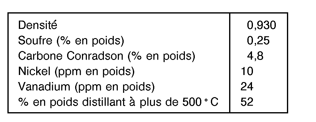
On utilise, pour le craquage, un catalyseur commercial, comprenant des zéolithes de grands stabilité et une matrice propre à craquer les molécules d'hydrocarbures les plus lourdes dans des conditions de craquage.A commercial catalyst is used for cracking, comprising zeolites with high stability and a matrix capable of cracking the heaviest hydrocarbon molecules under cracking conditions.
Deux essais ont été effectués avec la même charge. l'un dans des conditions usuelles de craquage, l'autre avec injection à mi-hauteur de l'élévateur d'un fluide de trempe constituée par de l'eau liquide.Two tests were carried out with the same load. one under usual cracking conditions, the other with injection halfway up the elevator of a quenching fluid consisting of liquid water.
Les conditions des deux essais ont été les suivantes:

Le tableau ci-dessus montre l'avantage résultant d'une élévation de la température initiale de craquage à plus de 550 °C et d'une trempe des produits de la réaction, à l'aide de l'eau, pour ramener la température du mélange à 525 ° C.The table above shows the advantage resulting from raising the initial cracking temperature above 550 ° C. and quenching the reaction products, using water, to bring the temperature down. of the mixture at 525 ° C.
Pour une température finale de craquage identique (525 °C) et du fait de la température d'injection (595 ° C au lieu de 578 ° C), la teneur en hydrogène du coke est plus faible dans le cas du procédé selon l'invention et le A coke est légèrement inférieur, ce qui montre que les fractions lourdes ont été efficacement craquées et ne restent pas adsorbées sur le catalyseur usé.For an identical final cracking temperature (525 ° C) and due to the injection temperature (595 ° C instead of 578 ° C), the hydrogen content of the coke is lower in the case of the process according to invention and the A coke is slightly lower, which shows that the heavy fractions have been effectively cracked and do not remain adsorbed on the spent catalyst.
On voit ici qu'avec une température plus basse pour le catalyseur usé et avec un A coke et une teneur en hydrogène plus faibles, il est possible d'abaisser la température finale de régénération du catalyseur d'environ 53 ° C. Ceci peut être mis à profit pour augmenter soit le rapport C/O (cas de cet exemple), soit la température de la charge, ce qui améliore de façon notable la vaporisation de la charge.We see here that with a lower temperature for the spent catalyst and with a lower A coke and a lower hydrogen content, it is possible to lower the final regeneration temperature of the catalyst by about 53 ° C. This can be used to increase either the C / O ratio (case of this example), or the temperature of the load, which significantly improves the vaporization of the load.
Les effets bénéfiques obtenus par le procédé conforme à l'invention sont résumés ci-après:
- On retiendra, essentiellement, une conversion améliorée, une meilleure sélectivité en essence et en distillat, et une production plus faible de gaz secs traduisant une réduction du craquage thermique, et de l'effet du nickel. Par ailleurs, le caractère plus oléfinique et moins aromatique des produits se traduit par un meilleur indice d'octane et un meilleur indice de cétane. Eifin, une meilleure stabilite de catalyseur, due à une température de régénération moins élevée, permet d'en réduire le taux de renouvellement pour maintenir l'activité désirée.
- We will retain, essentially, an improved conversion, a better selectivity in gasoline and in distillate, and a lower production of dry gases translating a reduction of thermal cracking, and of the effect of nickel. In addition, the more olefinic and less aromatic nature of the products results in a better octane number and a better cetane number. Eifin, better catalyst stability, due to a lower regeneration temperature, makes it possible to reduce the renewal rate to maintain the desired activity.
Le même dispositif et le même catalyseur de craquage que dans l'exemple précédent sont utilisés avec une charge dont les catactéristiques sont les suivantes:

Le fluide auxiliaire est constitué cette fois d'un recycle des effluents de craquage de point d'ébullition compris entre 340 ° C et 460 ° C, pratiqué 0,2 secondes après injection de la charge dans la zone de mélange.The auxiliary fluid this time consists of a recycling of cracking effluents with a boiling point of between 340 ° C. and 460 ° C., carried out 0.2 seconds after injection of the charge into the mixing zone.
Les conditions opératoires sont les suivantes:
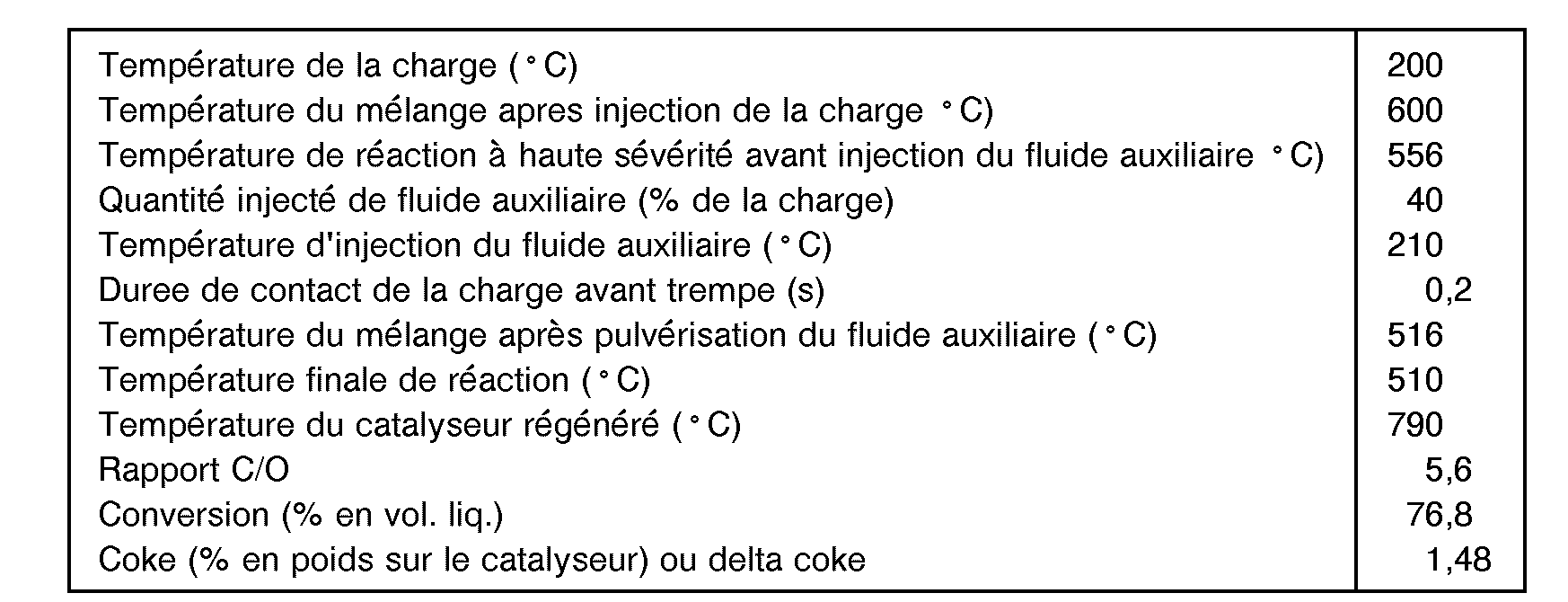
Dans cet exemple, la charge lourde considérée n'aurait pu être traités sans recourir aux moyens mis en oeuvre dans la présente invention, dans la mesure où, selon l'art antérieur, au moins 15% en poids de cette charge n'auraient pu être vaporisés, ce qui aurait conduité à une production de coke hors des limites compatibles avec la satisfaction du bilan thermique de l'unité. La température de mélange a été augmentée d'environ 40 ° C pour assurer la vaporisation complète et les conditions de choc thermique nécessaires au craquage des composés les plus lourds présents dans cette charge, après quoi la pulverisation d'un hydrocarbure dans le milieu réactionnel permet de ramener la temperature finale à 510 ° C et d'assurer ainsi une conversion optimale.In this example, the heavy load considered could not have been treated without resorting to the means used in the present invention, insofar as, according to the prior art, at least 15% by weight of this load could not have been be vaporized, which would have led to a production of coke outside the limits compatible with the satisfaction of the thermal balance of the unit. The mixing temperature was increased by approximately 40 ° C to ensure complete vaporization and the thermal shock conditions necessary for cracking the heaviest compounds present in this charge, after which the spraying of a hydrocarbon in the reaction medium allows reduce the final temperature to 510 ° C and thus ensure optimal conversion.
Le procédé conforme à l'invention permet donc d'améliorer les performances d'une unité de craquage pour une charge déterminée d'hydrocarbures. Il peut être utilisé avantage, sement pour traiter avec une plus grande efficacité ces charges plus lourdes et plus contaminées. De même, ce procédé présente un attrait exceptionnel pour le traitement de charges azotées, du riches en composés polaires (résines, asphaltènes), où la forte présence d'azote aromatique est responsable d'une chute spectaculaire de la conversion. Sur un résidu Nigerian KOLE, par exemple, le gain de conversion avec le procédé conforme à l'invention est de l'ordre de 5,5% an volume. Ceci s' explique par la plus haute température de mélange, qui déplace favorablement l'équilibre d'adsorption de l'azote aromatique, en réduisant ainsi la neutralisation de certains sites acides du catalyseur.The process according to the invention therefore makes it possible to improve the performance of a cracking unit for a determined charge of hydrocarbons. It can advantageously be used to treat these heavier and more contaminated loads with greater efficiency. Likewise, this process has an exceptional appeal for the treatment of nitrogenous charges, rich in polar compounds (resins, asphaltenes), where the strong presence of aromatic nitrogen is responsible for a spectacular drop in conversion. On a Nigerian KOLE residue, for example, the conversion gain with the process according to the invention is around 5.5% by volume. This is explained by the higher mixing temperature, which favorably displaces the adsorption balance of the aromatic nitrogen, thereby reducing the neutralization of certain acid sites of the catalyst.
Claims (6)
Applications Claiming Priority (2)
| Application Number | Priority Date | Filing Date | Title |
|---|---|---|---|
| FR8510569 | 1985-07-10 | ||
| FR8510569A FR2584732B1 (en) | 1985-07-10 | 1985-07-10 | PROCESS AND DEVICE FOR THE CATALYTIC CRACKING OF HYDROCARBON CHARGES, WITH CONTROL OF THE REACTION TEMPERATURE |
Publications (3)
| Publication Number | Publication Date |
|---|---|
| EP0208609A1 EP0208609A1 (en) | 1987-01-14 |
| EP0208609B1 EP0208609B1 (en) | 1989-06-14 |
| EP0208609B2 true EP0208609B2 (en) | 1995-08-16 |
Family
ID=9321160
Family Applications (1)
| Application Number | Title | Priority Date | Filing Date |
|---|---|---|---|
| EP86401464A Expired - Lifetime EP0208609B2 (en) | 1985-07-10 | 1986-07-02 | Process and apparatus for the catalytic cracking of hydrocarbons, with control of the reaction temperature |
Country Status (9)
| Country | Link |
|---|---|
| US (1) | US4818372A (en) |
| EP (1) | EP0208609B2 (en) |
| CN (1) | CN1015374B (en) |
| AR (1) | AR240172A1 (en) |
| AU (1) | AU585035B2 (en) |
| CA (1) | CA1272974A (en) |
| DE (1) | DE3663953D1 (en) |
| FR (1) | FR2584732B1 (en) |
| ZA (1) | ZA865183B (en) |
Families Citing this family (40)
| Publication number | Priority date | Publication date | Assignee | Title |
|---|---|---|---|---|
| US4978440A (en) * | 1984-10-30 | 1990-12-18 | Mobil Oil Corporation | Quenched catalytic cracking process |
| FR2605643B1 (en) * | 1986-10-24 | 1989-08-18 | Total France | METHOD AND DEVICE FOR CATALYTIC CRACKING IN A FLUIDIZED BED OF A HYDROCARBON LOAD |
| IN168767B (en) * | 1987-06-02 | 1991-06-01 | Int Control Automation Finance | |
| US5000924A (en) * | 1987-06-02 | 1991-03-19 | Elsagainternational B.V. | Autoacceleration control for exothermic reactors |
| EP0311375A1 (en) * | 1987-10-08 | 1989-04-12 | Mobil Oil Corporation | Process for cracking a hydrocarbon feedstock to obtain gasoline and olefins and upgrading the olefins to improve the total gasoline yield |
| FR2624762B1 (en) * | 1987-12-21 | 1990-06-08 | Total France | METHOD AND DEVICE FOR REGENERATING A FLUIDIZED BED CATALYST |
| US5264115A (en) * | 1987-12-30 | 1993-11-23 | Compagnie De Raffinage Et De Distribution Total France | Process and apparatus for fluidized bed hydrocarbon conversion |
| FR2625509B1 (en) * | 1987-12-30 | 1990-06-22 | Total France | METHOD AND DEVICE FOR CONVERTING HYDROCARBONS INTO A FLUIDIZED BED |
| US5271826A (en) * | 1988-03-03 | 1993-12-21 | Mobil Oil Corporation | Catalytic cracking of coke producing hydrocarbons |
| US5087349A (en) * | 1988-11-18 | 1992-02-11 | Stone & Webster Engineering Corporation | Process for selectively maximizing product production in fluidized catalytic cracking of hydrocarbons |
| DE68914291T2 (en) * | 1989-09-01 | 1994-09-01 | Total Raffinage Distribution | METHOD AND DEVICE FOR VAPOR CRACKING HYDROCARBONS IN THE FLUIDIZED STAGE. |
| FR2655053B1 (en) * | 1989-11-24 | 1994-04-29 | Inst Francais Du Petrole | METHOD AND DEVICE FOR REGULATING THE OPERATING CONDITIONS OF A CATALYTIC CRACKING REACTOR USING A SOURCE OF IONIZING RADIATION. |
| CA2035933A1 (en) * | 1990-02-27 | 1991-08-28 | Exxon Research And Engineering Company | Fluid catalytic cracking unit and process comprising an improved feed injection system |
| CA2036067A1 (en) * | 1990-02-27 | 1991-08-28 | Exxon Research And Engineering Company | Process and apparatus for controlling a fluid catalytic cracking unit |
| CA2043454A1 (en) * | 1990-07-03 | 1992-01-04 | Exxon Research & Engineering Company | Fluid hydrocarbon conversion and cracking apparatus and process comprising a novel feed injection system |
| CA2044074C (en) * | 1990-07-03 | 2003-01-21 | Craig Y. Sabottke | Controlling temperature, yields and selectivity in a fluid hydrocarbon conversion and cracking apparatus and process comprising a novel feed injection system |
| WO1993022402A1 (en) * | 1992-05-04 | 1993-11-11 | Mobil Oil Corporation | Catalytic cracking of distilled feeds |
| CA2130816C (en) * | 1992-05-04 | 2004-03-16 | Yusuf G. Adewuyi | Fluidized catalytic cracking |
| US5954942A (en) * | 1992-05-04 | 1999-09-21 | Mobil Oil Corporation | Catalytic cracking with delayed quench |
| US5389232A (en) * | 1992-05-04 | 1995-02-14 | Mobil Oil Corporation | Riser cracking for maximum C3 and C4 olefin yields |
| FR2770225B1 (en) * | 1997-10-24 | 2000-01-07 | Total Raffinage Distribution | METHOD AND DEVICE FOR SELECTIVE VAPORIZATION OF HYDROCARBON LOADS IN CATALYTIC CRACKING |
| EP1046696B1 (en) * | 1999-04-23 | 2014-06-11 | China Petrochemical Corporation | A catalytic conversion process for producing isobutane and isoparaffin-enriched gasoline |
| US7169293B2 (en) * | 1999-08-20 | 2007-01-30 | Uop Llc | Controllable space velocity reactor and process |
| US20040104149A1 (en) * | 1999-08-20 | 2004-06-03 | Lomas David A. | Controllable volume reactor and process |
| CN1090530C (en) * | 2000-04-28 | 2002-09-11 | 清华大学 | Catalyst inlet device adaptable to gas-solid cocurrent flow descending bed reactor |
| US7351326B1 (en) | 2002-07-23 | 2008-04-01 | Hartley Owen | FCC closed cyclone with snorkel |
| BR0205585A (en) * | 2002-10-29 | 2004-08-03 | Petroleo Brasileiro Sa | Fluid catalytic cracking process for high basic nitrogen hydrocarbon fillers |
| CN1819870B (en) * | 2002-12-20 | 2010-12-08 | 环球油品公司 | Fluidized-bed reactor with residence time control |
| WO2004058388A2 (en) * | 2002-12-20 | 2004-07-15 | Uop Llc | Fluidized bed reactor with residence time control |
| BR0302326A (en) * | 2003-06-03 | 2005-03-29 | Petroleo Brasileiro Sa | Fluid catalytic cracking process of mixed hydrocarbon fillers from different sources |
| FR2877671B1 (en) | 2004-11-09 | 2008-10-17 | Inst Francais Du Petrole | DEVICE AND METHOD FOR CATALYTIC CRACKING OF TWO SEPARATE HYDROCARBON LOADS |
| BRPI0504854A (en) * | 2005-10-31 | 2007-09-18 | Petroleo Brasileiro Sa | fcc process for maximizing middle distillates |
| FR2894849B1 (en) * | 2005-12-20 | 2008-05-16 | Inst Francais Du Petrole | NEW REACTOR WITH TWO REACTIONAL ZONES FLUIDIZED WITH INTEGRATED GAS / SOLID SEPARATION SYSTEM |
| FR2894848B1 (en) * | 2005-12-21 | 2008-02-22 | Inst Francais Du Petrole | CATALYST REDISTRIBUTION DEVICE IN FCC RISERS |
| JP2007258481A (en) * | 2006-03-23 | 2007-10-04 | Fujitsu Ltd | Semiconductor device and its manufacturing method |
| BRPI0605327B1 (en) * | 2006-12-20 | 2016-12-20 | Petroleo Brasileiro Sa | fluidized bed catalytic cracking process of petroleum hydrocarbon streams with maximization of light olefin production |
| BRPI0800236B1 (en) | 2008-01-24 | 2019-05-14 | Petroleo Brasileiro S.A. - Petrobras | FLUID CATALYTIC CRACKING PROCESS AND EQUIPMENT FOR THE PRODUCTION OF LOW AROMATIC MEDIUM DISTILLED |
| US20090299119A1 (en) * | 2008-05-29 | 2009-12-03 | Kellogg Brown & Root Llc | Heat Balanced FCC For Light Hydrocarbon Feeds |
| US8057641B2 (en) * | 2010-07-19 | 2011-11-15 | Kior Inc. | Method and apparatus for pyrolysis of a biomass |
| WO2024050000A1 (en) * | 2022-08-31 | 2024-03-07 | T.En Process Technology, Inc. | Systems and processes for residence time control in downer reactors |
Family Cites Families (19)
| Publication number | Priority date | Publication date | Assignee | Title |
|---|---|---|---|---|
| US2685498A (en) * | 1948-12-30 | 1954-08-03 | Kellogg M W Co | Method for controlling thermal conditions in a gaseous reaction |
| US3053753A (en) * | 1959-10-16 | 1962-09-11 | Kellogg M W Co | Hydrocarbon conversion apparatus and method of operation |
| US3617497A (en) * | 1969-06-25 | 1971-11-02 | Gulf Research Development Co | Fluid catalytic cracking process with a segregated feed charged to the reactor |
| US3692667A (en) * | 1969-11-12 | 1972-09-19 | Gulf Research Development Co | Catalytic cracking plant and method |
| US3886060A (en) * | 1973-04-30 | 1975-05-27 | Mobil Oil Corp | Method for catalytic cracking of residual oils |
| US3894936A (en) * | 1973-11-19 | 1975-07-15 | Mobil Oil Corp | Conversion of hydrocarbons with {37 Y{38 {0 faujasite-type catalysts |
| US3896024A (en) * | 1974-04-02 | 1975-07-22 | Mobil Oil Corp | Process for producing light fuel oil |
| US4026789A (en) * | 1975-01-17 | 1977-05-31 | Phillips Petroleum Company | Method for catalytically cracking hydrocarbons |
| US3984936A (en) * | 1975-04-30 | 1976-10-12 | Russell John Camp | Disposable animal trap |
| US4088568A (en) * | 1976-01-15 | 1978-05-09 | Mobil Oil Corporation | Catalytic cracking of hydrocarbons |
| US4283273A (en) * | 1976-11-18 | 1981-08-11 | Mobil Oil Corporation | Method and system for regenerating fluidizable catalyst particles |
| US4446009A (en) * | 1980-06-02 | 1984-05-01 | Engelhard Corporation | Selective vaporization process and apparatus |
| US4411773A (en) * | 1980-12-18 | 1983-10-25 | Mobil Oil Corporation | Heat balance in FCC process and apparatus with downflow reactor riser |
| US4450241A (en) * | 1981-08-05 | 1984-05-22 | Ashland Oil, Inc. | Endothermic removal of coke deposited on catalytic materials during carbo-metallic oil conversion |
| US4422925A (en) * | 1981-12-28 | 1983-12-27 | Texaco Inc. | Catalytic cracking |
| US4427537A (en) * | 1982-03-17 | 1984-01-24 | Dean Robert R | Method and means for preparing and dispersing atomed hydrocarbon with fluid catalyst particles in a reactor zone |
| US4435279A (en) * | 1982-08-19 | 1984-03-06 | Ashland Oil, Inc. | Method and apparatus for converting oil feeds |
| US4437977A (en) * | 1982-09-29 | 1984-03-20 | Phillips Petroleum Company | Control of a catalytic cracking unit |
| US4588558A (en) * | 1983-09-06 | 1986-05-13 | Mobil Oil Corporation | Closed FCC cyclone system |
-
1985
- 1985-07-10 FR FR8510569A patent/FR2584732B1/en not_active Expired
-
1986
- 1986-07-02 EP EP86401464A patent/EP0208609B2/en not_active Expired - Lifetime
- 1986-07-02 DE DE8686401464T patent/DE3663953D1/en not_active Expired
- 1986-07-09 CA CA000513414A patent/CA1272974A/en not_active Expired - Fee Related
- 1986-07-09 AU AU59881/86A patent/AU585035B2/en not_active Ceased
- 1986-07-09 CN CN86104812A patent/CN1015374B/en not_active Expired
- 1986-07-10 ZA ZA865183A patent/ZA865183B/en unknown
- 1986-07-10 AR AR304481A patent/AR240172A1/en active
-
1987
- 1987-10-20 US US07/111,115 patent/US4818372A/en not_active Expired - Lifetime
Also Published As
| Publication number | Publication date |
|---|---|
| CN1015374B (en) | 1992-02-05 |
| EP0208609A1 (en) | 1987-01-14 |
| US4818372A (en) | 1989-04-04 |
| AR240172A1 (en) | 1990-02-28 |
| EP0208609B1 (en) | 1989-06-14 |
| AU5988186A (en) | 1987-01-15 |
| DE3663953D1 (en) | 1989-07-20 |
| ZA865183B (en) | 1987-03-25 |
| FR2584732B1 (en) | 1988-08-19 |
| AU585035B2 (en) | 1989-06-08 |
| FR2584732A1 (en) | 1987-01-16 |
| CA1272974A (en) | 1990-08-21 |
| CN86104812A (en) | 1987-01-07 |
Similar Documents
| Publication | Publication Date | Title |
|---|---|---|
| EP0208609B2 (en) | Process and apparatus for the catalytic cracking of hydrocarbons, with control of the reaction temperature | |
| EP0479645B1 (en) | Process and apparatus for the fluid catalytic cracking with downflow | |
| EP0323297B1 (en) | Fluidised bed hydrocarbon conversion process | |
| EP0191695B1 (en) | Process and apparatus for the injection of a catalyst into a fluid catalytic cracking process, especially of heavy feeds | |
| EP0171330B1 (en) | Process and apparatus for catalytic fluidised cracking | |
| EP0184517B1 (en) | Hydrocarbon feed catalytic cracking processes and apparatuses | |
| EP0485259B1 (en) | Process and apparatus for homogenisation in a tubular hydrocarbon cracking reactor with fluid solid particles, of the mixture of these particles and the hydrocarbon gases to be treated | |
| FR2811327A1 (en) | HYDROCARBON CRACKING METHOD AND DEVICE IMPLEMENTING TWO SUCCESSIVE REACTIONAL CHAMBERS | |
| EP0489726B1 (en) | Method and device for vapor-cracking of hydrocarbons in fluidized phase | |
| FR2659346A1 (en) | CRACKING PROCESS WITH OLIGOMERIZATION OR TRIMERIZATION OF OLEFINS PRESENT IN EFFLUENTS. | |
| EP0874880B1 (en) | Method and device for fluid catalytic cracking of hydrocarbon feedstock | |
| FR2610638A1 (en) | IMPROVEMENTS IN PROCESSES AND DEVICES FOR CATALYTIC CRACKING OF HYDROCARBON LOADS | |
| EP0291408B1 (en) | Steam cracking process in a fluidised-bed reaction zone | |
| EP0573316B1 (en) | Process and apparatus for the catalytic cracking in two successive reaction zones | |
| EP0911379A1 (en) | Process and apparatus for the selective vaporisation of hydrocarbon feeds in catalytic cracking | |
| EP0265347A1 (en) | Process and apparatus for the fluidised catalytic cracking of a hydrocarbon feed | |
| FR2682119A1 (en) | IMPROVEMENTS IN CATALYTIC CRACKING DEVICES IN THE FLUID CONDITION OF HYDROCARBON LOADS. | |
| EP0322276A1 (en) | Heavy charge catalytic cracking process and apparatus comprising a second stripping in a fluidised bed | |
| FR2658833A1 (en) | Process for cracking a hydrocarbon feedstock in the fluid state | |
| FR2521157A1 (en) | Fluidised catalytic cracking of distillate gas oil - with supplemental feed of decarbonised residual fraction | |
| BE892090A (en) | PREPARATION OF A FLUID CATALYTIC CRACKING LOAD BY SELECTIVE VAPORIZATION | |
| FR2628436A1 (en) | Fluidised bed high temp. vapour cracking - useful for prodn. of olefin(s) | |
| WO1991003527A1 (en) | Method and device for vapor-cracking of hydrocarbons in fluidized phase | |
| LU84039A1 (en) | SELECTIVE VAPORIZATION METHOD AND APPARATUS | |
| FR2659976A1 (en) | CATALYTIC CRACKING WITH BRUSH COOLING. |
Legal Events
| Date | Code | Title | Description |
|---|---|---|---|
| PUAI | Public reference made under article 153(3) epc to a published international application that has entered the european phase |
Free format text: ORIGINAL CODE: 0009012 |
|
| AK | Designated contracting states |
Kind code of ref document: A1 Designated state(s): BE CH DE FR GB IT LI LU NL |
|
| 17P | Request for examination filed |
Effective date: 19870615 |
|
| 17Q | First examination report despatched |
Effective date: 19880715 |
|
| GRAA | (expected) grant |
Free format text: ORIGINAL CODE: 0009210 |
|
| AK | Designated contracting states |
Kind code of ref document: B1 Designated state(s): BE CH DE FR GB IT LI LU NL |
|
| ITF | It: translation for a ep patent filed |
Owner name: BARZANO' E ZANARDO MILANO S.P.A. |
|
| REF | Corresponds to: |
Ref document number: 3663953 Country of ref document: DE Date of ref document: 19890720 |
|
| GBT | Gb: translation of ep patent filed (gb section 77(6)(a)/1977) | ||
| PLBI | Opposition filed |
Free format text: ORIGINAL CODE: 0009260 |
|
| 26 | Opposition filed |
Opponent name: MOBIL OIL CORPORATION Effective date: 19900313 |
|
| NLR1 | Nl: opposition has been filed with the epo |
Opponent name: MOBIL OIL CORPORATION. |
|
| PGFP | Annual fee paid to national office [announced via postgrant information from national office to epo] |
Ref country code: LU Payment date: 19910703 Year of fee payment: 6 |
|
| PGFP | Annual fee paid to national office [announced via postgrant information from national office to epo] |
Ref country code: BE Payment date: 19910710 Year of fee payment: 6 |
|
| ITTA | It: last paid annual fee | ||
| PGFP | Annual fee paid to national office [announced via postgrant information from national office to epo] |
Ref country code: NL Payment date: 19910731 Year of fee payment: 6 Ref country code: CH Payment date: 19910731 Year of fee payment: 6 |
|
| EPTA | Lu: last paid annual fee | ||
| PG25 | Lapsed in a contracting state [announced via postgrant information from national office to epo] |
Ref country code: LU Free format text: LAPSE BECAUSE OF NON-PAYMENT OF DUE FEES Effective date: 19920702 |
|
| PG25 | Lapsed in a contracting state [announced via postgrant information from national office to epo] |
Ref country code: LI Effective date: 19920731 Ref country code: CH Effective date: 19920731 Ref country code: BE Effective date: 19920731 |
|
| BERE | Be: lapsed |
Owner name: CIE DE RAFFINAGE ET DE DISTRIBUTION TOTAL FRANCE Effective date: 19920731 |
|
| PG25 | Lapsed in a contracting state [announced via postgrant information from national office to epo] |
Ref country code: NL Effective date: 19930201 |
|
| NLV4 | Nl: lapsed or anulled due to non-payment of the annual fee | ||
| REG | Reference to a national code |
Ref country code: CH Ref legal event code: PL |
|
| PUAH | Patent maintained in amended form |
Free format text: ORIGINAL CODE: 0009272 |
|
| STAA | Information on the status of an ep patent application or granted ep patent |
Free format text: STATUS: PATENT MAINTAINED AS AMENDED |
|
| RAP2 | Party data changed (patent owner data changed or rights of a patent transferred) |
Owner name: TOTAL RAFFINAGE DISTRIBUTION S.A. |
|
| 27A | Patent maintained in amended form |
Effective date: 19950816 |
|
| AK | Designated contracting states |
Kind code of ref document: B2 Designated state(s): BE CH DE FR GB IT LI LU NL |
|
| GBTA | Gb: translation of amended ep patent filed (gb section 77(6)(b)/1977) |
Effective date: 19950816 |
|
| APAC | Appeal dossier modified |
Free format text: ORIGINAL CODE: EPIDOS NOAPO |
|
| APAC | Appeal dossier modified |
Free format text: ORIGINAL CODE: EPIDOS NOAPO |
|
| REG | Reference to a national code |
Ref country code: GB Ref legal event code: IF02 |
|
| PGFP | Annual fee paid to national office [announced via postgrant information from national office to epo] |
Ref country code: GB Payment date: 20050627 Year of fee payment: 20 |
|
| PG25 | Lapsed in a contracting state [announced via postgrant information from national office to epo] |
Ref country code: IT Free format text: LAPSE BECAUSE OF NON-PAYMENT OF DUE FEES;WARNING: LAPSES OF ITALIAN PATENTS WITH EFFECTIVE DATE BEFORE 2007 MAY HAVE OCCURRED AT ANY TIME BEFORE 2007. THE CORRECT EFFECTIVE DATE MAY BE DIFFERENT FROM THE ONE RECORDED. Effective date: 20050702 |
|
| PGFP | Annual fee paid to national office [announced via postgrant information from national office to epo] |
Ref country code: DE Payment date: 20050714 Year of fee payment: 20 |
|
| PGFP | Annual fee paid to national office [announced via postgrant information from national office to epo] |
Ref country code: FR Payment date: 20050728 Year of fee payment: 20 |
|
| APAH | Appeal reference modified |
Free format text: ORIGINAL CODE: EPIDOSCREFNO |
|
| PG25 | Lapsed in a contracting state [announced via postgrant information from national office to epo] |
Ref country code: GB Free format text: LAPSE BECAUSE OF EXPIRATION OF PROTECTION Effective date: 20060701 |
|
| REG | Reference to a national code |
Ref country code: GB Ref legal event code: PE20 |