EP0208574A1 - Dipped headlamp for a motor vehicle - Google Patents
Dipped headlamp for a motor vehicle Download PDFInfo
- Publication number
- EP0208574A1 EP0208574A1 EP86401216A EP86401216A EP0208574A1 EP 0208574 A1 EP0208574 A1 EP 0208574A1 EP 86401216 A EP86401216 A EP 86401216A EP 86401216 A EP86401216 A EP 86401216A EP 0208574 A1 EP0208574 A1 EP 0208574A1
- Authority
- EP
- European Patent Office
- Prior art keywords
- filament
- reflector
- horizontal
- lamp
- images
- Prior art date
- Legal status (The legal status is an assumption and is not a legal conclusion. Google has not performed a legal analysis and makes no representation as to the accuracy of the status listed.)
- Granted
Links
Images


Classifications
-
- F—MECHANICAL ENGINEERING; LIGHTING; HEATING; WEAPONS; BLASTING
- F21—LIGHTING
- F21S—NON-PORTABLE LIGHTING DEVICES; SYSTEMS THEREOF; VEHICLE LIGHTING DEVICES SPECIALLY ADAPTED FOR VEHICLE EXTERIORS
- F21S41/00—Illuminating devices specially adapted for vehicle exteriors, e.g. headlamps
- F21S41/30—Illuminating devices specially adapted for vehicle exteriors, e.g. headlamps characterised by reflectors
- F21S41/32—Optical layout thereof
- F21S41/33—Multi-surface reflectors, e.g. reflectors with facets or reflectors with portions of different curvature
- F21S41/331—Multi-surface reflectors, e.g. reflectors with facets or reflectors with portions of different curvature the reflector consisting of complete annular areas
- F21S41/332—Multi-surface reflectors, e.g. reflectors with facets or reflectors with portions of different curvature the reflector consisting of complete annular areas with continuity at the junction between adjacent areas
-
- F—MECHANICAL ENGINEERING; LIGHTING; HEATING; WEAPONS; BLASTING
- F21—LIGHTING
- F21S—NON-PORTABLE LIGHTING DEVICES; SYSTEMS THEREOF; VEHICLE LIGHTING DEVICES SPECIALLY ADAPTED FOR VEHICLE EXTERIORS
- F21S41/00—Illuminating devices specially adapted for vehicle exteriors, e.g. headlamps
-
- F—MECHANICAL ENGINEERING; LIGHTING; HEATING; WEAPONS; BLASTING
- F21—LIGHTING
- F21S—NON-PORTABLE LIGHTING DEVICES; SYSTEMS THEREOF; VEHICLE LIGHTING DEVICES SPECIALLY ADAPTED FOR VEHICLE EXTERIORS
- F21S41/00—Illuminating devices specially adapted for vehicle exteriors, e.g. headlamps
- F21S41/10—Illuminating devices specially adapted for vehicle exteriors, e.g. headlamps characterised by the light source
- F21S41/14—Illuminating devices specially adapted for vehicle exteriors, e.g. headlamps characterised by the light source characterised by the type of light source
- F21S41/162—Incandescent light sources, e.g. filament or halogen lamps
- F21S41/166—Incandescent light sources, e.g. filament or halogen lamps characterised by the shape of the filament
-
- F—MECHANICAL ENGINEERING; LIGHTING; HEATING; WEAPONS; BLASTING
- F21—LIGHTING
- F21S—NON-PORTABLE LIGHTING DEVICES; SYSTEMS THEREOF; VEHICLE LIGHTING DEVICES SPECIALLY ADAPTED FOR VEHICLE EXTERIORS
- F21S41/00—Illuminating devices specially adapted for vehicle exteriors, e.g. headlamps
- F21S41/20—Illuminating devices specially adapted for vehicle exteriors, e.g. headlamps characterised by refractors, transparent cover plates, light guides or filters
- F21S41/28—Cover glass
-
- F—MECHANICAL ENGINEERING; LIGHTING; HEATING; WEAPONS; BLASTING
- F21—LIGHTING
- F21S—NON-PORTABLE LIGHTING DEVICES; SYSTEMS THEREOF; VEHICLE LIGHTING DEVICES SPECIALLY ADAPTED FOR VEHICLE EXTERIORS
- F21S41/00—Illuminating devices specially adapted for vehicle exteriors, e.g. headlamps
- F21S41/30—Illuminating devices specially adapted for vehicle exteriors, e.g. headlamps characterised by reflectors
- F21S41/32—Optical layout thereof
- F21S41/321—Optical layout thereof the reflector being a surface of revolution or a planar surface, e.g. truncated
-
- F—MECHANICAL ENGINEERING; LIGHTING; HEATING; WEAPONS; BLASTING
- F21—LIGHTING
- F21S—NON-PORTABLE LIGHTING DEVICES; SYSTEMS THEREOF; VEHICLE LIGHTING DEVICES SPECIALLY ADAPTED FOR VEHICLE EXTERIORS
- F21S41/00—Illuminating devices specially adapted for vehicle exteriors, e.g. headlamps
- F21S41/30—Illuminating devices specially adapted for vehicle exteriors, e.g. headlamps characterised by reflectors
- F21S41/32—Optical layout thereof
- F21S41/323—Optical layout thereof the reflector having two perpendicular cross sections having regular geometrical curves of a distinct nature
-
- F—MECHANICAL ENGINEERING; LIGHTING; HEATING; WEAPONS; BLASTING
- F21—LIGHTING
- F21S—NON-PORTABLE LIGHTING DEVICES; SYSTEMS THEREOF; VEHICLE LIGHTING DEVICES SPECIALLY ADAPTED FOR VEHICLE EXTERIORS
- F21S41/00—Illuminating devices specially adapted for vehicle exteriors, e.g. headlamps
- F21S41/30—Illuminating devices specially adapted for vehicle exteriors, e.g. headlamps characterised by reflectors
- F21S41/32—Optical layout thereof
- F21S41/33—Multi-surface reflectors, e.g. reflectors with facets or reflectors with portions of different curvature
-
- F—MECHANICAL ENGINEERING; LIGHTING; HEATING; WEAPONS; BLASTING
- F21—LIGHTING
- F21S—NON-PORTABLE LIGHTING DEVICES; SYSTEMS THEREOF; VEHICLE LIGHTING DEVICES SPECIALLY ADAPTED FOR VEHICLE EXTERIORS
- F21S41/00—Illuminating devices specially adapted for vehicle exteriors, e.g. headlamps
- F21S41/40—Illuminating devices specially adapted for vehicle exteriors, e.g. headlamps characterised by screens, non-reflecting members, light-shielding members or fixed shades
Definitions
- the present invention relates to a dipped headlight for a motor vehicle, in which the light beam is cut above two horizontal half-planes offset in height.
- contour of the cut is defined by two horizontal half-lines, the half-line on the right side being at the level of the horizontal and the half-line on the left side being offset by about 1.5% in below the horizontal.
- the beams meeting these standards are most often designed with a projector provided with a transverse filament lamp cooperating with a parabolic mirror of relatively large focal length, so as to reduce the thickness of the beam and consequently minimize the extra thicknesses due to prisms deflectors on the closing glass.
- One of the aims of the invention is to propose a dipped headlight overcoming the aforementioned drawbacks and allowing maximum recovery of the luminous flux emitted by the filament of the lamp.
- the proposed low-beam headlamp comprises, in a conventional manner, a lamp, a reflector and a closing glass placed in front of the reflector, as well as means for cutting the light beam above two horizontal half-planes offset in height.
- the mirror is preferably inclined downwards from the angle which characterizes the angular spacing of the left cut of the beam USA relative to the horizontal so as to initiate the left cut. It is also inclined to the right by an angle corresponding approximately to the angular half-width of the concentration images coming from the edges of the mirror, concentration images which are raised to the level of the horizontal with the ice.
- the correcting means comprise two lateral surfaces adjoining the deflecting surface, with the same equation as an extension of the latter, except for an upward tilting, the distribution glass then being slightly deviating towards vertical.
- the deflecting surface is a surface capable of forming images of the filament each having their highest point situated on a horizontal line.
- the projector according to the invention shown schematically in Figure 1, comprises a reflector 10, an axial filament lamp 20, and a distribution glass 30 closing the projector.
- the surface of the reflector is a surface without discontinuity, chosen so as to form images of the filament all of whose points are situated below a horizontal plane - advantageously, all these images having their highest point aligned on this horizontal plane .
- absence of discontinuity is meant a second order continuity guaranteed at any point on the surface, that is to say that the radius of curvature and the position of the center of curvature always vary continuously; this arrangement makes it possible, in practice, to produce real surfaces having a very good conformity with the theoretical surfaces, thus avoiding the defects which were specific to the system with “offset paraboloids” described above: continuity at second order in particular makes the reflector perfectly stampable in principle.
- the distance separating, in the radial direction, the surface of the reflector from the surface defined by the equation does not exceed 0.15 mm.
- the normal difference separating, in the vertical plane passing through the origin of the coordinates, the trace of the surface of the reflector of the corresponding least-square parabola does not exceed 0.3 mm (the concept of "parabola least squares "is explained in the two aforementioned documents).
- the distance from the emissive surface to the axis does not exceed 25% of the diameter of the filament, in one direction or the other.
- the axial centering of the filament relative to the point of coordinates (f 0 o, o) is carried out with a tolerance of 10% of the length of the filament, in one direction or the other.
- Figures 4 to 11 and Figure 12 show the illumination provided by regions 12 to 16 and 11, respectively, of the bare reflector thus defined, with a horizontal axis Ox.
- the regions 12 'to 19' produce an illumination symmetrical with respect to the vertical vv 'of the illuminations produced by the regions 12 to 19, respectively.
- the outermost curve corresponds to an illumination of 100 candelas
- the next curve to an illumination of 1000 candelas
- the other curves to increasing illuminations of 2000, 4000, .... candelas.
- the filament-reflector assembly is tilted down and to the right towards the concentration point. maximum as defined by standard SAE J 579 c, as indicated above.
- these correcting means consist of prisms formed on the homologous regions 30b and 30c of the closing glass (FIG. 3), which are provided with prisms of 1 to 3 °.
- the central region 30a of the closing glass can be striated in a conventional manner, to obtain the desired comfort and widening for the light beam.
- the surface 10a of the reflector is extended by two lateral surfaces 10b and 10c of the same equation, but slightly angularly offset (as can be seen in FIG. 15), also by an angle of l '' order from 1 to 3 °.
- the reflector of the preceding embodiment is modified (FIG. 2) while retaining the same surface equation, except that the part comprising the regions 16 to 19 is tilted very slightly upwards. on the one hand, and that comprising the regions 16 'to 19' on the other.
- the regions 30b and 30c of the closing glass can be devoid of prisms, or only very slightly prismatic, which makes it possible to eliminate the dazzling factors due to the multiplicity of horizontal drafts resulting from the presence of the prisms in the previous case.
- the projector according to the invention is capable of collecting a luminous flux much higher than that given by a paraboloid of an axial filament projector of conventional design, projector whose focal length can hardly be reduced to values less than 29 mm.
- the headlight of the invention it is possible to use a low base focal length f 0 , for example of 22.5 mm, which makes it possible for example to produce a headlight of generally rectangular, symmetrical shape, of 70 mm high and 150 mm wide.
- the gain in flow is then close to 30% compared to conventional projectors, the most common focal length of which is 31.75 mm and the height always limited to minimum values of the order of 100 mm.
Abstract
La présente invention concerne un projectuer de croisement pour véhicule automobile, du type comportant une lampe (20), un réflecteur (10) et une glace de fermeture (30) placée devant le réflecteur, ainsi que des moyens de coupure du faisceau lumineux au-dessus de deux demi-plans horizontaux décalés en hauteur. Selon l'invention : la lampe est une lampe à filament axial dépourvue de coupelle d'occultation ; le réflecteur comporte une surface déviatrice sans discontinuité propre à former des images du filament dont tour les points sont situés au-dessous d'un plan horizontal ; et il est prévu des moyens correcteurs propres à déplacer angulairement ces images vers le haut pour les ramener au niveau des deux demi-plans horizontaux de la coupure.The present invention relates to a dipped headlamp for a motor vehicle, of the type comprising a lamp (20), a reflector (10) and a closing glass (30) placed in front of the reflector, as well as means for switching off the light beam above two horizontal half-planes offset in height. According to the invention: the lamp is an axial filament lamp devoid of concealment cup; the reflector comprises a deviating surface without discontinuity suitable for forming images of the filament, the points of which all lie below a horizontal plane; and corrective means are provided capable of angularly moving these images upward to bring them back to the level of the two horizontal half-planes of the cut.
Description
La présente invention concerne un projecteur de croisement pour véhicule automobile, dans lequel le faisceau lumineux est coupé au-dessus de deux demi-plans horizontaux décalés en hauteur.The present invention relates to a dipped headlight for a motor vehicle, in which the light beam is cut above two horizontal half-planes offset in height.
Ce type de coupure, qui est notamment décrit dans le FR-A-2 087 317 (correspondant au US-A-3 858 040) est tout particulièrement adapté aux normes d'éclairement en vigueur aux U.S.A., telles qu'elles sont par exemple définies par la norme SAE J 579 C.This type of cutoff, which is described in particular in FR-A-2 087 317 (corresponding to US-A-3 858 040) is very particularly suited to the lighting standards in force in the USA, such as they are for example defined by SAE J 579 C.
Plus précisément, le contour de la coupure : est défini par deux demi-droites horizontales, la demi-droite du côté droit étant au niveau de l'horizontale et la demi-droite du côté gauche étant décalée d'environ 1,5 % en dessous de l'horizontale.More precisely, the contour of the cut: is defined by two horizontal half-lines, the half-line on the right side being at the level of the horizontal and the half-line on the left side being offset by about 1.5% in below the horizontal.
Les faisceaux répondant à ces normes sont le plus souvent conçus avec un projecteur pourvu d'une lampe à filament transversal coopérant avec un miroir parabolique de focale relativement importante, de façon à diminuer l'épaisseur du faisceau et par conséquent minimiser les surépaisseurs dues aux prismes déviateurs sur la glace de fermeture.The beams meeting these standards are most often designed with a projector provided with a transverse filament lamp cooperating with a parabolic mirror of relatively large focal length, so as to reduce the thickness of the beam and consequently minimize the extra thicknesses due to prisms deflectors on the closing glass.
Il a été également proposé des projecteurs pourvus d'une lampe à filament axial. Le filament est focalisé dans un réflecteur parabolique, incliné vers le bas pour réduire la déviation demandée aux prismes de la glace, et donc les surépaisseurs de cette dernière.Projectors have also been proposed provided with an axial filament lamp. The filament is focused in a parabolic reflector, tilted downwards to reduce the deviation required from the prisms of the ice, and therefore the thicknesses of the latter.
Le FR-A-2 087 317 précité donne des exemples de ces deux types de projecteurs.The aforementioned FR-A-2 087 317 gives examples of these two types of projectors.
Mais, dans l'un et l'autre cas, il est nécessaire d'utiliser un réflecteur parabolique de focale importante (de l'ordre de 29 à 32 mm) donc peu récupératrice de flux.However, in both cases, it is necessary to use a parabolic reflector with a large focal length (of the order of 29 to 32 mm), therefore with little flux recovery.
En effet, une focale courte produirait des images trop grandes qui ne permettraient pas de réaliser le faisceau souhaité, à moins de prévoir des prismes très fortement déviateurs au niveau de la glace de fermeture, exigence incompatible avec les nécessités pratiques du moulage (notamment pour les glaces en verre) ; en outre, des prismes fortement déviateurs ne permettent pas d'obtenir une netteté de coupure satisfaisante en raison des dispersions de lumière produites par les dépouilles très accentuées de la glace.Indeed, a short focal length would produce too large images which would not make it possible to realize the desired beam, unless there are very strongly deflecting prisms at the level of the closing glass, a requirement incompatible with the practical necessities of molding (in particular for glass glass); in addition, highly deflecting prisms do not make it possible to obtain satisfactory cutting sharpness due to the light dispersions produced by the very accentuated bodies of the glass.
On a également proposé, pour réduire le rôle dévolu aux prismes de la glace, de former un réflecteur à partir de deux demi-paraboloïdes, mais le réflecteur de ce projecteur présente une discontinuité de surface à l'endroit du raccordement des deux demi-paraboloïdes, de sorte qu'un réflecteur fabriqué selon les enseignements de ce document est difficile à réaliser et reste nécessairement imparfait, en pratique, à l'endroit du raccordement des deux demi-paraboloides, ce qui se traduit par une émission de rayons lumineux au-dessus de la coupure.It has also been proposed, in order to reduce the role assigned to the prisms of ice, to form a reflector from two half-paraboloids, but the reflector of this projector has a surface discontinuity at the point of connection of the two half-paraboloids , so that a reflector manufactured according to the teachings of this document is difficult to produce and necessarily remains imperfect, in practice, at the point of connection of the two half-paraboloids, which results in an emission of light rays at the above the cut.
Un des buts de l'invention est de proposer un projecteur de croisement remédiant aux inconvénients précités et autorisant une récupération maximale du flux lumineux émis par le filament de la lampe.One of the aims of the invention is to propose a dipped headlight overcoming the aforementioned drawbacks and allowing maximum recovery of the luminous flux emitted by the filament of the lamp.
Le projecteur de croisement proposé comporte, de manière classique, une lampe, un réflecteur et une glace de fermeture placée devant le réflecteur, ainsi que des moyens de coupure du faisceau lumineux au-dessus de deux demi-plans horizontaux décalés en hauteur.The proposed low-beam headlamp comprises, in a conventional manner, a lamp, a reflector and a closing glass placed in front of the reflector, as well as means for cutting the light beam above two horizontal half-planes offset in height.
Selon l'invention, le projecteur présente la combinaison de caractéristiques suivantes :
- - la lampe est une lampe à filament axial dépourvue de coupelle d'occultation,
- - le réflecteur comporte une surface déviatrice sans discontinuité propre à former des images du filament dont tous les points sont situés au-dessous d'un plan horizontal, et
- - il est prévu des moyens correcteurs propres à déplacer angulairement ces images vers le haut pour les ramener au niveau des deux demi-plans horizontaux de la coupure.
- - the lamp is an axial filament lamp without concealment cup,
- - the reflector has a deviating surface without discontinuity suitable for forming images of the filament all of whose points are located below a horizontal plane, and
- - Corrective means are provided which are able to angularly move these images upward to bring them back to the level of the two horizontal half-planes of the cut.
Dans un premier mode de réalisation, le miroir est de préférence incliné vers le bas de l'angle qui caractérise l'écartement angulaire de la coupure de gauche du faisceau USA par rapport à l'horizontale de façon à amorcer la coupure de gauche. Il est également incliné vers la droite d'un angle correspondant environ à la demi-largeur angulaire des images de concentration en provenance des bords du miroir, images de concentration qui sont remontées au niveau de l'horizontale avec la glace.In a first embodiment, the mirror is preferably inclined downwards from the angle which characterizes the angular spacing of the left cut of the beam USA relative to the horizontal so as to initiate the left cut. It is also inclined to the right by an angle corresponding approximately to the angular half-width of the concentration images coming from the edges of the mirror, concentration images which are raised to the level of the horizontal with the ice.
Dans un autre mode de réalisation, les moyens correcteurs comprennent deux surfaces latérales adjointes à la surface déviatrice, de même équation qu'un prolongement de celle-ci, à un basculement vers le haut près, la glace de répartition étant alors faiblement déviatrice en direction verticale.In another embodiment, the correcting means comprise two lateral surfaces adjoining the deflecting surface, with the same equation as an extension of the latter, except for an upward tilting, the distribution glass then being slightly deviating towards vertical.
De préférence, dans l'un ou l'autre cas, la surface déviatrice est une surface propre à former des images du filament ayant chacune leur point le plus haut situé sur une ligne horizontale.Preferably, in either case, the deflecting surface is a surface capable of forming images of the filament each having their highest point situated on a horizontal line.
La description qui va suivre fera mieux comprendre comment l'invention peut être réalisée, tout en faisant apparaître d'autres caractéristiques et avantages.The description which follows will make it easier to understand how the invention can be produced, while revealing other characteristics and advantages.
Sur les dessins :
- . la figure 1 est une vue en coupe, schématique, du projecteur selon l'invention,
- . la figure 2 est une vue de face du réflecteur de ce projecteur,
- . la figure 3 est une vue de face de la glace de fermeture de ce projecteur,
- . les figures 4 à 11 sont des courbes isolux relevées sur un écran normalisé, produites par les zones désignées respectivement 12 à 19 sur la figure 2,
- . la figure 12 est une série de courbes isolux correspondant à la zone référencée 11 sur la figure 2,
- . les figures 13 à 15 sont des vues du réflecteur conformes au second mode de réalisation précité, respectivement vue de dessus en coupe, vue de face et vue en élévation, en coupe selon la ligne XV-XV sur la figure 13.
- . FIG. 1 is a schematic sectional view of the headlight according to the invention,
- . FIG. 2 is a front view of the reflector of this projector,
- . FIG. 3 is a front view of the closing glass of this projector,
- . FIGS. 4 to 11 are isolux curves recorded on a standardized screen, produced by the zones designated respectively 12 to 19 in FIG. 2,
- . FIG. 12 is a series of isolux curves corresponding to the zone referenced 11 in FIG. 2,
- . FIGS. 13 to 15 are views of the reflector according to the second embodiment mentioned above, respectively seen from above in section, front view and view in elevation, in section along the line XV-XV in FIG. 13.
Le projecteur selon l'invention, représenté schématiquement figure 1, comporte un réflecteur 10, une lampe à filament axial 20, et une glace de répartition 30 fermant le projecteur.The projector according to the invention, shown schematically in Figure 1, comprises a
La surface du réflecteur est une surface sans discontinuité, choisie de manière à former des images du filament dont tous les points sont situés au-dessous d'un plan horizontal - avantageusement, toutes ces images ayant leur point le plus haut aligné sur ce plan horizontal.The surface of the reflector is a surface without discontinuity, chosen so as to form images of the filament all of whose points are situated below a horizontal plane - advantageously, all these images having their highest point aligned on this horizontal plane .
Par "absence de discontinuité", on entend une continuité assurée au second ordre en tout point de la surface, c'est-à-dire que le rayon de courbure et la position du centre de courbure varient toujours continûment ; cette disposition permet, en pratique, de réaliser des surfaces réelles présentant une très bonne conformité avec les surfaces théoriques, évitant ainsi les défauts qui étaient propres au système à "paraboloides décalés" décrit plus haut : la continuité au second ordre rend en particulier le réflecteur parfaitement emboutissable en principe.By "absence of discontinuity" is meant a second order continuity guaranteed at any point on the surface, that is to say that the radius of curvature and the position of the center of curvature always vary continuously; this arrangement makes it possible, in practice, to produce real surfaces having a very good conformity with the theoretical surfaces, thus avoiding the defects which were specific to the system with "offset paraboloids" described above: continuity at second order in particular makes the reflector perfectly stampable in principle.
Le calcul théorique montre que la surface définie par l'équation suivante présente les propriétés énoncées :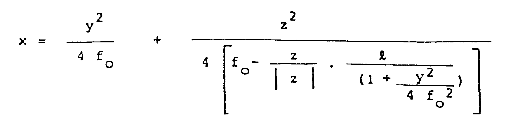
- X = demi-longueur du filament
- f = distance du centre du filament à l'origine des coordonnées
- Ox étant l'axe du réflecteur et le plan xOy étant un plan sensiblement horizontal, c'est-à-dire horizontal pour un réflecteur dont l'axe serait horizontal.
- X = half length of the filament
- f = distance from the center of the filament at the origin of the coordinates
- Ox being the axis of the reflector and the plane xOy being a substantially horizontal plane, that is to say horizontal for a reflector whose axis would be horizontal.
Une telle surface a déjà été définie dans le FR-A-2 536 502 et FR-A-2 536 503, auxquels on se reportera pour de plus amples détails.Such a surface has already been defined in FR-A-2 536 502 and FR-A-2 536 503, to which reference will be made for further details.
De préférence, lorsqu'une telle surface est utilisée, la distance séparant, en direction radiale, la surface du réflecteur de la surface définie par l'équation n'excède pas 0,15 mm.Preferably, when such a surface is used, the distance separating, in the radial direction, the surface of the reflector from the surface defined by the equation does not exceed 0.15 mm.
De préférence également, l'écart normal séparant, dans le plan vertical passant par l'origine des coordonnées, la trace de la surface du réflecteur de la parabole des moindres carrés correspondante n'excède pas 0,3 mm (la notion de "parabole des moindres carrés" est explicitée dans les deux documents précités).Preferably also, the normal difference separating, in the vertical plane passing through the origin of the coordinates, the trace of the surface of the reflector of the corresponding least-square parabola does not exceed 0.3 mm (the concept of "parabola least squares "is explained in the two aforementioned documents).
De préférence également, la distance de la surface émissive à l'axe n'excède 25 % du diamètre du filament, dans un sens ou dans l'autre.Also preferably, the distance from the emissive surface to the axis does not exceed 25% of the diameter of the filament, in one direction or the other.
De préférence également, le centrage axial du filament par rapport au point de coordonnées (f 0 o, o) est réalisé avec une tolérance de 10 % de la longueur du filament, dans un sens ou dans l'autre.Preferably also, the axial centering of the filament relative to the point of coordinates (f 0 o, o) is carried out with a tolerance of 10% of the length of the filament, in one direction or the other.
Les figures 4 à 11 et la figure 12 montrent l'éclairement procuré par les régions 12 à 16 et 11, respectivement, du réflecteur nu ainsi défini, avec un axe Ox horizontal.Figures 4 to 11 and Figure 12 show the illumination provided by
Les régions 12' à 19' produisent un éclairement symétrique par rapport à la verticale vv' des éclairements produits par les régions 12 à 19, respectivement.The
Sur ces figures, la courbe la plus extérieure correspond à un éclairement de 100 candelas, la courbe suivante à un éclairement de 1000 candelas et les autres courbes à des éclairements croissants de 2000, 4000, .... candelas.In these figures, the outermost curve corresponds to an illumination of 100 candelas, the next curve to an illumination of 1000 candelas and the other curves to increasing illuminations of 2000, 4000, .... candelas.
L'emploi du réflecteur ainsi défini seul n'est pas suffisant (contrairement au cas des deux documents précités) pour obtenir la coupure souhaitée.The use of the reflector thus defined alone is not sufficient (unlike the case of the two above-mentioned documents) to obtain the desired cut.
C'est pourquoi, au lieu de conserver un axe de réflecteur Ox horizontal (comme c'était le cas dans les deux documents précités), on incline l'ensemble filament-réflecteur vers le bas et vers la droite en direction du point de concentration maximal tel que défini par la norme SAE J 579 c, comme indiqué plus haut.This is why, instead of keeping a horizontal Ox reflector axis (as was the case in the two above-mentioned documents), the filament-reflector assembly is tilted down and to the right towards the concentration point. maximum as defined by standard SAE J 579 c, as indicated above.
Il est alors nécessaire de ramener les images produites par les régions latérales du réflecteur (régions 16 à 19 et 16' à 19') au niveau des deux demi-plans de la coupure, par des moyens correcteurs appropriés.It is then necessary to bring the images produced by the lateral regions of the reflector (
Dans un premier mode de réalisation, ces moyens correcteurs sont constitués de prismes formés sur les régions homologues 30b et 30c de la glace de fermeture (figure 3), qui sont pourvues de prismes de 1 à 3°. La région centrale 30a de la glace de fermeture peut être striée de manière classique, pour obtenir le confort et l'élargissement souhaités pour le faisceau lumineux.In a first embodiment, these correcting means consist of prisms formed on the
Dans un second mode de réalisation, illustré figures13 à 15, la surface 10a du réflecteur est prolongée par deux surfaces latérales 10b et 10c de même équation, mais légèrement décaléesangulairement (comme on peut le voir figure 15), d'un angle également de l'ordre de 1 à 3°.In a second embodiment, illustrated in FIGS. 13 to 15, the
En d'autres termes, on modifie le réflecteur du mode de réalisation précédent (figure 2) en conservant la même équation de surface, à ceci près que l'on bascule très légèrement vers le haut la partie comprenant les régions 16 à 19 d'une part, et celle comprenant les régions 16' à 19' d'autre part. Dans ce mode de réalisation, les régions 30b et 30c de la glace de fermeture peuvent être dépourvues de prismes, ou seulement très faiblement prismées, ce qui permet de supprimer les facteurs d'éblouissement dus à la multiplicité des dépouilles horizontales résultant de la présence des prismes dans le cas précédent.In other words, the reflector of the preceding embodiment is modified (FIG. 2) while retaining the same surface equation, except that the part comprising the
Dans l'un ou l'autre mode de réalisation, le projecteur selon l'invention est capable de recueillir un flux lumineux bien supérieur à celui donné par un paraboloide d'un projecteur à filament axial de conception classique, projecteur dont la focale peut difficilement être réduite à des valeurs inférieures à 29 mm.In either embodiment, the projector according to the invention is capable of collecting a luminous flux much higher than that given by a paraboloid of an axial filament projector of conventional design, projector whose focal length can hardly be reduced to values less than 29 mm.
Au contraire, pour le projecteur de l'invention, il est possible d'utiliser une focale de base f0 faible, par exemple de 22,5 mm, ce qui permet de réaliser par exemple un projecteur de forme générale rectangulaire, symétrique, de 70 mm de hauteur et de 150 mm de largeur.On the contrary, for the headlight of the invention, it is possible to use a low base focal length f 0 , for example of 22.5 mm, which makes it possible for example to produce a headlight of generally rectangular, symmetrical shape, of 70 mm high and 150 mm wide.
Le gain en flux est alors de près de 30 % par rapport auxprojecteurs classiques, dont la focale la plus courante est de 31,75 mm et la hauteur toujours limitée à des valeurs minimales de l'ordre de 100 mm.The gain in flow is then close to 30% compared to conventional projectors, the most common focal length of which is 31.75 mm and the height always limited to minimum values of the order of 100 mm.
Claims (11)
caractérisé :
characterized:

Applications Claiming Priority (2)
| Application Number | Priority Date | Filing Date | Title |
|---|---|---|---|
| FR8508655A FR2583139B1 (en) | 1985-06-07 | 1985-06-07 | CROSSING PROJECTOR FOR MOTOR VEHICLE |
| FR8508655 | 1985-06-07 |
Publications (2)
| Publication Number | Publication Date |
|---|---|
| EP0208574A1 true EP0208574A1 (en) | 1987-01-14 |
| EP0208574B1 EP0208574B1 (en) | 1989-08-02 |
Family
ID=9320001
Family Applications (1)
| Application Number | Title | Priority Date | Filing Date |
|---|---|---|---|
| EP86401216A Expired EP0208574B1 (en) | 1985-06-07 | 1986-06-05 | Dipped headlamp for a motor vehicle |
Country Status (8)
| Country | Link |
|---|---|
| US (1) | US4797797A (en) |
| EP (1) | EP0208574B1 (en) |
| JP (1) | JPS61285601A (en) |
| AU (1) | AU579015B2 (en) |
| BR (1) | BR8602630A (en) |
| CA (1) | CA1278784C (en) |
| DE (1) | DE3664807D1 (en) |
| FR (1) | FR2583139B1 (en) |
Cited By (1)
| Publication number | Priority date | Publication date | Assignee | Title |
|---|---|---|---|---|
| EP0439406A1 (en) * | 1990-01-26 | 1991-07-31 | Valeo Vision | Headlight with improved light source |
Families Citing this family (9)
| Publication number | Priority date | Publication date | Assignee | Title |
|---|---|---|---|---|
| JP2622564B2 (en) * | 1986-12-30 | 1997-06-18 | ヴァレオ ヴイジョン | Automotive headlamp with deformed bottom that emits a beam defined by a cut-off |
| FR2609146B1 (en) * | 1986-12-30 | 1990-01-05 | Cibie Projecteurs | MOTOR VEHICLE PROJECTOR COMPRISING A MODIFIED BACKGROUND PARABOLIC REFLECTOR |
| FR2609148B1 (en) * | 1986-12-30 | 1991-07-12 | Cibie Projecteurs | MOTOR VEHICLE PROJECTOR COMPRISING A REFLEXER WITH A MODIFIED BOTTOM COMPLEX SURFACE |
| US5481443A (en) * | 1993-05-19 | 1996-01-02 | The Genlyte Group, Inc. | In-ground directional light fixture |
| FR2732747B1 (en) * | 1995-04-06 | 1997-06-20 | Valeo Vision | MOTOR VEHICLE PROJECTOR CAPABLE OF TRANSMITTING A BEAM DELIMITED BY A CUT TO TWO HALF PLANS OFFSET IN HEIGHT |
| DE19843986B4 (en) * | 1998-09-25 | 2012-02-23 | Automotive Lighting Reutlingen Gmbh | Headlights for vehicles |
| US20080186717A1 (en) * | 2007-02-01 | 2008-08-07 | Genlyte Thomas Group Llc | Compact In-Grade Luminaire |
| US7524078B1 (en) | 2008-01-18 | 2009-04-28 | Genlyte Thomas Group Llc | In-grade lighting fixture |
| US7905621B1 (en) | 2008-01-18 | 2011-03-15 | Genlyte Thomas Group, Llc | In-grade lighting fixture |
Citations (4)
| Publication number | Priority date | Publication date | Assignee | Title |
|---|---|---|---|---|
| FR2087317A5 (en) * | 1970-05-14 | 1971-12-31 | Cibie Projecteurs | |
| FR2536503A1 (en) * | 1982-11-19 | 1984-05-25 | Cibie Projecteurs | Fog-lamp for an automobile |
| GB2130704A (en) * | 1982-11-19 | 1984-06-06 | Cibie Projecteurs | Dipped headlamp for automobiles |
| US4481563A (en) * | 1982-05-10 | 1984-11-06 | Corning Glass Works | Automotive headlight having optics in the reflector |
Family Cites Families (4)
| Publication number | Priority date | Publication date | Assignee | Title |
|---|---|---|---|---|
| US1566590A (en) * | 1925-12-22 | godley | ||
| US1686543A (en) * | 1927-02-02 | 1928-10-09 | William H Wood | Vehicle headlight |
| FR2396240A1 (en) * | 1977-07-01 | 1979-01-26 | Cibie Projecteurs | LARGE OPENING CROSSING-ROAD PROJECTOR FOR MOTOR VEHICLES |
| JPS5459781U (en) * | 1977-10-04 | 1979-04-25 |
-
1985
- 1985-06-07 FR FR8508655A patent/FR2583139B1/en not_active Expired
- 1985-07-30 JP JP60166933A patent/JPS61285601A/en active Granted
-
1986
- 1986-05-28 AU AU58041/86A patent/AU579015B2/en not_active Ceased
- 1986-05-28 CA CA000510232A patent/CA1278784C/en not_active Expired - Lifetime
- 1986-06-05 BR BR8602630A patent/BR8602630A/en not_active IP Right Cessation
- 1986-06-05 EP EP86401216A patent/EP0208574B1/en not_active Expired
- 1986-06-05 DE DE8686401216T patent/DE3664807D1/en not_active Expired
-
1987
- 1987-06-25 US US07/067,432 patent/US4797797A/en not_active Expired - Lifetime
Patent Citations (4)
| Publication number | Priority date | Publication date | Assignee | Title |
|---|---|---|---|---|
| FR2087317A5 (en) * | 1970-05-14 | 1971-12-31 | Cibie Projecteurs | |
| US4481563A (en) * | 1982-05-10 | 1984-11-06 | Corning Glass Works | Automotive headlight having optics in the reflector |
| FR2536503A1 (en) * | 1982-11-19 | 1984-05-25 | Cibie Projecteurs | Fog-lamp for an automobile |
| GB2130704A (en) * | 1982-11-19 | 1984-06-06 | Cibie Projecteurs | Dipped headlamp for automobiles |
Cited By (3)
| Publication number | Priority date | Publication date | Assignee | Title |
|---|---|---|---|---|
| EP0439406A1 (en) * | 1990-01-26 | 1991-07-31 | Valeo Vision | Headlight with improved light source |
| FR2657680A1 (en) * | 1990-01-26 | 1991-08-02 | Valeo Vision | MOTOR VEHICLE PROJECTOR HAVING AN IMPROVED LUMINOUS SOURCE. |
| US5124891A (en) * | 1990-01-26 | 1992-06-23 | Valeo Vision | Motor vehicle headlight including an improved light source |
Also Published As
| Publication number | Publication date |
|---|---|
| JPS61285601A (en) | 1986-12-16 |
| FR2583139A1 (en) | 1986-12-12 |
| DE3664807D1 (en) | 1989-09-07 |
| AU5804186A (en) | 1986-12-11 |
| JPH039561B2 (en) | 1991-02-08 |
| BR8602630A (en) | 1987-02-03 |
| EP0208574B1 (en) | 1989-08-02 |
| FR2583139B1 (en) | 1989-02-03 |
| CA1278784C (en) | 1991-01-08 |
| AU579015B2 (en) | 1988-11-10 |
| US4797797A (en) | 1989-01-10 |
Similar Documents
| Publication | Publication Date | Title |
|---|---|---|
| EP0581679B1 (en) | Vehicle headlamp comprising a double filament lamp for selectively producing a fog beam and a high beam | |
| EP2871406B1 (en) | Primary optical element, lighting module and headlight for motor vehicle | |
| EP0250284B1 (en) | Dipped headlamp without a cap and having an offset concentration | |
| EP0373065B1 (en) | Motor vehicle headlight comprising a reflector with a complex surface including modified intermediary zones | |
| FR2536502A1 (en) | CROSSING PROJECTOR FOR MOTOR VEHICLE | |
| EP0208574B1 (en) | Dipped headlamp for a motor vehicle | |
| FR2536503A1 (en) | Fog-lamp for an automobile | |
| EP0684420B1 (en) | Headlamp comprising a double filament lamp for low and high beam distribution | |
| FR2609148A1 (en) | Motor vehicle lamp comprising a reflector with complex surface and modified base | |
| EP0247936B1 (en) | Dipped headlamp without a cap and having an offset concentration | |
| EP0628765B1 (en) | Vehicle headlamp with ellipsoidal type light reflector | |
| EP0256930A1 (en) | Fog lamp with transverse filament for motor vehicles | |
| EP0250313A1 (en) | Additional headlamp to a dipped headlamp for a motor vehicle | |
| EP0645578B1 (en) | Projector with smooth cover lens, particularly for vehicles, and manufacturing process for the reflector of same | |
| FR2902496A1 (en) | LIGHTING INSTALLATION FOR VEHICLE | |
| EP1944542B1 (en) | Double-function headlight for an automobile | |
| EP0258116B1 (en) | Dipped and main beam headlamp with two transverse filaments for a motor vehicle | |
| FR2760070A1 (en) | PROJECTOR COMPRISING A TWO-FILAMENT LAMP FOR GENERATING A CUT BEAM AND AN UNCUT BEAM | |
| FR2793542A1 (en) | Elliptical headlamp providing dual functions on motor vehicle, giving optimum high and low beam operation of the headlamp | |
| FR2754039A1 (en) | ELLIPTICAL GENERATOR PROJECTOR FOR A MOTOR VEHICLE HAVING AN IMPROVED CUTTING COVER, AND METHOD OF MANUFACTURING THE CACHE | |
| EP0926431A1 (en) | Motor vehicle headlamp comprising a single reflector and a displaceable light source for generating two different light beams | |
| FR2889289A1 (en) | Illumination headlamp for motor vehicle, has bifocal lens with front convex faces to admit distinct focuses placed near ellipsoidal portion focuses whose distance is less than/equal to half of transversal dimension of headlamp front opening | |
| FR2597575A1 (en) | Reflector, in particular for motor vehicle lamp | |
| FR2769687A1 (en) | LEFT AND RIGHT MOTOR VEHICLE ASSEMBLY WITH IMPROVED PHOTOMETRIC PROPERTIES | |
| FR2789476A1 (en) | ELLIPTICAL PROJECTOR FOR A MOTOR VEHICLE, LIKELY TO TRANSMIT A BEAM WITHOUT CUT |
Legal Events
| Date | Code | Title | Description |
|---|---|---|---|
| PUAI | Public reference made under article 153(3) epc to a published international application that has entered the european phase |
Free format text: ORIGINAL CODE: 0009012 |
|
| AK | Designated contracting states |
Kind code of ref document: A1 Designated state(s): DE GB IT |
|
| 17P | Request for examination filed |
Effective date: 19870302 |
|
| 17Q | First examination report despatched |
Effective date: 19880707 |
|
| GRAA | (expected) grant |
Free format text: ORIGINAL CODE: 0009210 |
|
| RAP1 | Party data changed (applicant data changed or rights of an application transferred) |
Owner name: VALEO VISION |
|
| AK | Designated contracting states |
Kind code of ref document: B1 Designated state(s): DE GB IT |
|
| GBT | Gb: translation of ep patent filed (gb section 77(6)(a)/1977) | ||
| REF | Corresponds to: |
Ref document number: 3664807 Country of ref document: DE Date of ref document: 19890907 |
|
| ITF | It: translation for a ep patent filed |
Owner name: SOCIETA' ITALIANA BREVETTI S.P.A. |
|
| PLBE | No opposition filed within time limit |
Free format text: ORIGINAL CODE: 0009261 |
|
| STAA | Information on the status of an ep patent application or granted ep patent |
Free format text: STATUS: NO OPPOSITION FILED WITHIN TIME LIMIT |
|
| 26N | No opposition filed | ||
| ITTA | It: last paid annual fee | ||
| REG | Reference to a national code |
Ref country code: GB Ref legal event code: IF02 |
|
| PGFP | Annual fee paid to national office [announced via postgrant information from national office to epo] |
Ref country code: GB Payment date: 20030529 Year of fee payment: 18 |
|
| PGFP | Annual fee paid to national office [announced via postgrant information from national office to epo] |
Ref country code: DE Payment date: 20030611 Year of fee payment: 18 |
|
| PG25 | Lapsed in a contracting state [announced via postgrant information from national office to epo] |
Ref country code: GB Free format text: LAPSE BECAUSE OF NON-PAYMENT OF DUE FEES Effective date: 20040605 |
|
| PG25 | Lapsed in a contracting state [announced via postgrant information from national office to epo] |
Ref country code: DE Free format text: LAPSE BECAUSE OF NON-PAYMENT OF DUE FEES Effective date: 20050101 |
|
| GBPC | Gb: european patent ceased through non-payment of renewal fee |
Effective date: 20040605 |
|
| PG25 | Lapsed in a contracting state [announced via postgrant information from national office to epo] |
Ref country code: IT Free format text: LAPSE BECAUSE OF NON-PAYMENT OF DUE FEES;WARNING: LAPSES OF ITALIAN PATENTS WITH EFFECTIVE DATE BEFORE 2007 MAY HAVE OCCURRED AT ANY TIME BEFORE 2007. THE CORRECT EFFECTIVE DATE MAY BE DIFFERENT FROM THE ONE RECORDED. Effective date: 20050605 |