EP0207899A2 - Plant and process for defrosting blocks of food products - Google Patents
Plant and process for defrosting blocks of food products Download PDFInfo
- Publication number
- EP0207899A2 EP0207899A2 EP86830142A EP86830142A EP0207899A2 EP 0207899 A2 EP0207899 A2 EP 0207899A2 EP 86830142 A EP86830142 A EP 86830142A EP 86830142 A EP86830142 A EP 86830142A EP 0207899 A2 EP0207899 A2 EP 0207899A2
- Authority
- EP
- European Patent Office
- Prior art keywords
- product
- flakes
- tank
- exchanger
- plant according
- Prior art date
- Legal status (The legal status is an assumption and is not a legal conclusion. Google has not performed a legal analysis and makes no representation as to the accuracy of the status listed.)
- Granted
Links
- 238000010257 thawing Methods 0.000 title claims abstract description 27
- 235000013305 food Nutrition 0.000 title claims abstract description 8
- 238000000034 method Methods 0.000 title claims description 8
- 230000003134 recirculating effect Effects 0.000 claims abstract description 7
- 239000007788 liquid Substances 0.000 claims description 8
- 239000007787 solid Substances 0.000 claims description 8
- 238000005086 pumping Methods 0.000 claims description 4
- 239000000725 suspension Substances 0.000 claims description 4
- 235000013601 eggs Nutrition 0.000 claims description 3
- 238000005406 washing Methods 0.000 claims description 2
- 239000000047 product Substances 0.000 description 36
- 238000010438 heat treatment Methods 0.000 description 9
- 239000012530 fluid Substances 0.000 description 5
- 230000015572 biosynthetic process Effects 0.000 description 3
- 238000011109 contamination Methods 0.000 description 2
- 230000002427 irreversible effect Effects 0.000 description 2
- XLYOFNOQVPJJNP-UHFFFAOYSA-N water Substances O XLYOFNOQVPJJNP-UHFFFAOYSA-N 0.000 description 2
- 238000013019 agitation Methods 0.000 description 1
- 230000004075 alteration Effects 0.000 description 1
- 239000003599 detergent Substances 0.000 description 1
- 235000013345 egg yolk Nutrition 0.000 description 1
- 210000002969 egg yolk Anatomy 0.000 description 1
- 230000008014 freezing Effects 0.000 description 1
- 238000007710 freezing Methods 0.000 description 1
- 230000005484 gravity Effects 0.000 description 1
- 239000012263 liquid product Substances 0.000 description 1
- 230000000284 resting effect Effects 0.000 description 1
- 239000000523 sample Substances 0.000 description 1
- 230000003068 static effect Effects 0.000 description 1
Images
Classifications
-
- A—HUMAN NECESSITIES
- A23—FOODS OR FOODSTUFFS; TREATMENT THEREOF, NOT COVERED BY OTHER CLASSES
- A23B—PRESERVATION OF FOODS, FOODSTUFFS OR NON-ALCOHOLIC BEVERAGES; CHEMICAL RIPENING OF FRUIT OR VEGETABLES
- A23B2/00—Preservation of foods or foodstuffs, in general
- A23B2/80—Freezing; Subsequent thawing; Cooling
- A23B2/82—Thawing subsequent to freezing
-
- A—HUMAN NECESSITIES
- A23—FOODS OR FOODSTUFFS; TREATMENT THEREOF, NOT COVERED BY OTHER CLASSES
- A23B—PRESERVATION OF FOODS, FOODSTUFFS OR NON-ALCOHOLIC BEVERAGES; CHEMICAL RIPENING OF FRUIT OR VEGETABLES
- A23B5/00—Preservation of eggs or egg products
- A23B5/04—Freezing; Subsequent thawing; Cooling
- A23B5/045—Thawing subsequent to freezing
-
- A—HUMAN NECESSITIES
- A23—FOODS OR FOODSTUFFS; TREATMENT THEREOF, NOT COVERED BY OTHER CLASSES
- A23G—COCOA; COCOA PRODUCTS, e.g. CHOCOLATE; SUBSTITUTES FOR COCOA OR COCOA PRODUCTS; CONFECTIONERY; CHEWING GUM; ICE-CREAM; PREPARATION THEREOF
- A23G9/00—Frozen sweets, e.g. ice confectionery, ice-cream; Mixtures therefor
- A23G9/04—Production of frozen sweets, e.g. ice-cream
- A23G9/045—Production of frozen sweets, e.g. ice-cream of slush-ice, e.g. semi-frozen beverage
Definitions
- the present invention relates to a plant for defrosting blocks of food products, particularly deep-frozen eggs, of the type including a flaking roller and means for thawing the flakes, as well as to a process carried out by this plant.
- Deep-frozen blocks of food products must be defrosted in short times so as to avoid alteration of the products and render the process economically advantageous.
- Defrosting at ambient temperatures or in heated chambers has the disadvantages of considerably long operating times, the possibility of contamination due to the manual handling, and of regulation by operators.
- defrosting systems which use thawing grids and heatedArchimedean screws.
- Such systems have sizeable hot surfaces with which the deep-frozen product is in contact. This essentially static contact may cause irreversible changes when the product has a high protein content, for example as in egg yolks. These changes may, moreover, cause clogging of the thawing grids or of the heated screws.
- Another defrosting method is that which uses rollers having blades for flaking the deep-frozen products.
- the flakes are subsequently thawed in systems similar to the thawing grids and hence with the same problems.
- the storage of the product because of the presence of unthawed flakes, may result in large solid masses collecting in the tank, with considerable problems as regards the pumping of the product for use.
- the object of the present invention is to provide a highly automated plant for defrosting blocks of food products which does not have these disadvantages and which at the same time is cheap to make.
- a further object of the present invention is to provide a process for defrosting blocks of food products which, as well as not having the aforesaid problems, is quick and safe from the point of view of lack of changes in the defrosted product.
- the means for thawing the flakes include a tank for collecting the flakes, a heat exchanger, and means for transferring the flakes and the thawed product to the heat exchanger and for recirculating them to the collecting tanks so as to achieve rapid thawing of the product with a uniform temperature in the liquid mass slightly above freezing.
- the thawing of the product occurs at temperatures such as not to cause irreversible changes in the product itself in that the high coefficient of heat exchange achieved in the heat exchanger allows the use of heating fluids at lower temperatures than in known heating systems with hot walls. Furthermore, the high turbulence achieved in the heat exchanger enables any localised temperature increases in the product to be avoided, ensuring that the heat exchanged substantially balances the latent heat of thawing of the treated product.
- the collecting tank has agitators and is provided at its upper end with a sprinkler-diffuser through which the product is recirculated.
- the exchanger is of the concentric-tube type and includes a series of mesh filter elements within the tube in which the product flows.
- This device has the advantage that the flakes are partly broken up, even though solid, by the mesh filter elements under the pressure exerted by the pump means.
- the breaking of the flakes considerably reduces their thermal capacity and thus also reduces the time and degree of recirculation necessary to achieve complete thawing of the product.
- the defrosting process is characterised in that the thawing of the flakes is achieved by the pumping of the flakes and the thawed product from the collecting tank to a heat exchanger, the recirculation of the product from the exchanger to the tank until the product has thawed to the desired extent, and the removal of the product itself.
- the tipper-elevator 18 has a loading plane 20 articulated at 22 to the elevator 18 and provided with idle wheels 24 resting on suitable guides of the elevator 18.
- the elevator 18 has cam surfaces 26 close to the inclined plane 20 and in correspondence with the guides.
- the flaking roller 10 is located above a closed tank 28 having an inclined bottom 30 and an upper wall 32.
- a motor 34 is fixed to the outside of the wall 32 and, during operation of the plant, drives a bladed agitator 36 through a vertical shaft 38.
- the wall 32 has an aperture 40 in correspondence with a duct 42 enclosing the flaking roller 10.
- the tank 28 has a sprinkler-diffuser 44 supported by the wall 32.
- the tank 28 also has a level sensor 46 located on a side wall at a height slightly above the agitator 36.
- the tank 28 has a discharge pipe 48 which connects the tank itself to a hollow-bodied volumetric pump 50.
- the delivery of the pump 50 is connected to a concentric-tube heat exchanger 52 supported by a structure 54.
- the exchanger 52 includes a thermostatically-controlled vessel 54 for the heating fluid, normally water, heated by an electrical resistance 56.
- the heating fluid is circulated in jackets 62 surrounding the central tube 64 by means of a recirculating pump 58 and tubing 60.
- the central tube 64 of the exchanger 52 has larger-diameter portions 64a around which there is no heating jacket 62.
- the portions 64a are connected to the preceding tube 64 (in the direction of flow of the product) by frusto-conical connectors 64b and house tubular mesh filter elements 66 of the same diameter as the internal tube 64 of the exchanger 52.
- the portions 64a At their ends opposite the frusto-conical connectors 64b, the portions 64a have blind closure flanges 68 and connectors 70 perpendicular to the side walls of the portions 64a.
- Each filter element 66 is in contact at one end with the tube 64 of the exchanger and at its other end with the blind flange 68.
- the plant illustrated in the drawing has three identical portions 64a, the only difference relating to the tubular filter elements 66 which have mesh sizes that decrease from the first to the third element.
- a recirculating tube 72 which connects the exchanger itself to the diffuser 44 of the collecting tank 28.
- the tube 72 includes an on-off valve 74 and a valve 76 for delivery of the product into a storage tank 78 for the thawed product.
- the deep-frozen blocks 14 are advanced stepwise on the conveyor belt 16 and are loaded onto the plane 20 of the elevator 18 which raises the blocks themselves to the level of the flaking roller 10.
- the wheels 24 of the plane 20 engage the cams so as to rotate the plane 20 about the articulation axis 22 whereby the blocks 14 slide by gravity onto the inclined plane 20 and bear against the roller 10 driven by a motor (not illustrated).
- the roller 10 reduces the blocks 14 to flakes 14a by means of the blades 12 and the flakes fall onto the inclined bottom of the tank 28.
- a sufficient head of liquid (water or thawed product) will be provided in the tank 28 to enable the volumetric pump 50 to be started.
- the agitator 36 maintains a uniform suspension of flakes in the liquid without danger of the formation of solid masses because of the low temperature of the flakes. Indeed, the temperature of the blocks 14 and hence of the flakes 14a is of the order of -20°C, whereby, in the absence of agitation, the flakes could cause part of the liquid in contact with them in the tank 28 to freeze and render the operation of the plant problematical.
- the suspension of solid flakes and liquid product is pumped to the exchanger 52 in which the heating fluid is kept at a temperature of between 20 and 40°C.
- the pumped product is filtered through the first tubular mesh filter element 66 in which the flakes of product undergo a first crushing, being forced through the filter mesh by the pressure exerted by the pump 50.
- the filter portion 64a On leaving the filter portion 64a through the connector 70, the product undergoes further heating as it passes through a second section of the exchanger 52 and reaches the second portion 64a in which the product is filtered through a finer-mesh element 66.
- the suspension On leaving the exchanger 52, the suspension will thus contain a smaller percentage of solids due to thawing as a result of the heat exchange and smaller flakes due both to the thawing and particularly to the crushing as a result of the forcing through the filter element 66 by the pressure of the pump 50.
- the product thus transformed is recirculated to the tank 28 through the sprinkler-diffuser 44 which, together with the agitator 36, avoids the formation of solid masses.
- valve 74 When the product has thawed to the desired extent, the valve 74 is closed and the valve 76 is opened to transfer the product to the storage tank 78.
- the transfer will be effected as long as the level control 46 does not indicate a minimum level within the tank 28 to enable the starting of the defrosting of a further batch of blocks 14.
- the probe 46 may intervene automatically to stop the operation of the pump 50.
- the plant is suitable for continuous operation subject to accurate regulation and control of all the variables in play. Equally, the product delivered may be sent directly for use instead of to the storage tank.
- the product leaving the plant has a temperature of about 1 to 2°C, thus ensuring the absence of any thermal changes in the product. Moreover, the automatic operation of the plant minimises the possibility of accidental contamination of the product.
- the plant also has an automatic washing unit (not illustrated) which automatically directs a liquid containing detergent into the tank 28 and along all the tubes of the plant when the plant itself has finished operating.
- an automatic washing unit (not illustrated) which automatically directs a liquid containing detergent into the tank 28 and along all the tubes of the plant when the plant itself has finished operating.
Landscapes
- Life Sciences & Earth Sciences (AREA)
- Engineering & Computer Science (AREA)
- Chemical & Material Sciences (AREA)
- Food Science & Technology (AREA)
- Polymers & Plastics (AREA)
- Wood Science & Technology (AREA)
- Zoology (AREA)
- Defrosting Systems (AREA)
- Freezing, Cooling And Drying Of Foods (AREA)
- General Preparation And Processing Of Foods (AREA)
- Bakery Products And Manufacturing Methods Therefor (AREA)
- Agricultural Chemicals And Associated Chemicals (AREA)
Abstract
Description
- The present invention relates to a plant for defrosting blocks of food products, particularly deep-frozen eggs, of the type including a flaking roller and means for thawing the flakes, as well as to a process carried out by this plant.
- Deep-frozen blocks of food products must be defrosted in short times so as to avoid alteration of the products and render the process economically advantageous. Defrosting at ambient temperatures or in heated chambers has the disadvantages of considerably long operating times, the possibility of contamination due to the manual handling, and of regulation by operators.
- In order to shorten the operating times, defrosting systems have been adopted which use thawing grids and heatedArchimedean screws. Such systems have sizeable hot surfaces with which the deep-frozen product is in contact. This essentially static contact may cause irreversible changes when the product has a high protein content, for example as in egg yolks. These changes may, moreover, cause clogging of the thawing grids or of the heated screws.
- Another defrosting method is that which uses rollers having blades for flaking the deep-frozen products. The flakes are subsequently thawed in systems similar to the thawing grids and hence with the same problems. Moreover, the storage of the product, because of the presence of unthawed flakes, may result in large solid masses collecting in the tank, with considerable problems as regards the pumping of the product for use.
- The object of the present invention is to provide a highly automated plant for defrosting blocks of food products which does not have these disadvantages and which at the same time is cheap to make.
- A further object of the present invention is to provide a process for defrosting blocks of food products which, as well as not having the aforesaid problems, is quick and safe from the point of view of lack of changes in the defrosted product.
- According to the invention this is achieved by virtue of the fact that the means for thawing the flakes include a tank for collecting the flakes, a heat exchanger, and means for transferring the flakes and the thawed product to the heat exchanger and for recirculating them to the collecting tanks so as to achieve rapid thawing of the product with a uniform temperature in the liquid mass slightly above freezing.
- By virtue of these characteristics, the thawing of the product occurs at temperatures such as not to cause irreversible changes in the product itself in that the high coefficient of heat exchange achieved in the heat exchanger allows the use of heating fluids at lower temperatures than in known heating systems with hot walls. Furthermore, the high turbulence achieved in the heat exchanger enables any localised temperature increases in the product to be avoided, ensuring that the heat exchanged substantially balances the latent heat of thawing of the treated product.
- According to the invention, the collecting tank has agitators and is provided at its upper end with a sprinkler-diffuser through which the product is recirculated.
- This avoids the possible formation of solid masses within the tank and ensures that there is a sufficient head of liquid in the bottom of the tank itself for the pump means to recirculate the product.
- According to a further characteristic, the exchanger is of the concentric-tube type and includes a series of mesh filter elements within the tube in which the product flows.
- This device has the advantage that the flakes are partly broken up, even though solid, by the mesh filter elements under the pressure exerted by the pump means. The breaking of the flakes considerably reduces their thermal capacity and thus also reduces the time and degree of recirculation necessary to achieve complete thawing of the product.
- According to the invention, the defrosting process is characterised in that the thawing of the flakes is achieved by the pumping of the flakes and the thawed product from the collecting tank to a heat exchanger, the recirculation of the product from the exchanger to the tank until the product has thawed to the desired extent, and the removal of the product itself.
- Further advantages and characteristics of the plant and the process according to the present invention will become clear from the detailed description which follows, purely by way of non-limiting example, with reference to the appended drawings, in which:
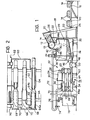
- Figure 1 is a schematic partially-sectioned side view of the plant, and
- Figure 2 is an enlarged detail of Figure 1.
- With reference to the drawings, there is shown a
flaking roller 10 withcircumferential blades 12. Deep-frozenblocks 14 are fed automatically to theroller 10 by means of aconveyor belt 16, a tipper-elevator 18, and aninclined plane 20. The tipper-elevator 18 has aloading plane 20 articulated at 22 to theelevator 18 and provided withidle wheels 24 resting on suitable guides of theelevator 18. - The
elevator 18 hascam surfaces 26 close to theinclined plane 20 and in correspondence with the guides. - The
flaking roller 10 is located above a closedtank 28 having aninclined bottom 30 and anupper wall 32. Amotor 34 is fixed to the outside of thewall 32 and, during operation of the plant, drives abladed agitator 36 through avertical shaft 38. - The
wall 32 has anaperture 40 in correspondence with aduct 42 enclosing theflaking roller 10. In its upper part, thetank 28 has a sprinkler-diffuser 44 supported by thewall 32. Thetank 28 also has alevel sensor 46 located on a side wall at a height slightly above theagitator 36. - In the lowest part of the
inclined bottom 30, thetank 28 has adischarge pipe 48 which connects the tank itself to a hollow-bodiedvolumetric pump 50. The delivery of thepump 50 is connected to a concentric-tube heat exchanger 52 supported by astructure 54. Theexchanger 52 includes a thermostatically-controlledvessel 54 for the heating fluid, normally water, heated by anelectrical resistance 56. The heating fluid is circulated injackets 62 surrounding thecentral tube 64 by means of a recirculatingpump 58 andtubing 60. Thecentral tube 64 of theexchanger 52 has larger-diameter portions 64a around which there is noheating jacket 62. The portions 64a are connected to the preceding tube 64 (in the direction of flow of the product) by frusto-conical connectors 64b and house tubularmesh filter elements 66 of the same diameter as theinternal tube 64 of theexchanger 52. - At their ends opposite the frusto-
conical connectors 64b, the portions 64a haveblind closure flanges 68 andconnectors 70 perpendicular to the side walls of the portions 64a. Eachfilter element 66 is in contact at one end with thetube 64 of the exchanger and at its other end with theblind flange 68. - The plant illustrated in the drawing has three identical portions 64a, the only difference relating to the
tubular filter elements 66 which have mesh sizes that decrease from the first to the third element. - At the outlet of the last portion 64a of the
heat exchanger 52 there is arecirculating tube 72 which connects the exchanger itself to thediffuser 44 of thecollecting tank 28. Thetube 72 includes an on-offvalve 74 and avalve 76 for delivery of the product into astorage tank 78 for the thawed product. - During operation of the plant, the deep-frozen
blocks 14 are advanced stepwise on theconveyor belt 16 and are loaded onto theplane 20 of theelevator 18 which raises the blocks themselves to the level of theflaking roller 10. Close to thecam surfaces 26, thewheels 24 of theplane 20 engage the cams so as to rotate theplane 20 about thearticulation axis 22 whereby theblocks 14 slide by gravity onto theinclined plane 20 and bear against theroller 10 driven by a motor (not illustrated). Theroller 10 reduces theblocks 14 to flakes 14a by means of theblades 12 and the flakes fall onto the inclined bottom of thetank 28. - During the starting phase of the plant, a sufficient head of liquid (water or thawed product) will be provided in the
tank 28 to enable thevolumetric pump 50 to be started. - The
agitator 36 maintains a uniform suspension of flakes in the liquid without danger of the formation of solid masses because of the low temperature of the flakes. Indeed, the temperature of theblocks 14 and hence of the flakes 14a is of the order of -20°C, whereby, in the absence of agitation, the flakes could cause part of the liquid in contact with them in thetank 28 to freeze and render the operation of the plant problematical. - The suspension of solid flakes and liquid product is pumped to the
exchanger 52 in which the heating fluid is kept at a temperature of between 20 and 40°C. The pumped product is filtered through the first tubularmesh filter element 66 in which the flakes of product undergo a first crushing, being forced through the filter mesh by the pressure exerted by thepump 50. On leaving the filter portion 64a through theconnector 70, the product undergoes further heating as it passes through a second section of theexchanger 52 and reaches the second portion 64a in which the product is filtered through a finer-mesh element 66. The same applies to the third heating section and the third filter portion. - On leaving the
exchanger 52, the suspension will thus contain a smaller percentage of solids due to thawing as a result of the heat exchange and smaller flakes due both to the thawing and particularly to the crushing as a result of the forcing through thefilter element 66 by the pressure of thepump 50. The product thus transformed is recirculated to thetank 28 through the sprinkler-diffuser 44 which, together with theagitator 36, avoids the formation of solid masses. - When the product has thawed to the desired extent, the
valve 74 is closed and thevalve 76 is opened to transfer the product to thestorage tank 78. The transfer will be effected as long as thelevel control 46 does not indicate a minimum level within thetank 28 to enable the starting of the defrosting of a further batch ofblocks 14. Theprobe 46 may intervene automatically to stop the operation of thepump 50. - In addition to the semi-continuous operation just described, the plant is suitable for continuous operation subject to accurate regulation and control of all the variables in play. Equally, the product delivered may be sent directly for use instead of to the storage tank.
- With the heating fluid at a temperature of the order of 30°, the product leaving the plant has a temperature of about 1 to 2°C, thus ensuring the absence of any thermal changes in the product. Moreover, the automatic operation of the plant minimises the possibility of accidental contamination of the product.
- The plant also has an automatic washing unit (not illustrated) which automatically directs a liquid containing detergent into the
tank 28 and along all the tubes of the plant when the plant itself has finished operating. - It is understood that, the principle of the invention remaining the same, the constructional details and forms of embodiment may be varied widely with respect to that described and illustrated purely by way of non-limiting example, without thereby departing from the scope of the present invention.
Claims (9)
Priority Applications (1)
| Application Number | Priority Date | Filing Date | Title |
|---|---|---|---|
| AT86830142T ATE80009T1 (en) | 1985-05-28 | 1986-05-27 | DEVICE AND METHOD FOR THAWING BLOCKS OF FOOD. |
Applications Claiming Priority (2)
| Application Number | Priority Date | Filing Date | Title |
|---|---|---|---|
| IT67488/85A IT1183857B (en) | 1985-05-28 | 1985-05-28 | PLANT AND PROCESS FOR THE DEFROSTING OF BREADS OF FOOD PRODUCTS |
| IT6748885 | 1985-05-28 |
Publications (3)
| Publication Number | Publication Date |
|---|---|
| EP0207899A2 true EP0207899A2 (en) | 1987-01-07 |
| EP0207899A3 EP0207899A3 (en) | 1989-11-29 |
| EP0207899B1 EP0207899B1 (en) | 1992-09-02 |
Family
ID=11302834
Family Applications (1)
| Application Number | Title | Priority Date | Filing Date |
|---|---|---|---|
| EP86830142A Expired EP0207899B1 (en) | 1985-05-28 | 1986-05-27 | Plant and process for defrosting blocks of food products |
Country Status (4)
| Country | Link |
|---|---|
| EP (1) | EP0207899B1 (en) |
| AT (1) | ATE80009T1 (en) |
| DE (2) | DE3686608T2 (en) |
| IT (1) | IT1183857B (en) |
Cited By (4)
| Publication number | Priority date | Publication date | Assignee | Title |
|---|---|---|---|---|
| JPS6455167A (en) * | 1987-08-26 | 1989-03-02 | Nankai Kako Kk | Thawing tank apparatus for frozen particle |
| US5086086A (en) * | 1987-08-28 | 1992-02-04 | Minnesota Mining And Manufacturing Company | Energy-induced curable compositions |
| WO1993009684A1 (en) * | 1991-11-13 | 1993-05-27 | Typhoon-Martens B.V. | Method and apparatus for making a frozen mass of drinkable product ready for treatment |
| US8075175B2 (en) * | 2003-11-19 | 2011-12-13 | Grifols Therapeutics Inc. | Method for melting frozen, water-containing products in a mixer |
Family Cites Families (8)
| Publication number | Priority date | Publication date | Assignee | Title |
|---|---|---|---|---|
| US1940353A (en) * | 1929-09-10 | 1933-12-19 | Joe C Jenkins | Method of reducing frozen liquid |
| US2429909A (en) * | 1942-11-25 | 1947-10-28 | Us Cold Storage Corp | Defrosting method |
| US2373682A (en) * | 1943-02-04 | 1945-04-17 | Wilson & Company Inc | Egg thawing |
| US2478893A (en) * | 1945-11-26 | 1949-08-16 | David O Brant | Apparatus for liquefying frozen food products |
| US3182699A (en) * | 1962-07-31 | 1965-05-11 | Georges M Binon | Frozen food shaving and thawing machine |
| FR1527724A (en) * | 1966-07-20 | 1968-06-07 | Machine for defrosting or reheating grain products such as butter and the like | |
| FR1537809A (en) * | 1967-07-13 | 1968-08-30 | Process and device for the manufacture of food products based on frozen raw materials, as well as products conforming to those obtained | |
| US3636308A (en) * | 1970-04-09 | 1972-01-18 | Hatco Corp | Apparatus for reconstituting frozen food |
-
1985
- 1985-05-28 IT IT67488/85A patent/IT1183857B/en active
-
1986
- 1986-05-27 AT AT86830142T patent/ATE80009T1/en not_active IP Right Cessation
- 1986-05-27 DE DE8686830142T patent/DE3686608T2/en not_active Expired - Fee Related
- 1986-05-27 DE DE198686830142T patent/DE207899T1/en active Pending
- 1986-05-27 EP EP86830142A patent/EP0207899B1/en not_active Expired
Cited By (5)
| Publication number | Priority date | Publication date | Assignee | Title |
|---|---|---|---|---|
| JPS6455167A (en) * | 1987-08-26 | 1989-03-02 | Nankai Kako Kk | Thawing tank apparatus for frozen particle |
| US5086086A (en) * | 1987-08-28 | 1992-02-04 | Minnesota Mining And Manufacturing Company | Energy-induced curable compositions |
| WO1993009684A1 (en) * | 1991-11-13 | 1993-05-27 | Typhoon-Martens B.V. | Method and apparatus for making a frozen mass of drinkable product ready for treatment |
| US5362509A (en) * | 1991-11-13 | 1994-11-08 | Typhoon-Martens B.V. | Method and apparatus for making a frozen mass of drinkable product ready for treatment |
| US8075175B2 (en) * | 2003-11-19 | 2011-12-13 | Grifols Therapeutics Inc. | Method for melting frozen, water-containing products in a mixer |
Also Published As
| Publication number | Publication date |
|---|---|
| DE207899T1 (en) | 1987-07-02 |
| DE3686608T2 (en) | 1993-03-25 |
| EP0207899A3 (en) | 1989-11-29 |
| IT8567488A1 (en) | 1986-11-28 |
| IT8567488A0 (en) | 1985-05-28 |
| DE3686608D1 (en) | 1992-10-08 |
| IT1183857B (en) | 1987-10-22 |
| EP0207899B1 (en) | 1992-09-02 |
| ATE80009T1 (en) | 1992-09-15 |
Similar Documents
| Publication | Publication Date | Title |
|---|---|---|
| US5086693A (en) | Apparatus for heating and cooling food articles | |
| US6455085B1 (en) | Method of controlling the operation of cooking apparatus | |
| EP0568679B1 (en) | Method and apparatus for making a frozen mass of drinkable product ready for treatment | |
| AU592054B2 (en) | Food processing method and apparatus | |
| EP0207899B1 (en) | Plant and process for defrosting blocks of food products | |
| US20090123965A1 (en) | Hydrolysis Process For Raw Materials From The Fishing And Slaughterhouse Industries And Tanks For Use Therein | |
| US4189504A (en) | Method of cooking foods | |
| CN102742867B (en) | Salted egg yolk continuous baking production line | |
| US3437488A (en) | Method of and apparatus for the manufacture of fish bait | |
| JP2733377B2 (en) | Equipment for heating and cooling food | |
| EP0545578A2 (en) | Apparatus for effecting heat exchange between a liquid and a particulate material | |
| JP2007533948A (en) | Method, apparatus, system, and heat exchanger for increasing the temperature of a material that is initially at least partially solidified in a container | |
| US3516398A (en) | Apparatus for melting a frozen food product | |
| US1325094A (en) | Process for treating fruit-juices | |
| US7475629B2 (en) | Apparatus for cooking foods | |
| CN111296719A (en) | Continuous marinating device | |
| CN214842040U (en) | Vacuum drier is used in cream production | |
| GB1564743A (en) | Dehydrators | |
| JP2026501269A (en) | Material Cooling/Freezing Systems | |
| US20070082097A1 (en) | Method and apparatus for cooking particulate food material | |
| SU1111721A1 (en) | Installation for making mince meat from frozen units | |
| CA1123257A (en) | Water immersion defrosting unit | |
| AU760057B2 (en) | A method of controlling the operation of cooking apparatus | |
| AU729809B3 (en) | A method of controlling the operation of cooking apparatus | |
| CN119038050A (en) | Conveying device and conveying method for crushed frozen chicken livers |
Legal Events
| Date | Code | Title | Description |
|---|---|---|---|
| PUAI | Public reference made under article 153(3) epc to a published international application that has entered the european phase |
Free format text: ORIGINAL CODE: 0009012 |
|
| AK | Designated contracting states |
Kind code of ref document: A2 Designated state(s): AT BE CH DE FR GB IT LI LU NL SE |
|
| EL | Fr: translation of claims filed | ||
| TCAT | At: translation of patent claims filed | ||
| TCNL | Nl: translation of patent claims filed | ||
| DET | De: translation of patent claims | ||
| PUAL | Search report despatched |
Free format text: ORIGINAL CODE: 0009013 |
|
| AK | Designated contracting states |
Kind code of ref document: A3 Designated state(s): AT BE CH DE FR GB IT LI LU NL SE |
|
| 17P | Request for examination filed |
Effective date: 19900511 |
|
| 17Q | First examination report despatched |
Effective date: 19910412 |
|
| GRAA | (expected) grant |
Free format text: ORIGINAL CODE: 0009210 |
|
| AK | Designated contracting states |
Kind code of ref document: B1 Designated state(s): AT BE CH DE FR GB IT LI LU NL SE |
|
| PG25 | Lapsed in a contracting state [announced via postgrant information from national office to epo] |
Ref country code: IT Free format text: LAPSE BECAUSE OF FAILURE TO SUBMIT A TRANSLATION OF THE DESCRIPTION OR TO PAY THE FEE WITHIN THE PRE;WARNING: LAPSES OF ITALIAN PATENTS WITH EFFECTIVE DATE BEFORE 2007 MAY HAVE OCCURRED AT ANY TIME BEFORE 2007. THE CORRECT EFFECTIVE DATE MAY BE DIFFERENT FROM THE ONE RECORDED.SCRIBED TIME-LIMIT Effective date: 19920902 Ref country code: SE Effective date: 19920902 Ref country code: NL Effective date: 19920902 |
|
| REF | Corresponds to: |
Ref document number: 80009 Country of ref document: AT Date of ref document: 19920915 Kind code of ref document: T |
|
| REF | Corresponds to: |
Ref document number: 3686608 Country of ref document: DE Date of ref document: 19921008 |
|
| ET | Fr: translation filed | ||
| NLV1 | Nl: lapsed or annulled due to failure to fulfill the requirements of art. 29p and 29m of the patents act | ||
| PG25 | Lapsed in a contracting state [announced via postgrant information from national office to epo] |
Ref country code: GB Effective date: 19930527 |
|
| PLBE | No opposition filed within time limit |
Free format text: ORIGINAL CODE: 0009261 |
|
| STAA | Information on the status of an ep patent application or granted ep patent |
Free format text: STATUS: NO OPPOSITION FILED WITHIN TIME LIMIT |
|
| 26N | No opposition filed | ||
| GBPC | Gb: european patent ceased through non-payment of renewal fee |
Effective date: 19930527 |
|
| EPTA | Lu: last paid annual fee | ||
| PGFP | Annual fee paid to national office [announced via postgrant information from national office to epo] |
Ref country code: AT Payment date: 19960416 Year of fee payment: 11 |
|
| PGFP | Annual fee paid to national office [announced via postgrant information from national office to epo] |
Ref country code: DE Payment date: 19960424 Year of fee payment: 11 |
|
| PGFP | Annual fee paid to national office [announced via postgrant information from national office to epo] |
Ref country code: BE Payment date: 19960425 Year of fee payment: 11 |
|
| PGFP | Annual fee paid to national office [announced via postgrant information from national office to epo] |
Ref country code: LU Payment date: 19960501 Year of fee payment: 11 |
|
| PGFP | Annual fee paid to national office [announced via postgrant information from national office to epo] |
Ref country code: CH Payment date: 19960502 Year of fee payment: 11 |
|
| PGFP | Annual fee paid to national office [announced via postgrant information from national office to epo] |
Ref country code: FR Payment date: 19960530 Year of fee payment: 11 |
|
| PG25 | Lapsed in a contracting state [announced via postgrant information from national office to epo] |
Ref country code: LU Free format text: LAPSE BECAUSE OF NON-PAYMENT OF DUE FEES Effective date: 19970527 Ref country code: AT Effective date: 19970527 |
|
| PG25 | Lapsed in a contracting state [announced via postgrant information from national office to epo] |
Ref country code: CH Free format text: LAPSE BECAUSE OF NON-PAYMENT OF DUE FEES Effective date: 19970531 Ref country code: BE Effective date: 19970531 Ref country code: LI Free format text: LAPSE BECAUSE OF NON-PAYMENT OF DUE FEES Effective date: 19970531 |
|
| BERE | Be: lapsed |
Owner name: TERMIL DI RINALDI SCARLATA & C. S.N.C. Effective date: 19970531 |
|
| REG | Reference to a national code |
Ref country code: CH Ref legal event code: PL |
|
| PG25 | Lapsed in a contracting state [announced via postgrant information from national office to epo] |
Ref country code: FR Free format text: LAPSE BECAUSE OF NON-PAYMENT OF DUE FEES Effective date: 19980130 |
|
| PG25 | Lapsed in a contracting state [announced via postgrant information from national office to epo] |
Ref country code: DE Free format text: LAPSE BECAUSE OF NON-PAYMENT OF DUE FEES Effective date: 19980203 |
|
| REG | Reference to a national code |
Ref country code: FR Ref legal event code: ST |