EP0207553B1 - Vorrichtung zum Filetieren - Google Patents
Vorrichtung zum Filetieren Download PDFInfo
- Publication number
- EP0207553B1 EP0207553B1 EP86201063A EP86201063A EP0207553B1 EP 0207553 B1 EP0207553 B1 EP 0207553B1 EP 86201063 A EP86201063 A EP 86201063A EP 86201063 A EP86201063 A EP 86201063A EP 0207553 B1 EP0207553 B1 EP 0207553B1
- Authority
- EP
- European Patent Office
- Prior art keywords
- retaining means
- machine
- carcass
- conveyor
- fillets
- Prior art date
- Legal status (The legal status is an assumption and is not a legal conclusion. Google has not performed a legal analysis and makes no representation as to the accuracy of the status listed.)
- Expired - Lifetime
Links
- 244000144977 poultry Species 0.000 claims abstract description 8
- 239000000969 carrier Substances 0.000 claims abstract description 4
- 235000013372 meat Nutrition 0.000 claims description 26
- 210000000988 bone and bone Anatomy 0.000 claims description 11
- 230000007246 mechanism Effects 0.000 claims description 10
- 210000003205 muscle Anatomy 0.000 claims description 10
- 210000001562 sternum Anatomy 0.000 claims description 9
- 230000007704 transition Effects 0.000 claims description 6
- 238000005096 rolling process Methods 0.000 claims description 4
- 210000000515 tooth Anatomy 0.000 description 4
- 241000287828 Gallus gallus Species 0.000 description 3
- 210000000481 breast Anatomy 0.000 description 3
- 210000003414 extremity Anatomy 0.000 description 3
- 230000004075 alteration Effects 0.000 description 2
- 238000010276 construction Methods 0.000 description 2
- 239000002184 metal Substances 0.000 description 2
- 239000000126 substance Substances 0.000 description 2
- 210000001364 upper extremity Anatomy 0.000 description 2
- 229910000831 Steel Inorganic materials 0.000 description 1
- 230000005540 biological transmission Effects 0.000 description 1
- 238000000151 deposition Methods 0.000 description 1
- 238000007599 discharging Methods 0.000 description 1
- 235000000396 iron Nutrition 0.000 description 1
- 239000000463 material Substances 0.000 description 1
- 238000003801 milling Methods 0.000 description 1
- 238000012856 packing Methods 0.000 description 1
- 230000000717 retained effect Effects 0.000 description 1
- 238000007790 scraping Methods 0.000 description 1
- 239000010959 steel Substances 0.000 description 1
Images


Classifications
-
- A—HUMAN NECESSITIES
- A22—BUTCHERING; MEAT TREATMENT; PROCESSING POULTRY OR FISH
- A22C—PROCESSING MEAT, POULTRY, OR FISH
- A22C21/00—Processing poultry
- A22C21/0023—Dividing poultry
- A22C21/003—Filleting poultry, i.e. extracting, cutting or shaping poultry fillets
Definitions
- the invention relates to a filleting machine for the removal of the fillets of the carcass of eviscerated poultry of which the legs and the wings have been removed already, comprising a frame in which a drivable conveyor is mounted, on which conveyor at regular distances a number of retaining means is provided to move the poultry through an incision device and through a gate member positioned in the lower run of the conveyor to push the fillets off the carcass, and means to ensure that the carcasses to be processed, which are put onto the retaining means in the upper run of the conveyor, remain seated on the retaining means at the transition to the lower run of the conveyor.
- the invention aims to improve the known machines. According to the invention, this has basically been achieved by the feature that a mechanism having a spring-loaded centre block for rolling the upper muscle off the sternum of the carcass is tiltable about a horizontal axis between the gate member and the incision device.
- a pair of side blocks can be reciprocally movable in a direction substantially lateral to the machine to press the wing joint bones of the carcass towards each other just in front of the gate member. This feature is known per se from EP-A-0 132 890.
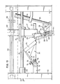
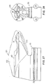
- the filleting machine represented in fig. 1 and 2 consists of a frame 1 with a pair of front legs 2 and a pair of rear legs 3.
- the frame is constructed from angle steel and comprises two side windows 4 and 5, a front window 6 and a rear window 7.
- side windows columns 8-11 are present which partly serve as stiffening and are partly used for supporting various parts to be illustrated later on.
- the frame provides a pivotable support for two chain wheel shafts 12 and 13 on which chain wheels 14 and 15 are disposed which determine the transitions between an upper part 16 and a lower part 17 of a chain conveyor drawn in dotted lines.
- the chain wheel shaft 13 may be driven by an electromotor 18 and in order to keep the tension of the chain 16/17 at the correct value the shaft 12 is slidable in an oblong hole 19 in longitudinal direction of the machine.
- a plurality of retaining means 20 is disposed on the chain conveyor 16/17 which in fig. 1 in the top part 16 of the machine move from the left to the right and in the lower part 17 from the right to the left. They will be illustrated with the aid of figures 3-5.
- a first centering device 21 is present next to and over the top part 16 of the conveyor which will be illustrated with the aid of figures 7-9.
- the retaining means both in the top part 16 and in the lower part 17 are guided by parallel uppermost and lowermost guide rod pairs 23 and 24 which fit in semicircular lateral recesses 25 on either side of the retaining means 20.
- the guiding rods are connected to the frame 1 by means of brackets 26.
- a tilting mechanism 28 (fig. 13 and 14) with centre block 29 (figures 11 and 12) for rolling off the uppermost muscle of the breast-bone from the carcass, and a filleting tunnel 30 (figures 15-17) for stripping the fillets from the carcass, are present next to and under the lower part 7 of the conveyor.
- a meat unloader 31 (fig. 18) and a meat catcher 32 (figures 19 and 20) are present which may be driven by a second electromotor 33.
- the retaining means 20 (figures 3-6)
- the retaining means 20 shows a cross-section configuration adapted to the interior of the carcass of the poultry and preferably consists of plastic material.
- the part on the right hand of the shoulder in figures 4 and 5 is essential for the invention.
- the longitudinal surfaces 35 bordering the shoulders 34 extend forwardly mutually parallelly and constitute near the end the outer surfaces of protrusions 36 which protrude outwardly through the carcass when retaining a carcass.
- These protrusions 36 have inner surfaces 37 extending obliguely towards each other with barbs 38 which engage just pass the wing joint bones 39 (figure 3) of the carcass when the carcass has been positioned far enough on the retaining means by hand or by the first centering device 21.
- the upper surface 40 of the retaining means 20 is recessed in such a way that near the foreward end of the retaining means 20 an upwardly directed cam 41 is formed which fits in a (not visible) cavity of the breast bone 42 of the carcass.
- the lower side of the protrusion has a recess 43 obtained by milling and also serving for receiving carcass portions.
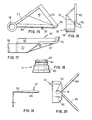
- Centering devices 21 and 27 mainly consist of a pair of side blocks 44 which are tiltable in transverse direction to the retaining means 20.
- the left-hand block drawn in continuous lines is in the position in which the fillet is fixedly positioned on the retaining means.
- Not drawn connecting means see to it that the side blocks immediately after having performed their function are swung to the position represented in dotted lines by the cylinders 45. After the remaining part of the retaining means 20 has been passed, they return in the position represented in continuous lines.
- the side blocks 44 are pivotably connected to supports 48 about shafts 47 which supports are fastened to the side windows 4 and 5 and by screws (not represented) to swivelling bars 46 the extremities of which are pivotably connected to piston rods 49 of the air cylinders 45 which themselves are supported on the supports 48 pivotably about axes 51.
- the side-blocks 44 In longitudinal and top view (figures 8 and 9) the side-blocks 44 have a centering plate 52 and the design of the centering surfaces 53 facing each other is attuned to the average appearance of the wing joint bones 39 (fig. 3) of the poultry. These centering surfaces also push the forked bones more inwardly and in result they can pass through the slot of the centre block 29.
- the second centering device 27 at the lower part 17 of the conveyor is of the same construction and operation as the above described first centering device, but it is of course upside down.
- the function of the first centering device was to prevent a carcass from falling from a retaining means; the object of the second centering device is making the carcass ready for the supply to the filleting tunnel 30.
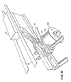
- an air cylinder 54 is fastened.
- the piston rod 55 of this cylinder is pivotably connected to one extremity of a lever 57 supported on the frame 1 by a shaft 56 and the other extremity of which is united to a centre block carrier 58 for the tiltable support of the centre block 29 for scraping the forked bone and stripping the normal upper muscle of the breast bone from the carcass, as well as loosening the outer fillets and the inner fillets.
- parts 54-58 constitute the tilting mechanism 28.
- the cylinders 45 and 54 of the second centering device 27 and the tilting mechanism 28 resp. are controlled by approximation switches 60 schematically represented on a beam 59 in fig. 10 so that the side blocks 44 and the centre block 29 are advanced almost simultaneously to the active position represented in fig. 10, but the side blocks are moved back to the inactive positions apparently earlier than the centre block 29.
- the metal centre block 29 has a back wall 61 to which a plastic slide plate 62 can be fastened which is wider than the back wall.
- a plastic slide plate 62 can be fastened to the centre block carrier 58 of the tilting mechanism 28 on one side of the connection with the lever 57 .
- two angle irons 63 are welded, in which the slide plate 62 can move rectilinearly, and on the other side of the connection with the lever 57 a support 64 with a hole 65 through which a centre block rod 66 (fig. 10) can slide in a reciprocable manner.
- a centre block rod 66 is present, so that the centre block 29 is supported to the tilting mechanism in a springing manner.
- the centre block 29 has two side walls 69 extending in longitudinal direction of the machine and having pointed fore-ends 70 which clean the forked bone and loosen the inner fillets. Thereinbetween an adjustable chisel 70' loosening the upper muscle is present. The leading edge of the pointed fore-parts loosen muscles attached to the wing joint bones. These muscles extend through the inner fillets. When they are not cut loose, loose inner fillets are obtained. Also centering cheeks 71 are applied, whose inner circumferences correspond to the appearance of the carcass still comprising fillets and which clean the bent gouge collar bone and therewith loosen the fillets.
- the filleting tunnel 30 (figures 10 and 15-17)
- the filleting tunnel halves 30 have horizontal inner edges 80 facing each other which are spaced that far that the breast bone of the carcass can pass between them.
- the side walls 81 are positioned so obliguely in respect of the moving direction of the retaining means 20 that the fillets when passing the retaining means through the filleting tunnel are more or less folded under the influence of these side walls, so pass along the outer edge of the side walls 81 but are still connected to the carcass.
- the access to the filleting tunnel is bounded by gate halves 82 which have, of course, such dimensions that the retaining means plus carcasses retained thereon can pass. After the filleting tunnel the fillets only stick to the breast bone.
- the meat unloader 31 (fig. 18)
- the meat unloader 31 consists of two cross cut ends 84 of stepped plastic bushes 85 having confronting teeths 83, which bushes can clockwise rotate when driven by a meat unloader chain 86 which is branched from the tooth wheel transmission 87 of the second electromotor 33 for driving a carcass remover 88, known per se.
- the meat catcher 32 (figures 1, 2 and 19, 20)
- the meat catcher 32 which consists of two divergent rods 89 and a meat catching supporting plate 90 with a slot 91 debouching into a relatively small hole 92.
- the incision device 22 (figures 21-23)
- Bearings 93 are applied to sides of the side windows 4 and 5 facing each other for pivotably supporting a shaft 94.
- a long lever arm 95 is attached to this shaft 94, which arm can be swung downwardly from a substantially upward position counter-clockwise by side strips 96 of the retaining means 20 in figure 22, and which can be swung back by a spring 97 after having passed the retaining means 20, a short lever arm 98 abutting a stop 99.
- Two upwardly directed protrusions 100 are supported on the shaft 94 and each carry on its free end a rod head 101 which are each, via a rod shaft 102, connected to another rod head 103 which are each pivotably connected to a knive carrier 103 pivotable about a shaft 104.
- the knife carriers 105 support the incision knives 106 which move exactly between the protrusions 36 of a retaining means 20 according arrow B of fig. 3 in the poultry and then cut meat loose from the carcass along circular sector paths, so that the meat yield per carcass becomes higher.
- the side strips 96 of the retaining means 20 could be omitted in case of a somewhat different position of the long lever arm 95, but may also serve to guarantee that the retaining means 20 get into the pairs of guide rods 23, 24 at the transitions between the upper part 16 and the lower part 17 and the other way round. At these transitions then a (not represented) bent guide strip can be applied which prevents the retaining means 20 from tilting laterally with regard to the chain conveyor.
- a conveyor belt may be applied for discharging, checking and packing the fillets. Since the conveyor belt in question is positioned preferably at a level above the floor on which the said acts can readily be performed, the lower part 16 of the conveyor will get at such a level above the floor that it turns out to be necessary to attach a platform to the legs 2 and 3, so that the machine can be loaded.
- half fillets can be made in an easier manner, because the halves are only connected to each other by a weak breast bone muscle and can readily get loosened from each other.
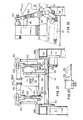
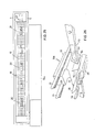
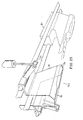
- the filleting machine represented in fig. 24 and 25 consists of a frame 1 with a pair of front legs 2 and a pair of rear legs 3.
- the frame is constructed from metallic tubular profiles and comprises two side windows 4 and 5 with columns 8-10 which partly serve as a stiffening and partly for supporting various parts of the machine to be illustrated later on.
- the frame provides a pivotable support for two chain wheel shafts 12 and 13 on which chain wheels 14 and 15 are applied which determine the transitions between an upper part 16 and a lower part 17 of a caterpillar conveyor with link plates 18.
- the chain wheel shaft 13 can be driven by an electromotor and in order to keep the tension of the caterpillar 16/17 at the correct value the shaft 12 is slidable in longitudinal direction of the machine.
- a plurality of retaining means 20 is applied to the conveyor 16-17 which in fig. 24 in the upper part 16 of the machine move from the left to the right and in the lower part 17 from the right to the left.
- the fellow-workers standing on a flight of steps put the carcasses onto the retaining means 20 moving in the upper part 16 and being illustrated with the aid of figures 27 and 28.
- the retaining means are additionally guided by guide bars 24.
- the incision device 108 with fixed knives (fig. 26)
- a tilting mechanism 28 (like figures 13 and 14) with centre block 29 (like figures 11 and 12) for rolling off the upper muscle from the breast bone of the carcass
- a tiltable filleting tunnel 109 (fig. 29) for stripping the fillets from the carcass, are present.
- a meat unloader 110 with pertaining catcher 111 (fig. 30) is present, the meat unloader being adapted to be driven by a second electromotor.
- a carcass remover is represented at 88.
- Fig. 24 showing the final design of the filleting machine has mainly the following differences with regard to figure 1.
- the first centering device 21 which was illustrated with the aid of figures 7-9 has been replaced and the same applies to the incision device 22 with moving knives 106 illustrated with the aid of figures 21-23.
- the final filleting machine comprises a breast guiding means 107 mainly consisting of two parallel bent rods, which serves both as a first centering device and as means for preventing the carcasses from being released, and an incision device 108 with fixed knives which will be illustrated with the aid of figure 26.
- the last-mentioned alteration otherwise also leads to an alteration of the retaining means 20 (fig. 27 and 28).
- the filleting tunnel 30 has been replaced by a tunnel 109 (fig. 29) with tunnel parts foldable about horizontal axes, so that carcasses having a broken bent gouge collar bone can be thrown off between times and it cannot be so that after a few seconds a following chicken collides with a jammed chicken.
- a depositing roller is applied, so that the fillets are spread on a (not represented) discharge conveyor belt by the new meat unloader 110 instead of, like with the prototype, on a heap.
- Incision device 108 (figure 26)
- An incision device 108 consists of two stationary knives 112 which at an angle of substantially 15° to the moving direction of the carcasses are applied to the ends of knife carriers 113 which are adjustably fastened to the columns 9 of the frame.
- This incision device provided it is well adjusted, a yield increase up to 100% (like by hand) is possible, because the knives with the sharp edge 114 remove a piece of meat being stuck with a web over the ribs. This web comes along as well, because actually it is rather stripping than cutting. Only the sharp edge 114 makes an incision, the remaining part of the leading edge is blunt and thereby tears the web loose further. This appears to be possible because the ribs are resilient.
- the retaining means 20 (fig. 27 and 28)
- a carcass 121 is shown with a breast 122 and a back part 123.
- the breast guiding means 107 it is no longer necessary for the retaining means to comprise barbs.
- the filleting tunnel 109 (fig. 29).
- the meat unloader 110 (fig. 30)
- a large roller 116 is disposed with an elevated edge 117 in the centre.
- the large roller draws the fillets when rotated in the direction of arrow 118 somewhat downwardly so that the outer fillets are slightly tensioned and are put down in a spreaded manner.
- the elevated edge 117 it is achieved that the inner fillets are not loaded and thereby remain connected to the outer fillets.
- the meat catcher 32 is positioned over the bushes 85 and the large roller 116 and directs the cam of the carcass between the bushes 85.
Landscapes
- Life Sciences & Earth Sciences (AREA)
- Engineering & Computer Science (AREA)
- Wood Science & Technology (AREA)
- Zoology (AREA)
- Food Science & Technology (AREA)
- Processing Of Meat And Fish (AREA)
- Butt Welding And Welding Of Specific Article (AREA)
- Drying Of Solid Materials (AREA)
Claims (7)
- Filetiervorrichtung zum Entfernen der Filets vom Körper eines ausgenommenen Geflügels, dessen Beine und Flügel bereits entfernt sind, bestehend aus einem Rahmen (1), in welchen ein antreibbarer Förderer (16, 17) befestigt ist, auf dem in regelmäßigen Abständen eine Anzahl von Rückhaltemitteln (20) vorgesehen ist, um das Geflügel durch eine Einschneidevorrichtung (22, 108) und durch ein in der unteren Bahn (17) des Förderers angeordnetes Torglied zu bewegen, um die Filets vom Körper zu schieben, Mittel (107), um zu gewährleisten, daß der Körper weiter verarbeitet wird, welche in der oberen Bahn (16) des Förderers auf die Rückhaltemittel (20) gesetzt sind und beim Übergang zur unteren Bahn (17) des Förderers auf dem Rückhaltemittel sitzen bleiben, und ein Mechanismus (28), der eine federbeaufschlagte (68) Mittensperrung (29) zum Abrollen des oberen Muskels vom Brustbein (42) des Körpers, welcher Mechanismus (28) kippbar ist um eine horizontale Achse (56) zwischen dem Torglied (30) und der Einschneidevorrichtung (22, 108).
- Vorrichtung nach Anspruch 1 , dadurch gekennzeichnet, daß ein Paar von Seitensperrungen (44) gegeneinander beweglich ist in einer Richtung im wesentlichen quer zur Maschine, um die Flügelgelenkknochen (39) des Körpers unmittelbar vor dem Torglied (30) gegeneinander zu pressen.
- Vorrichtung nach Anspruch 1 oder 2, dadurch gekennzeichnet, daß die Rückhaltemittel (20) mit zwei in Draufsicht vorwärts gerichteten Vorsprüngen (36) versehen sind, mit äußeren Oberflächen, die mit den längslaufenden Oberflächen (34) der Rückhaltemittel (20) überein-stimmend angeordnet sind, und mit widerhakenden, schrägen inneren Oberflächen (37), wobei ein aufwärts gerichteter und nach vorne spitzer Nocken (41) an der Stelle vorgesehen ist, an der die schrägen inneren Oberflächen (37) verbunden sind.
- Vorrichtung nach einem der vorhergehenden Ansprüche, dadurch gekennzeichent, daß die Einschneidevorrichtung (22) mit zwei Einschnittsmessern (106) vorgesehen ist, welche Fleisch von dem Körper exakt zwischen den Vorsprüngen (36) des Rückhaltemittels (20) entlang einem abwärts kreisförmigen Sektorweg losschneiden, welcher quer zu einer Längserstreckungsrichtung der Vorrichtung verläuft.
- Vorrichtung nach Anspruch 4, dadurch gekennzeichnet, daß Messerhalter (105) der Einschneidemesser (106) antreibbar sind durch die Rückhaltemittel (20) über ein Hebelsystem (95, 100 bis 104) und rückstellbar mittels einer Feder (97).
- Vorrichtung nach einem der Ansprüche 1 bis 3, dadurch gekennzeichnet, daß die Einschneidevorrichtung (108) aus zwei feststehenden Messern (112) bestehend, welche mit einem Winkel von etwa 15° zur Bewegungsrichtung des Körpers an den Enden von Messerhaltern (113) in einstellbarer Weise am Rahmen (1) angebracht sind, während die Rückhaltemittel korrespondierende Aussparungen (115) haben.
- Vorrichtung nach Anspruch 6, dadurch gekennzeichnet, daß der Förderer eine Raupe (16, 17) ist und daß das Torglied aus zwei Tunnelhälften (30) besteht, welche um horizontale Achsen (73) klappbar sind.
Priority Applications (1)
| Application Number | Priority Date | Filing Date | Title |
|---|---|---|---|
| AT86201063T ATE63422T1 (de) | 1985-06-18 | 1986-06-18 | Vorrichtung zum filetieren. |
Applications Claiming Priority (2)
| Application Number | Priority Date | Filing Date | Title |
|---|---|---|---|
| NL8501748 | 1985-06-18 | ||
| NL8501748A NL8501748A (nl) | 1985-06-18 | 1985-06-18 | Fileermachine. |
Publications (2)
| Publication Number | Publication Date |
|---|---|
| EP0207553A1 EP0207553A1 (de) | 1987-01-07 |
| EP0207553B1 true EP0207553B1 (de) | 1991-05-15 |
Family
ID=19846158
Family Applications (1)
| Application Number | Title | Priority Date | Filing Date |
|---|---|---|---|
| EP86201063A Expired - Lifetime EP0207553B1 (de) | 1985-06-18 | 1986-06-18 | Vorrichtung zum Filetieren |
Country Status (4)
| Country | Link |
|---|---|
| EP (1) | EP0207553B1 (de) |
| AT (1) | ATE63422T1 (de) |
| DE (1) | DE3679243D1 (de) |
| NL (1) | NL8501748A (de) |
Families Citing this family (13)
| Publication number | Priority date | Publication date | Assignee | Title |
|---|---|---|---|---|
| NL8601921A (nl) * | 1986-07-24 | 1988-02-16 | Stork Pmt | Opzetsteun. |
| DE3811317A1 (de) * | 1988-04-02 | 1989-10-19 | Nordischer Maschinenbau | Verfahren zum gewinnen des fleisches von den koerpern geschlachteten gefluegels und vorrichtung zur durchfuehrung des verfahrens |
| ATE79516T1 (de) * | 1989-01-28 | 1992-09-15 | Nordischer Maschinenbau | Verfahren zum maschinellen gewinnen des fleisches von gefluegelkoerpern und vorrichtung zur durchfuehrung des verfahrens. |
| DE3918345A1 (de) * | 1989-06-06 | 1990-12-13 | Nordischer Maschinenbau | Haltevorrichtung zur halterung von gefluegelkoerpern waehrend deren bearbeitung |
| DE3939340C1 (de) * | 1989-11-29 | 1991-06-06 | Nordischer Maschinenbau Rud. Baader Gmbh + Co Kg, 2400 Luebeck, De | |
| US5045022A (en) * | 1990-01-31 | 1991-09-03 | Hazenbroek Jacobus E | Adjustable poultry breast filleting system |
| DE4008719A1 (de) * | 1990-03-19 | 1991-09-26 | Nordischer Maschinenbau | Verfahren zum filetieren von gefluegelkoerpern |
| DE4234040C2 (de) * | 1992-10-09 | 1997-05-22 | Nordischer Maschinenbau | Verfahren zum maschinellen Gewinnen des Fleisches von Geflügelkörpern und Einrichtung zur Durchführung des Verfahrens |
| NL1001281C2 (nl) * | 1995-09-26 | 1997-03-28 | Meyn Maschf | Werkwijze en inrichting voor het fileren van het borststuk van gevogelte. |
| DE19848498A1 (de) | 1998-10-21 | 2000-05-04 | Nordischer Maschinenbau | Filetiervorrichtung |
| NL1027426C2 (nl) * | 2004-11-05 | 2006-05-15 | Systemate Group Bv | Fileermachine voor gevogelte. |
| NL2011718C2 (en) | 2013-11-01 | 2015-05-04 | Foodmate B V | Method and system for automatically deboning poultry breast caps containing meat and a skeletal structure to obtain breast fillets therefrom. |
| DE102020108618A1 (de) * | 2020-03-27 | 2021-09-30 | Nordischer Maschinenbau Rud. Baader Gmbh + Co. Kg | Halteelement zum Anordnen von Rückenteilen oder Teilen davon von Geflügelschlachtkörpern |
Family Cites Families (6)
| Publication number | Priority date | Publication date | Assignee | Title |
|---|---|---|---|---|
| US455017A (en) * | 1891-06-30 | Carpet-beating machine | ||
| DE2110080A1 (en) * | 1971-03-03 | 1972-09-21 | Poultry filleter - with hand operated knife contoured to shape of poultry breast | |
| US4385419A (en) * | 1982-03-15 | 1983-05-31 | Cantrell Machine Co., Inc. | Chicken deboning apparatus and method |
| NL8300907A (nl) * | 1983-03-11 | 1984-10-01 | Stork Pmt | Inrichting voor het afscheiden van de vleesdelen van het borststuk van geslacht gevogelte. |
| NL8302494A (nl) * | 1983-07-13 | 1985-02-01 | Systemate Bv | Fileermachine. |
| NL8402165A (nl) * | 1984-07-06 | 1986-02-03 | Meyn Pieter | Werkwijze en inrichting voor het verwijderen van borstvlees van een gevogeltekarkas. |
-
1985
- 1985-06-18 NL NL8501748A patent/NL8501748A/nl not_active Application Discontinuation
-
1986
- 1986-06-18 DE DE8686201063T patent/DE3679243D1/de not_active Expired - Fee Related
- 1986-06-18 AT AT86201063T patent/ATE63422T1/de not_active IP Right Cessation
- 1986-06-18 EP EP86201063A patent/EP0207553B1/de not_active Expired - Lifetime
Also Published As
| Publication number | Publication date |
|---|---|
| DE3679243D1 (de) | 1991-06-20 |
| NL8501748A (nl) | 1987-01-16 |
| EP0207553A1 (de) | 1987-01-07 |
| ATE63422T1 (de) | 1991-06-15 |
Similar Documents
| Publication | Publication Date | Title |
|---|---|---|
| EP0207553B1 (de) | Vorrichtung zum Filetieren | |
| DE69630178T2 (de) | Verfahren und Vorrichtung zum Bearbeiten von Schlachtgeflügel | |
| EP0440032B1 (de) | Einstellbares System zum Filettieren von Geflügelbrust | |
| US4648156A (en) | Method and apparatus for removing the breast flesh from a poultry carcass | |
| EP0508551B1 (de) | Vorrichtung zum automatischen Spalten von Schlachttierkörpern | |
| EP0054060B1 (de) | Geflügelschneidevorrichtung | |
| CA2418338C (en) | Dual blade loin knife assembly for automatic loin puller apparatus | |
| DE69112280T2 (de) | Verfahren und Vorrichtung zum Abtrennen der Beine von Schlachtgeflügel-Körperstücken. | |
| CA2008386C (en) | Adjustable poultry carcass separator | |
| US6322438B1 (en) | Poultry leg and thigh processor | |
| JP3431196B2 (ja) | 屠殺された鳥の胴体を切身にするための方法と装置 | |
| US5188560A (en) | Wing tip cutter | |
| US5080630A (en) | Poultry processing apparatus and method | |
| US5697837A (en) | Poultry breast filleting apparatus | |
| US6656032B2 (en) | Leg part cutter | |
| EP1654932B2 (de) | Maschine zum Filetieren von Geflügel | |
| NL9200111A (nl) | Werkwijze en inrichting voor het uitbenen van middels van slachtdieren. | |
| US5466185A (en) | Removing breast meat from poultry | |
| US4270243A (en) | Poultry breast splitting apparatus | |
| JPH0156734B2 (de) | ||
| US4648155A (en) | Chicken deboning apparatus and method | |
| US8342919B1 (en) | Method and apparatus for cutting the second joint of a poultry wing and product therefrom | |
| US4073041A (en) | Crab butchering machine | |
| EP0310713A1 (de) | Verfahren und Vorrichtung zum Durchschneiden von geschlachtetem Geflügel | |
| US5494480A (en) | Method and device for boning abdominal sections, containing spinal parts, of animals for slaughter |
Legal Events
| Date | Code | Title | Description |
|---|---|---|---|
| PUAI | Public reference made under article 153(3) epc to a published international application that has entered the european phase |
Free format text: ORIGINAL CODE: 0009012 |
|
| AK | Designated contracting states |
Kind code of ref document: A1 Designated state(s): AT BE CH DE FR GB IT LI LU NL SE |
|
| 17P | Request for examination filed |
Effective date: 19870514 |
|
| 17Q | First examination report despatched |
Effective date: 19890306 |
|
| GRAA | (expected) grant |
Free format text: ORIGINAL CODE: 0009210 |
|
| AK | Designated contracting states |
Kind code of ref document: B1 Designated state(s): AT BE CH DE FR GB IT LI LU NL SE |
|
| REF | Corresponds to: |
Ref document number: 63422 Country of ref document: AT Date of ref document: 19910615 Kind code of ref document: T |
|
| ITF | It: translation for a ep patent filed | ||
| REF | Corresponds to: |
Ref document number: 3679243 Country of ref document: DE Date of ref document: 19910620 |
|
| ET | Fr: translation filed | ||
| PLBE | No opposition filed within time limit |
Free format text: ORIGINAL CODE: 0009261 |
|
| STAA | Information on the status of an ep patent application or granted ep patent |
Free format text: STATUS: NO OPPOSITION FILED WITHIN TIME LIMIT |
|
| 26N | No opposition filed | ||
| EPTA | Lu: last paid annual fee | ||
| EAL | Se: european patent in force in sweden |
Ref document number: 86201063.4 |
|
| PGFP | Annual fee paid to national office [announced via postgrant information from national office to epo] |
Ref country code: LU Payment date: 19950601 Year of fee payment: 10 |
|
| PGFP | Annual fee paid to national office [announced via postgrant information from national office to epo] |
Ref country code: GB Payment date: 19960610 Year of fee payment: 11 |
|
| PGFP | Annual fee paid to national office [announced via postgrant information from national office to epo] |
Ref country code: FR Payment date: 19960613 Year of fee payment: 11 |
|
| PGFP | Annual fee paid to national office [announced via postgrant information from national office to epo] |
Ref country code: SE Payment date: 19960614 Year of fee payment: 11 |
|
| PG25 | Lapsed in a contracting state [announced via postgrant information from national office to epo] |
Ref country code: LU Free format text: LAPSE BECAUSE OF NON-PAYMENT OF DUE FEES Effective date: 19960618 |
|
| PGFP | Annual fee paid to national office [announced via postgrant information from national office to epo] |
Ref country code: AT Payment date: 19960628 Year of fee payment: 11 |
|
| PGFP | Annual fee paid to national office [announced via postgrant information from national office to epo] |
Ref country code: NL Payment date: 19960630 Year of fee payment: 11 |
|
| PGFP | Annual fee paid to national office [announced via postgrant information from national office to epo] |
Ref country code: CH Payment date: 19960702 Year of fee payment: 11 |
|
| PGFP | Annual fee paid to national office [announced via postgrant information from national office to epo] |
Ref country code: DE Payment date: 19960705 Year of fee payment: 11 |
|
| PGFP | Annual fee paid to national office [announced via postgrant information from national office to epo] |
Ref country code: BE Payment date: 19960711 Year of fee payment: 11 |
|
| PG25 | Lapsed in a contracting state [announced via postgrant information from national office to epo] |
Ref country code: GB Free format text: LAPSE BECAUSE OF NON-PAYMENT OF DUE FEES Effective date: 19970618 Ref country code: AT Effective date: 19970618 |
|
| PG25 | Lapsed in a contracting state [announced via postgrant information from national office to epo] |
Ref country code: SE Effective date: 19970619 |
|
| PG25 | Lapsed in a contracting state [announced via postgrant information from national office to epo] |
Ref country code: LI Free format text: LAPSE BECAUSE OF NON-PAYMENT OF DUE FEES Effective date: 19970630 Ref country code: CH Free format text: LAPSE BECAUSE OF NON-PAYMENT OF DUE FEES Effective date: 19970630 Ref country code: BE Effective date: 19970630 |
|
| BERE | Be: lapsed |
Owner name: SYSTEMATE HOLLAND B.V. Effective date: 19970630 |
|
| PG25 | Lapsed in a contracting state [announced via postgrant information from national office to epo] |
Ref country code: NL Effective date: 19980101 |
|
| GBPC | Gb: european patent ceased through non-payment of renewal fee |
Effective date: 19970618 |
|
| REG | Reference to a national code |
Ref country code: CH Ref legal event code: PL |
|
| PG25 | Lapsed in a contracting state [announced via postgrant information from national office to epo] |
Ref country code: FR Free format text: LAPSE BECAUSE OF NON-PAYMENT OF DUE FEES Effective date: 19980227 |
|
| EUG | Se: european patent has lapsed |
Ref document number: 86201063.4 |
|
| NLV4 | Nl: lapsed or anulled due to non-payment of the annual fee |
Effective date: 19980101 |
|
| PG25 | Lapsed in a contracting state [announced via postgrant information from national office to epo] |
Ref country code: DE Free format text: LAPSE BECAUSE OF NON-PAYMENT OF DUE FEES Effective date: 19980303 |
|
| REG | Reference to a national code |
Ref country code: FR Ref legal event code: ST |
|
| REG | Reference to a national code |
Ref country code: FR Ref legal event code: ST |
|
| PG25 | Lapsed in a contracting state [announced via postgrant information from national office to epo] |
Ref country code: IT Free format text: LAPSE BECAUSE OF NON-PAYMENT OF DUE FEES;WARNING: LAPSES OF ITALIAN PATENTS WITH EFFECTIVE DATE BEFORE 2007 MAY HAVE OCCURRED AT ANY TIME BEFORE 2007. THE CORRECT EFFECTIVE DATE MAY BE DIFFERENT FROM THE ONE RECORDED. Effective date: 20050618 |