EP0207048A1 - Charging equipment for a shaft furnace for burning mineral materials containing carbonates - Google Patents
Charging equipment for a shaft furnace for burning mineral materials containing carbonates Download PDFInfo
- Publication number
- EP0207048A1 EP0207048A1 EP86890057A EP86890057A EP0207048A1 EP 0207048 A1 EP0207048 A1 EP 0207048A1 EP 86890057 A EP86890057 A EP 86890057A EP 86890057 A EP86890057 A EP 86890057A EP 0207048 A1 EP0207048 A1 EP 0207048A1
- Authority
- EP
- European Patent Office
- Prior art keywords
- closure
- loading container
- loading
- shafts
- shaft
- Prior art date
- Legal status (The legal status is an assumption and is not a legal conclusion. Google has not performed a legal analysis and makes no representation as to the accuracy of the status listed.)
- Granted
Links
- 229910052500 inorganic mineral Inorganic materials 0.000 title claims abstract description 4
- 239000011707 mineral Substances 0.000 title claims abstract description 4
- 239000000463 material Substances 0.000 title claims description 19
- 150000004649 carbonic acid derivatives Chemical class 0.000 title 1
- BVKZGUZCCUSVTD-UHFFFAOYSA-L Carbonate Chemical compound [O-]C([O-])=O BVKZGUZCCUSVTD-UHFFFAOYSA-L 0.000 claims abstract description 3
- 238000007789 sealing Methods 0.000 claims description 9
- 239000000446 fuel Substances 0.000 abstract description 4
- 238000010276 construction Methods 0.000 abstract 1
- 238000010304 firing Methods 0.000 description 8
- 239000002737 fuel gas Substances 0.000 description 2
- 239000000567 combustion gas Substances 0.000 description 1
- 230000007812 deficiency Effects 0.000 description 1
- 230000000694 effects Effects 0.000 description 1
Images


Classifications
-
- C—CHEMISTRY; METALLURGY
- C21—METALLURGY OF IRON
- C21C—PROCESSING OF PIG-IRON, e.g. REFINING, MANUFACTURE OF WROUGHT-IRON OR STEEL; TREATMENT IN MOLTEN STATE OF FERROUS ALLOYS
- C21C7/00—Treating molten ferrous alloys, e.g. steel, not covered by groups C21C1/00 - C21C5/00
-
- C—CHEMISTRY; METALLURGY
- C04—CEMENTS; CONCRETE; ARTIFICIAL STONE; CERAMICS; REFRACTORIES
- C04B—LIME, MAGNESIA; SLAG; CEMENTS; COMPOSITIONS THEREOF, e.g. MORTARS, CONCRETE OR LIKE BUILDING MATERIALS; ARTIFICIAL STONE; CERAMICS; REFRACTORIES; TREATMENT OF NATURAL STONE
- C04B2/00—Lime, magnesia or dolomite
- C04B2/10—Preheating, burning calcining or cooling
- C04B2/12—Preheating, burning calcining or cooling in shaft or vertical furnaces
-
- F—MECHANICAL ENGINEERING; LIGHTING; HEATING; WEAPONS; BLASTING
- F27—FURNACES; KILNS; OVENS; RETORTS
- F27B—FURNACES, KILNS, OVENS, OR RETORTS IN GENERAL; OPEN SINTERING OR LIKE APPARATUS
- F27B1/00—Shaft or like vertical or substantially vertical furnaces
- F27B1/02—Shaft or like vertical or substantially vertical furnaces with two or more shafts or chambers, e.g. multi-storey
- F27B1/04—Combinations or arrangements of shafts
-
- F—MECHANICAL ENGINEERING; LIGHTING; HEATING; WEAPONS; BLASTING
- F27—FURNACES; KILNS; OVENS; RETORTS
- F27B—FURNACES, KILNS, OVENS, OR RETORTS IN GENERAL; OPEN SINTERING OR LIKE APPARATUS
- F27B1/00—Shaft or like vertical or substantially vertical furnaces
- F27B1/10—Details, accessories, or equipment peculiar to furnaces of these types
- F27B1/20—Arrangements of devices for charging
Definitions
- the invention relates to a loading device for a shaft furnace for burning carbonate-containing, mineral combustible material in at least two shafts, consisting of a common loading container which is connected to the shafts via a feed line in each case.
- pressure locks must be provided between the common loading container and the individual shafts, which increase the necessary overall height.
- These pressure locks consist, for example, of a closure flap for the individual shafts and from these closure flaps downstream bell closures.
- the metered amount of firing material that has been fed into the loading container must therefore be introduced into the shaft space between the closure flap and the bell closure via the associated conveyor tube when the closure flap is open, before the bell closure can be opened after the closure flap has been closed. Since the material to be fired rests on the bell of the bell closure, the sealing surface is acted upon by the material to be fired, which results in unfavorable loading conditions.
- the invention is therefore based on the object of avoiding these deficiencies and improving a loading device of the type described at the outset in such a way that the necessary overall height for the loading device can be reduced while ensuring a simple, gas-tight shaft closure.
- the invention achieves the stated object in that the loading container is designed as a lock chamber, each with a lock closure for the inlet opening of the loading container and for the connection openings of the feed lines.
- the design of the loading container itself as a lock chamber eliminates the need to arrange a lock chamber for the feed container, so that the overall height of the loading device can be reduced by the height of conventional lock chambers.
- the use of the loading container as a lock chamber not only brings about an increase in overall height, but also a design simplification, since a separate lock chamber does not have to be assigned to each shaft. Since in order to load a shaft with the metered amount of firing material introduced into the loading container, only the lock closure for the connection opening of the feed line has to be opened in order to be able to enter the goods into the shaft via the feed line there is also the advantage of simplified control.
- the lock closures each consist of a closure flap provided on the outlet side of the inlet or connection opening, which in the closed position overlaps a projecting edge collar of the inlet or connection opening with a sealing collar, it can be acted upon with simple means the sealing surfaces can be avoided by the firing material.
- the sealing surfaces are located outside the edge collar, which projects against the closure flap and prevents the material to be penetrated from the sealing surfaces. Long service lives can therefore be expected.
- the closure flaps can finally be openable via swivel arms which act on the closure flaps in a pivotally limited manner in the pivoting direction and actuate a pressure compensation valve in the closure flap. Since the swivel arms can be moved with limited stops relative to the closure flaps, the resulting idle stroke of the swivel arms can be used to actuate a pressure compensation valve provided in the closure flap. If the swivel arm is thus rotated from the closed position in the opening direction, the pressure compensation valve is first opened via the swivel arm before the swivel arm can engage the closure flap and open it after the idle stroke has been overcome. With the inevitable actuation of the pressure compensation valve before opening a lock, very low actuation forces are necessary.
- a loading container 3 which is connected to the shafts 1 and 2 via two feed lines 4 and 5.
- the fired material introduced into the feed container 3 can therefore be fed alternately to the shafts 1 and 2.
- a feeder (not shown for reasons of clarity) is used to load the container 3, which discharges the firing material into the loading container via an inlet opening 6.
- the loading container 3 is designed as a lock chamber, closures 8 being provided in the region of the inlet opening 6 of the loading container and in the region of the connection openings 7 for the feed lines 4 and 5.
- these lock closures each consist of a closure flap 9 to which a pivot lever 10 engages. This pivot lever sits on an actuating shaft 11 which can be rotated by means of a working cylinder 12 via an adjusting lever 13, as is indicated in FIG. 1.
- the arrangement is such that the swivel arm 10 engages with a bearing pin 14 in an elongated hole 15 of a bearing block 16 on the closure flap 9, so that when the swivel arm 10 is rotated about the actuating shaft 11, the swivel arm 10 has an idle stroke to the extent of that by Elongated hole 15 given game runs before the shutter 9 can be opened.
- This idle stroke is used to actuate a pressure compensation valve 17, which is provided in the closure flap 9 and can be opened via an extension lever 18 of the swivel arm 10.
- valve body is connected to the extension lever 18 of the swivel arm 10 for this purpose.
- the swivel arm 10 is actuated via the associated working cylinder 12, the actuating lever 13 and the actuating shaft 11, the pressure compensation valve 17 being opened in a first section, so that between the charging container 3 and the shaft 2 can set a pressure equalization.
- the shutter 9 is opened in a second section.
- the open position is indicated by dash-dotted lines.
- the closure flaps 9 provided on the outlet side of the respective opening 6 or 7 have a sealing collar 19 with which they overlap an edge collar 20 of the inlet opening 6 or the connection opening 7. Since the edge collar 20 protrudes toward the closure flap 9 and is overlapped by the sealing collar 19 of the closure flap 9, the seals 21 for the closure flaps 9 do not come into contact with the material to be burned, which has an advantageous effect on the service life.
- the shafts 1 and 2 are alternately connected to a fresh air line 23 and an exhaust line 24 via a switching device 22, so that the fuel gases pass from the shaft connected to the fresh air channel 23, for example shaft 1, into the other shaft 2 via an overflow channel (not shown) and there can preheat the firing material in countercurrent before they escape from this shaft 2 via the exhaust line 24.
- the switchover device 22 After the switchover device 22 has been switched over, fuel and fresh air are supplied to the shaft 2 previously heated in countercurrent with the combustion gases from the other shaft 1, the fuel gases being passed through the shaft 2 in co-current with the fuel in order to now carry the fuel in the other shaft 1 warm up in countercurrent.
- the loading of the two shafts with firing material can take place either during counter-current operation or during direct-current operation.
Landscapes
- Engineering & Computer Science (AREA)
- Chemical & Material Sciences (AREA)
- Mechanical Engineering (AREA)
- General Engineering & Computer Science (AREA)
- Ceramic Engineering (AREA)
- Organic Chemistry (AREA)
- Materials Engineering (AREA)
- Thermal Sciences (AREA)
- Structural Engineering (AREA)
- Physics & Mathematics (AREA)
- Metallurgy (AREA)
- Furnace Details (AREA)
- Filling Or Emptying Of Bunkers, Hoppers, And Tanks (AREA)
- Furnace Charging Or Discharging (AREA)
- Vertical, Hearth, Or Arc Furnaces (AREA)
Abstract
Die Beschickungsvorrichtung für einen Schachtofen zum Brennen von karbonathaltigem, mineralischem Brenngut in zwei Schächten (1, 2) besteht aus einem gemeinsamen Beschickungsbehälter (3), der über je eine Aufgabeleitung (4, 5) an die Schächte (1, 2) angeschlossen ist. Um einfache Konstruktionsverhältnisse sicherzustellen und Bauhöhe zu gewinnen, ist der Beschickungsbehälter (3) als Schleusenkammer mit je einem Schleusenverschluss (8) für die Einlassöffnung (6) des Beschickungsbehälters (3) und für die Anschlussöffnungen (7) der Aufgabeleitungen (4, 5) ausgebildet.The loading device for a shaft furnace for burning carbonate-containing, mineral fuel in two shafts (1, 2) consists of a common loading container (3), which is connected to the shafts (1, 2) via a feed line (4, 5). In order to ensure simple construction conditions and to gain height, the loading container (3) is designed as a lock chamber, each with a lock closure (8) for the inlet opening (6) of the loading container (3) and for the connection openings (7) of the feed lines (4, 5) .
Description
Die Erfindung bezieht sich auf eine Beschickungsvorrichtung für einen Schachtofen zum Brennen von karbonathaltigem, mineralischem Brenngut in wenigstens zwei Schächten, bestehend aus einem gemeinsamen Beschickungsbehälter, der über je eine Aufgabeleitung an die Schächte angeschlossen ist.The invention relates to a loading device for a shaft furnace for burning carbonate-containing, mineral combustible material in at least two shafts, consisting of a common loading container which is connected to the shafts via a feed line in each case.
Bei einer bekannten Vorrichtung dieser Art (AT-PS 377 078) sind zwischen dem gemeinsamen Beschickungsbehälter und den abwechselnd mit Brenngut beschickbaren Schächten des Schachtofens Förderrohre vorgesehen, durch die das Brenngut aus dem Beschickungsbehälter dem jeweiligen Schacht zugeführt wird. Da diesem Behälter eine Dosiereinrichtung zugeordnet ist, die die Beschickung mit einer vorgegebenen Brenngutmenge sicherstellt, weist eine solche Vorrichtung gegenüber Beschickungsanlagen mit je einem Beschickungsbehälter für jeden Schacht den Vorteil auf, daß alle Schächte in einfacher Weise mit gleichen Gutmengen beschickt werden, weil sich nicht zufolge gesonderter Dosiereinrichtungen für jeden Schacht unterschiedliche Bemessungen ergeben können. Außerdem kann der Konstruktionsaufwand entsprechend gering gehalten werden. Trotz dieser Vorteile bleibt jedoch der Nachteil bestehen, daß wegen der Forderung nach einem gasdichten Schachtabschluß zwischen dem gemeinsamen Beschickungsbehälter und den einzelnen Schächten Druckschleusen vorgesehen werden müssen, die die notwendige Bauhöhe vergrößern. Diese Druckschleusen bestehen beispielsweise aus einer Verschlußklappe für die einzelnen Schächte und aus diesen Verschlußklappen nachgeordneten Glockenverschlüssen. Zur Beschickung eines Schachtes muß folglich die dem Beschickungsbehälter aufgegebene, dosierte Brenngutmenge über das zugehörige Förderrohr bei geöffneter Verschlußklappe in den Schachtraum zwischen Verschlußklappe und Glockenverschluß eingebracht werden, bevor nach einem Schließen der Verschlußklappe der Glockenverschluß geöffnet werden kann. Da das Brenngut auf der Verschlußglocke des Glockenverschlusses aufruht, wird die Dichtfläche durch das Brenngut beaufschlagt, was ungünstige Belastungsverhältnisse mit sich bringt.In a known device of this type (AT-PS 377 078) conveyor pipes are provided between the common loading container and the shafts of the shaft furnace which can be alternately loaded with firing material, through which the firing material is fed from the loading container to the respective shaft. Since this container is assigned a metering device which ensures the loading with a predetermined amount of combustible material, such a device has the advantage over loading systems with one loading container for each shaft that all shafts are loaded with the same quantities of material in a simple manner, because they do not follow one another separate metering devices can result in different dimensions for each shaft. In addition, the design effort can be kept correspondingly low. Despite these advantages, however, there remains the disadvantage that, because of the requirement for a gas-tight shaft closure, pressure locks must be provided between the common loading container and the individual shafts, which increase the necessary overall height. These pressure locks consist, for example, of a closure flap for the individual shafts and from these closure flaps downstream bell closures. To load a shaft, the metered amount of firing material that has been fed into the loading container must therefore be introduced into the shaft space between the closure flap and the bell closure via the associated conveyor tube when the closure flap is open, before the bell closure can be opened after the closure flap has been closed. Since the material to be fired rests on the bell of the bell closure, the sealing surface is acted upon by the material to be fired, which results in unfavorable loading conditions.
Der Erfindung liegt somit die Aufgabe zugrunde, diese Mängel zu vermeiden und eine Beschickungsvorrichtung der eingangs geschilderten Art so zu verbessern, daß unter Sicherstellung eines einfachen, gasdichten Schachtabschlusses die notwendige Bauhöhe für die Beschickungsvorrichtung herabgesetzt werden kann.The invention is therefore based on the object of avoiding these deficiencies and improving a loading device of the type described at the outset in such a way that the necessary overall height for the loading device can be reduced while ensuring a simple, gas-tight shaft closure.
Die Erfindung löst die gestellte Aufgabe dadurch, daß der Beschickungsbehälter als Schleusenkammer mit je einem Schleusenverschluß für die Einlaßöffnung des Beschickungsbehälters und für die Anschlußöffnungen der Aufgabeleitungen ausgebildet ist.The invention achieves the stated object in that the loading container is designed as a lock chamber, each with a lock closure for the inlet opening of the loading container and for the connection openings of the feed lines.
Durch die Ausbildung des Beschickungsbehälters selbst als Schleusenkammer entfällt die Notwendigkeit dem Beschickungsbehälter eine Schleusenkammer nachzuordnen, so daß-die Bauhöhe der Beschickungsvorrichtung um die Höhe üblicher Schleusenkammern verringert werden kann. Die Verwendung des Beschickungsbehälters als Schleusenkammer bringt jedoch nicht nur einen Gewinn an Bauhöhe, sondern auch eine Konstruktionsvereinfachung mit sich, weil nicht jedem Schacht eine gesonderte Schleusenkammer zugeordnet werden muß. Da zur Beschickung eines Schachtes mit der in den Beschickungsbehälter eingebrachten, dosierten Brenngutmenge lediglich der Schleusenverschluß für die Anschlußöffnung der Aufgabeleitung geöffnet werden muß, um das Gut über die Aufgabeleitung in den Schacht eintragen zu können, ergibt sich außerdem der Vorteil einer vereinfachten Steuerung.The design of the loading container itself as a lock chamber eliminates the need to arrange a lock chamber for the feed container, so that the overall height of the loading device can be reduced by the height of conventional lock chambers. However, the use of the loading container as a lock chamber not only brings about an increase in overall height, but also a design simplification, since a separate lock chamber does not have to be assigned to each shaft. Since in order to load a shaft with the metered amount of firing material introduced into the loading container, only the lock closure for the connection opening of the feed line has to be opened in order to be able to enter the goods into the shaft via the feed line there is also the advantage of simplified control.
Bestehen die Schleusenverschlüsse in weiterer Ausbildung der Erfindung aus je einer an der Austrittsseite der Einlaß- bzw. der Anschlußöffnung vorgesehenen Verschlußklappe, die in der Schließstellung einen vorragenden Randkragen der Einlaß- bzw. der Anschlußöffnung mit einem Dichtungskragen übergreift, so kann mit einfachen Mitteln eine Beaufschlagung der Dichtungsflächen durch das Brenngut vermieden werden. Die Dichtungsflächen befinden sich ja außerhalb des Randkragens, der gegen die Verschlußklappe vorsteht und ein Vordringen des Brenngutes zu den Dichtungsflächen verhindert. Es kann folglich mit hohen Standzeiten gerechnet werden.If, in a further embodiment of the invention, the lock closures each consist of a closure flap provided on the outlet side of the inlet or connection opening, which in the closed position overlaps a projecting edge collar of the inlet or connection opening with a sealing collar, it can be acted upon with simple means the sealing surfaces can be avoided by the firing material. The sealing surfaces are located outside the edge collar, which projects against the closure flap and prevents the material to be penetrated from the sealing surfaces. Long service lives can therefore be expected.
Um in einfacher Weise zum Öffnen der Verschlußklappe einen Druckausgleich herstellen zu können, können schließlich die Verschlußklappen über Schwenkarme öffenbar sein, die an den Verschlußklappen in Schwenkrichtung anschlagbegrenzt verschiebbar angreifen und ein Druckausgleichsventil in der Verschlußklappe betätigen. Da die Schwenkarme gegenüber den Verschlußklappen anschlagbegrenzt verschiebbar sind, kann der dadurch bedingte Leerhub der Schwenkarme zum Betätigen eines in der Verschlußklappe vorgesehenen Druckausgleichsventiles ausgenützt werden. Wird somit der Schwenkarm aus der Schließstellung im Öffnungssinn verdreht, so wird über den Schwenkarm zunächst das Druckausgleichsventil geöffnet, bevor nach dem Überwinden des Leerhubes der Schwenkarm an der Verschlußklappe angreifen und diese öffnen kann. Mit dem zwangsläufigen Betätigen des Druckausgleichsventiles vor dem Öffnen eines Schleusenverschlusses werden somit sehr geringe Betätigungskräfte notwendig.In order to be able to produce a pressure equalization in a simple manner for opening the closure flap, the closure flaps can finally be openable via swivel arms which act on the closure flaps in a pivotally limited manner in the pivoting direction and actuate a pressure compensation valve in the closure flap. Since the swivel arms can be moved with limited stops relative to the closure flaps, the resulting idle stroke of the swivel arms can be used to actuate a pressure compensation valve provided in the closure flap. If the swivel arm is thus rotated from the closed position in the opening direction, the pressure compensation valve is first opened via the swivel arm before the swivel arm can engage the closure flap and open it after the idle stroke has been overcome. With the inevitable actuation of the pressure compensation valve before opening a lock, very low actuation forces are necessary.
In der Zeichnung ist der Erfindungsgegenstand beispielsweise dargestellt. Es zeigen
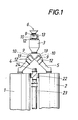
- Fig. 1 eine erfindungsgemäße Beschickungsvorrichtung für einen Zweischachtofen in einer schematischen Vorderansicht,
- Fig. 2 den Schleusenverschluß im Bereich der Einlaßöffnung des Beschickungsbehälters in einem vereinfachten Schnitt in einem größeren Maßstab und
- Fig. 3 einen Schnitt durch die Schleusen verschlüsse für die Anschlußöffnungen der Aufgabeleitungen ebenfalls in einem größeren Maßstab.
- 1 shows a loading device according to the invention for a two-shaft furnace in a schematic front view,
- Fig. 2 shows the lock in the area of the inlet opening the loading container in a simplified section on a larger scale and
- Fig. 3 shows a section through the locks closures for the connection openings of the feed lines also on a larger scale.
Die Beschickungsvorrichtung nach Fig. 1 für die beiden Schächte 1 und 2 eines Zweischachtofens besteht im wesentlichen aus einem Beschickungsbehälter 3, der über zwei Aufgabeleitungen 4 und 5 an die Schächte 1 und 2 angeschlossen ist. Das dosiert in den Beschickungsbehälter 3 eingebrachte Brenngut kann daher abwechselnd den Schächten 1 und 2 zugeführt werden. Zur Beschickung des Behälters 3 dient ein aus Übersichtlichkeitsgründen nicht dargestellter Förderer, der das Brenngut über eine Einlaßöffnung 6 in den Beschickungsbehälter abwirft.1 for the two
Zum Unterschied von bekannten Beschickungsvorrichtungen ist der Beschickungsbehälter 3 als Schleusenkammer ausgebildet, wobei im Bereich der Einlaßöffnung 6 des Beschickungsbehälters und im Bereich der Anschlußöffnungen 7 für die Aufgabeleitungen 4 und 5 Schleusen verschlüsse 8 vorgesehen sind. Diese Schleusenverschlüsse bestehen gemäß dem Ausführungsbeispiel nach den Fig. 2 und 3 aus je einer Verschlußklappe 9, an die ein Schwenkhebel 10 angreift. Dieser Schwenkhebel sitzt auf einer Betätigungswelle 11, die mittels eines Arbeitszylinders 12 über einen Stellhebel 13 verdreht werden kann, wie dies in Fig. 1 angedeutet ist. Die Anordnung ist dabei so getroffen, daß der Schwenkarm 10 mit einem Lagerbolzen 14 in ein Langloch 15 eines Lagerbockes 16 auf der Verschlußklappe 9 eingreift, so daß bei einer Drehverstellung des Schwenkarmes 10 über die Betätigungswelle 11 der Schwenkarm 10 einen Leerhub im Ausmaß des durch das Langloch 15 gegebenen Spieles ausführt, bevor die Verschlußklappe 9 geöffnet werden kann. Dieser Leerhub wird zum Betätigen eines Druckausgleichsventiles 17 ausgenützt, das in der Verschlußklappe 9 vorgesehen ist und über einen Verlängerungshebel 18 des Schwenkarmes 10 geöffnet werden kann.In contrast to known loading devices, the
Wie aus den Fig. 2 und 3 erkennbar ist, ist zu diesem Zweck der Ventilkörper mit dem Verlängerungshebel 18 des Schwenkarmes 10 verbunden.As can be seen from FIGS. 2 and 3, the valve body is connected to the
Soll beispielsweise der Schleusenverschluß 8 für die Anschlußöffnung 7 der Aufgabeleitung 5 geöffnet werden, so wird der Schwenkarm 10 über den zugehörigen Arbeitszylinder 12, den Stellhebel 13 und die Betätigungswelle 11 beaufschlagt, wobei in einem ersten Abschnitt das Druckausgleichsventil 17 geöffnet wird, so daß sich zwischen dem Beschikkungsbehälter 3 und dem Schacht 2 ein Druckausgleich einstellen kann. Danach wird in einem zweiten Abschnitt die Verschlußklappe 9 geöffnet. In Fig. 3 ist die Öffnungsstellung strichpunktiert angedeutet. Nach dem Öffnen der Verschlußklappe kann das Brenngut aus dem Beschickungsbehälter 3 durch die Aufgabeleitung 5 unbehindert in den Schacht 2 gelangen. Daß dabei die Schleusenverschlüsse im Bereich der Einlaßöffnung 6 des Beschickungsbehälters 3 und im Bereich der Anschlußöffnung 7 für die Aufgabeleitung 4 zum Schacht 1 geschlossen sein müssen braucht wohl nicht näher ausgeführt zu werden. Beim Schließen der Verschlußklappe 9 wird der Bewegungsablauf gegensinnig durchlaufen. Nach dem Schließen der Verschlußklappe wird über den Verlängerungshebel 18 das Druckausgleichsventil 17 geschlossen, so daß wieder ein gasdichter Verschluß für den Schacht gewährleistet ist.For example, if the
Um besonders vorteilhafte Dichtungsverhältnisse im Bereich der Schleusenverschlüsse sicherzustellen, weisen die an der Austrittsseite der jeweiligen Öffnung 6 bzw. 7 vorgesehenen Verschlußklappen 9 einen Dichtungskragen 19 auf, mit dem sie einen Randkragen 20 der Einlaßöffnung 6 bzw. der Anschlußöffnung 7 übergreifen. Da der Randkragen 20 gegen die Verschlußklappe 9 hin vorragt und vom Dichtungskragen 19 der Verschlußklappe 9 übergriffen wird, kommen die Dichtungen 21 für die Verschlußklappen 9 mit dem Brenngut nicht in Berührung, was sich vorteilhaft auf die Standzeit auswirkt.In order to ensure particularly advantageous sealing conditions in the area of the lock closures, the
Wie sich aus Fig. 1 schematisch erkennen läßt, können die Schächte 1 und 2 über eine Umschalteinrichtung 22 abwechselnd mit einer Frischluftleitung 23 und einer Abgasleitung 24 verbunden werden, so daß die Brenngase aus dem mit dem Frischluftkanal 23 verbundenen Schacht, beispielsweise dem Schacht 1, über einen nicht dargestellten Überströmkanal in den anderen Schacht 2 gelangen und dort das Brenngut im Gegenstrom vorwärmen können bevor sie aus diesem Schacht 2 über die Abgasleitung 24 entweichen. Nach dem Umstellen der Umschalteinrichtung 22 wird dem vorher im Gegenstrom mit den Verbrennungsgasen aus dem anderen Schacht 1 erwärmten Schacht 2 Brennstoff und Frischluft zugeführt, wobei die Brenngase im Gleichstrom mit dem Brenngut durch den Schacht 2 geleitet werden, um nunmehr das Brenngut im anderen Schacht 1 im Gegenstrom aufzuwärmen. Die Beschickung der beiden Schächte mit Brenngut kann dabei wahlweise während des Gegenstrombetriebes oder während des Gleichstrombetriebes erfolgen.As can be seen schematically from FIG. 1, can the
Claims (3)
Applications Claiming Priority (2)
| Application Number | Priority Date | Filing Date | Title |
|---|---|---|---|
| AT0141185A AT382712B (en) | 1985-05-10 | 1985-05-10 | FEEDING DEVICE FOR A SHAFT OVEN FOR BURNING CARBONATE-CONTAINING MINERAL COMBUSTION |
| AT1411/85 | 1985-05-10 |
Publications (2)
| Publication Number | Publication Date |
|---|---|
| EP0207048A1 true EP0207048A1 (en) | 1986-12-30 |
| EP0207048B1 EP0207048B1 (en) | 1989-01-25 |
Family
ID=3513313
Family Applications (1)
| Application Number | Title | Priority Date | Filing Date |
|---|---|---|---|
| EP86890057A Expired EP0207048B1 (en) | 1985-05-10 | 1986-03-12 | Charging equipment for a shaft furnace for burning mineral materials containing carbonates |
Country Status (11)
| Country | Link |
|---|---|
| US (1) | US4708643A (en) |
| EP (1) | EP0207048B1 (en) |
| KR (1) | KR860009137A (en) |
| CN (1) | CN1006004B (en) |
| AT (1) | AT382712B (en) |
| AU (1) | AU576074B2 (en) |
| DD (1) | DD258054A5 (en) |
| DE (1) | DE3661966D1 (en) |
| DK (1) | DK210286A (en) |
| IN (1) | IN165081B (en) |
| YU (1) | YU44784B (en) |
Cited By (4)
| Publication number | Priority date | Publication date | Assignee | Title |
|---|---|---|---|---|
| DE3834969A1 (en) * | 1988-10-13 | 1990-04-19 | Kortec Ag | FEEDING DEVICE FOR SHAFT OVENS, IN PARTICULAR STOVE OVENS |
| AT405684B (en) * | 1992-12-22 | 1999-10-25 | Wurth Paul Sa | GAS-TIGHT SEPARATOR VALVE FOR SOLIDS |
| DE10333569A1 (en) * | 2003-07-23 | 2005-02-17 | Z & J Technologies Gmbh | Device for distributing bulk material in at least two above the gout of a blast furnace arranged bunker |
| EP1555251A2 (en) | 2004-01-15 | 2005-07-20 | Maerz-Ofenbau AG | Process for burning of particulate mineral solids |
Families Citing this family (5)
| Publication number | Priority date | Publication date | Assignee | Title |
|---|---|---|---|---|
| US5494263A (en) * | 1994-03-07 | 1996-02-27 | Centro De Investigacion Y Asistencia Tecnica Del Edo. De Qro, A.C. | System for solid material charging into vertical reactors by electronic control of the exhaust gases |
| US5595482A (en) * | 1994-10-27 | 1997-01-21 | Parsons; Marshall F. | Airlocking system and method for feeding bulk granular material |
| DE10200960A1 (en) * | 2002-01-12 | 2003-07-24 | Kloeckner Humboldt Wedag | Device for smuggling hot flour-like material |
| ITTO20040919A1 (en) * | 2004-12-29 | 2005-03-29 | Cimprogetti Spa | CYCLIC LOADING SYSTEM TO CALCARE IN REGENERATIVE OVENS EQUIPPED WITH DEVICE INTERNAL PRESSURE EQUALIZER AND USING LOADING PROCEDURE SUCH SYSTEM |
| RU2630992C1 (en) * | 2016-05-31 | 2017-09-15 | Общество С Ограниченной Ответственностью Внедренческое Производственное Предприятие "Известа" | Loading and distribution device of uniflow and counterflow regenerative furnace with round shafts for sintering lumpy carbonate material |
Citations (3)
| Publication number | Priority date | Publication date | Assignee | Title |
|---|---|---|---|---|
| FR1367391A (en) * | 1963-08-30 | 1964-07-17 | Loading device for tank furnaces | |
| DE1902327A1 (en) * | 1969-01-17 | 1970-08-06 | Hischmann Maschinenfabrik Geb | Firing cement raw materials in a shaft - furnace |
| AT377078B (en) * | 1983-05-09 | 1985-02-11 | Maerz Ofenbau | METHOD AND DEVICE FOR LOADING A TWO-SHAFT OVEN |
Family Cites Families (11)
| Publication number | Priority date | Publication date | Assignee | Title |
|---|---|---|---|---|
| CA570461A (en) * | 1959-02-10 | Crucible Steel Company Of America | Furnace charge feeding method and apparatus | |
| US1093936A (en) * | 1914-04-21 | Koppers Company H | Apparatus for discharging vertical retorts. | |
| US1482677A (en) * | 1922-10-04 | 1924-02-05 | Charles J Dunten | Shale retort |
| US3592151A (en) * | 1970-03-09 | 1971-07-13 | Morgan Construction Co | Method and apparatus for refuse incineration |
| AT314408B (en) * | 1972-04-24 | 1974-04-10 | Maerz Ofenbau | Shaft furnace |
| US3952151A (en) * | 1973-08-13 | 1976-04-20 | Trw Inc. | Method and apparatus for stabilized reproduction of remotely-sensed images |
| DE2918005C2 (en) * | 1979-05-04 | 1982-10-14 | Bergwerksverband Gmbh | Apparatus and method for charging a coke oven |
| US4331084A (en) * | 1980-05-09 | 1982-05-25 | The Boeing Company | Fuel feed technique for auger combustor |
| DE3049250C2 (en) * | 1980-12-27 | 1985-10-24 | Kernforschungsanlage Jülich GmbH, 5170 Jülich | Equipment with smoldering drum and shaft furnace |
| AT374275B (en) * | 1982-05-18 | 1984-04-10 | Voest Alpine Ag | DISCHARGE DEVICE FOR A SHAFT OVEN |
| US4451925A (en) * | 1982-09-13 | 1984-05-29 | Hylsa, S.A. | Charging system for electric arc furnaces |
-
1985
- 1985-05-10 AT AT0141185A patent/AT382712B/en not_active IP Right Cessation
-
1986
- 1986-03-12 EP EP86890057A patent/EP0207048B1/en not_active Expired
- 1986-03-12 DE DE8686890057T patent/DE3661966D1/en not_active Expired
- 1986-03-19 IN IN226/CAL/86A patent/IN165081B/en unknown
- 1986-03-25 YU YU461/86A patent/YU44784B/en unknown
- 1986-03-26 AU AU55381/86A patent/AU576074B2/en not_active Ceased
- 1986-03-28 US US06/845,450 patent/US4708643A/en not_active Expired - Lifetime
- 1986-04-18 DD DD86289368A patent/DD258054A5/en unknown
- 1986-04-28 KR KR1019860003272A patent/KR860009137A/en not_active Application Discontinuation
- 1986-04-29 CN CN86102925.9A patent/CN1006004B/en not_active Expired
- 1986-05-07 DK DK210286A patent/DK210286A/en not_active Application Discontinuation
Patent Citations (3)
| Publication number | Priority date | Publication date | Assignee | Title |
|---|---|---|---|---|
| FR1367391A (en) * | 1963-08-30 | 1964-07-17 | Loading device for tank furnaces | |
| DE1902327A1 (en) * | 1969-01-17 | 1970-08-06 | Hischmann Maschinenfabrik Geb | Firing cement raw materials in a shaft - furnace |
| AT377078B (en) * | 1983-05-09 | 1985-02-11 | Maerz Ofenbau | METHOD AND DEVICE FOR LOADING A TWO-SHAFT OVEN |
Cited By (5)
| Publication number | Priority date | Publication date | Assignee | Title |
|---|---|---|---|---|
| DE3834969A1 (en) * | 1988-10-13 | 1990-04-19 | Kortec Ag | FEEDING DEVICE FOR SHAFT OVENS, IN PARTICULAR STOVE OVENS |
| AT405684B (en) * | 1992-12-22 | 1999-10-25 | Wurth Paul Sa | GAS-TIGHT SEPARATOR VALVE FOR SOLIDS |
| DE4340939C2 (en) * | 1992-12-22 | 2003-01-09 | Wurth Paul Sa | Gas-tight partition flap for solids |
| DE10333569A1 (en) * | 2003-07-23 | 2005-02-17 | Z & J Technologies Gmbh | Device for distributing bulk material in at least two above the gout of a blast furnace arranged bunker |
| EP1555251A2 (en) | 2004-01-15 | 2005-07-20 | Maerz-Ofenbau AG | Process for burning of particulate mineral solids |
Also Published As
| Publication number | Publication date |
|---|---|
| US4708643A (en) | 1987-11-24 |
| CN86102925A (en) | 1986-12-17 |
| DD258054A5 (en) | 1988-07-06 |
| KR860009137A (en) | 1986-12-20 |
| YU46186A (en) | 1988-10-31 |
| EP0207048B1 (en) | 1989-01-25 |
| ATA141185A (en) | 1986-08-15 |
| YU44784B (en) | 1991-02-28 |
| CN1006004B (en) | 1989-12-06 |
| IN165081B (en) | 1989-08-12 |
| DE3661966D1 (en) | 1989-03-02 |
| DK210286A (en) | 1986-11-11 |
| AU576074B2 (en) | 1988-08-11 |
| AT382712B (en) | 1987-04-10 |
| DK210286D0 (en) | 1986-05-07 |
| AU5538186A (en) | 1986-11-13 |
Similar Documents
| Publication | Publication Date | Title |
|---|---|---|
| EP0109379B1 (en) | Tyre cladding device for a rotary-drum furnace | |
| EP0207048B1 (en) | Charging equipment for a shaft furnace for burning mineral materials containing carbonates | |
| DE2509400C3 (en) | Fuel injection mechanism | |
| DE2521681C3 (en) | Method and device for operating internal combustion engines | |
| EP0305821A1 (en) | Device for sealing off a tube branch | |
| EP1312861B1 (en) | Apparatus for purifying exhaust air | |
| EP0998542B1 (en) | Device and method for sealing levelling door aperture of a coke oven chamber | |
| DE2004187B2 (en) | DEVICE FOR OPERATING THE LID ON THE RISING PIPE OF A COOKING CHAMBER FURNACE AND THE CLOSING FLAP | |
| DE2855765C2 (en) | Gate valve | |
| DE1295756B (en) | Self-sealing loading device for a shaft furnace or the like. | |
| DE3018361C2 (en) | Arrangement for air regulation in regeneratively heated coking ovens | |
| AT507073B1 (en) | LOCK DEVICE | |
| DE1589532B2 (en) | FEEDING SYSTEM FOR NUCLEAR REACTORS WITH SPHERICAL FUEL ELEMENTS | |
| DE905968C (en) | Chamber furnace battery for coke and gas production with regenerative preheating of the heating gas | |
| EP0046202B1 (en) | System for supplying rinsing and degraphitizing air to the rich gas ducts leading to the single heating walls of coke ovens | |
| DE2328348C3 (en) | Gas-tight feeding device for material into a gas generator | |
| AT384291B (en) | Feeding device for a shaft furnace for burning carbon- containing, mineral combustible material | |
| DE1218950B (en) | Device for discharging powdery or grainy materials from collecting containers | |
| DE2022909C3 (en) | Furnace loading device | |
| DE3016823A1 (en) | ARRANGEMENT FOR RINSING AND CHARGING THE CYLINDERS OF A TWO-STROKE COMBUSTION ENGINE | |
| DE692978C (en) | Suspended gas firing with a crushing roller device on the combustion chamber floor as an injection opening for the compressed air | |
| DE615283C (en) | Air-compressing internal combustion engine, in particular diesel engine | |
| DE20215318U1 (en) | Safety air lock for solid-fuelled furnace has alternately-operated closures | |
| DE3415622C2 (en) | Change slide | |
| DE588819C (en) | Blow molding machine |
Legal Events
| Date | Code | Title | Description |
|---|---|---|---|
| PUAI | Public reference made under article 153(3) epc to a published international application that has entered the european phase |
Free format text: ORIGINAL CODE: 0009012 |
|
| AK | Designated contracting states |
Kind code of ref document: A1 Designated state(s): BE CH DE FR GB IT LI LU NL SE |
|
| 17P | Request for examination filed |
Effective date: 19870211 |
|
| 17Q | First examination report despatched |
Effective date: 19880519 |
|
| RAP1 | Party data changed (applicant data changed or rights of an application transferred) |
Owner name: VOEST-ALPINE INDUSTRIEANLAGENBAU GESELLSCHAFT M.B. |
|
| GRAA | (expected) grant |
Free format text: ORIGINAL CODE: 0009210 |
|
| AK | Designated contracting states |
Kind code of ref document: B1 Designated state(s): BE CH DE FR GB IT LI LU NL SE |
|
| PG25 | Lapsed in a contracting state [announced via postgrant information from national office to epo] |
Ref country code: SE Effective date: 19890125 Ref country code: NL Effective date: 19890125 Ref country code: GB Free format text: LAPSE BECAUSE OF NON-PAYMENT OF DUE FEES Effective date: 19890125 Ref country code: FR Free format text: THE PATENT HAS BEEN ANNULLED BY A DECISION OF A NATIONAL AUTHORITY Effective date: 19890125 Ref country code: BE Effective date: 19890125 |
|
| REF | Corresponds to: |
Ref document number: 3661966 Country of ref document: DE Date of ref document: 19890302 |
|
| ITF | It: translation for a ep patent filed | ||
| EN | Fr: translation not filed | ||
| NLV1 | Nl: lapsed or annulled due to failure to fulfill the requirements of art. 29p and 29m of the patents act | ||
| GBV | Gb: ep patent (uk) treated as always having been void in accordance with gb section 77(7)/1977 [no translation filed] | ||
| PLBE | No opposition filed within time limit |
Free format text: ORIGINAL CODE: 0009261 |
|
| STAA | Information on the status of an ep patent application or granted ep patent |
Free format text: STATUS: NO OPPOSITION FILED WITHIN TIME LIMIT |
|
| 26N | No opposition filed | ||
| ITTA | It: last paid annual fee | ||
| EPTA | Lu: last paid annual fee | ||
| PGFP | Annual fee paid to national office [announced via postgrant information from national office to epo] |
Ref country code: CH Payment date: 20010219 Year of fee payment: 16 |
|
| PGFP | Annual fee paid to national office [announced via postgrant information from national office to epo] |
Ref country code: LU Payment date: 20010223 Year of fee payment: 16 |
|
| PGFP | Annual fee paid to national office [announced via postgrant information from national office to epo] |
Ref country code: DE Payment date: 20010313 Year of fee payment: 16 |
|
| PG25 | Lapsed in a contracting state [announced via postgrant information from national office to epo] |
Ref country code: LU Free format text: LAPSE BECAUSE OF NON-PAYMENT OF DUE FEES Effective date: 20020312 |
|
| PG25 | Lapsed in a contracting state [announced via postgrant information from national office to epo] |
Ref country code: LI Free format text: LAPSE BECAUSE OF NON-PAYMENT OF DUE FEES Effective date: 20020331 Ref country code: CH Free format text: LAPSE BECAUSE OF NON-PAYMENT OF DUE FEES Effective date: 20020331 |
|
| PG25 | Lapsed in a contracting state [announced via postgrant information from national office to epo] |
Ref country code: DE Free format text: LAPSE BECAUSE OF NON-PAYMENT OF DUE FEES Effective date: 20021001 |
|
| REG | Reference to a national code |
Ref country code: CH Ref legal event code: PL |
|
| PG25 | Lapsed in a contracting state [announced via postgrant information from national office to epo] |
Ref country code: IT Free format text: LAPSE BECAUSE OF NON-PAYMENT OF DUE FEES Effective date: 20050312 |