EP0206574B1 - Brosse à dents électrique rotative - Google Patents
Brosse à dents électrique rotative Download PDFInfo
- Publication number
- EP0206574B1 EP0206574B1 EP86304212A EP86304212A EP0206574B1 EP 0206574 B1 EP0206574 B1 EP 0206574B1 EP 86304212 A EP86304212 A EP 86304212A EP 86304212 A EP86304212 A EP 86304212A EP 0206574 B1 EP0206574 B1 EP 0206574B1
- Authority
- EP
- European Patent Office
- Prior art keywords
- brush
- drive shaft
- longitudinal axis
- power
- stem
- Prior art date
- Legal status (The legal status is an assumption and is not a legal conclusion. Google has not performed a legal analysis and makes no representation as to the accuracy of the status listed.)
- Expired - Lifetime
Links
- 230000033001 locomotion Effects 0.000 claims abstract description 43
- 230000005540 biological transmission Effects 0.000 claims abstract description 15
- 230000005291 magnetic effect Effects 0.000 claims description 9
- 230000000087 stabilizing effect Effects 0.000 claims description 6
- 239000003302 ferromagnetic material Substances 0.000 claims description 2
- 230000013011 mating Effects 0.000 claims 2
- 230000001680 brushing effect Effects 0.000 description 12
- 210000001519 tissue Anatomy 0.000 description 9
- 241000894006 Bacteria Species 0.000 description 6
- 239000002253 acid Substances 0.000 description 4
- 239000012530 fluid Substances 0.000 description 4
- 238000000034 method Methods 0.000 description 4
- 230000002441 reversible effect Effects 0.000 description 4
- 102000004190 Enzymes Human genes 0.000 description 3
- 108090000790 Enzymes Proteins 0.000 description 3
- 150000007513 acids Chemical class 0.000 description 3
- 238000004140 cleaning Methods 0.000 description 3
- 208000002925 dental caries Diseases 0.000 description 3
- 239000000463 material Substances 0.000 description 3
- 230000001575 pathological effect Effects 0.000 description 3
- 238000005096 rolling process Methods 0.000 description 3
- 230000006641 stabilisation Effects 0.000 description 3
- 238000011105 stabilization Methods 0.000 description 3
- 238000010408 sweeping Methods 0.000 description 3
- 241000904500 Oxyspora paniculata Species 0.000 description 2
- 208000008312 Tooth Loss Diseases 0.000 description 2
- 210000003298 dental enamel Anatomy 0.000 description 2
- 238000003780 insertion Methods 0.000 description 2
- 230000037431 insertion Effects 0.000 description 2
- 230000003993 interaction Effects 0.000 description 2
- 238000004519 manufacturing process Methods 0.000 description 2
- 208000028169 periodontal disease Diseases 0.000 description 2
- 229920003023 plastic Polymers 0.000 description 2
- 239000004033 plastic Substances 0.000 description 2
- 210000004872 soft tissue Anatomy 0.000 description 2
- 235000000346 sugar Nutrition 0.000 description 2
- 231100000331 toxic Toxicity 0.000 description 2
- 230000002588 toxic effect Effects 0.000 description 2
- 208000003433 Gingival Pocket Diseases 0.000 description 1
- 208000025157 Oral disease Diseases 0.000 description 1
- 208000037273 Pathologic Processes Diseases 0.000 description 1
- 230000009471 action Effects 0.000 description 1
- 210000003484 anatomy Anatomy 0.000 description 1
- 230000003139 buffering effect Effects 0.000 description 1
- 230000015556 catabolic process Effects 0.000 description 1
- 230000001055 chewing effect Effects 0.000 description 1
- 230000001684 chronic effect Effects 0.000 description 1
- 239000012141 concentrate Substances 0.000 description 1
- 210000002808 connective tissue Anatomy 0.000 description 1
- 238000010276 construction Methods 0.000 description 1
- 238000007796 conventional method Methods 0.000 description 1
- 238000010790 dilution Methods 0.000 description 1
- 239000012895 dilution Substances 0.000 description 1
- 201000005562 gingival recession Diseases 0.000 description 1
- 230000005389 magnetism Effects 0.000 description 1
- 230000007246 mechanism Effects 0.000 description 1
- 229910052751 metal Inorganic materials 0.000 description 1
- 239000002184 metal Substances 0.000 description 1
- 150000002739 metals Chemical class 0.000 description 1
- 208000030194 mouth disease Diseases 0.000 description 1
- 230000009054 pathological process Effects 0.000 description 1
- 230000002028 premature Effects 0.000 description 1
- 230000008569 process Effects 0.000 description 1
- 230000001681 protective effect Effects 0.000 description 1
- 230000003252 repetitive effect Effects 0.000 description 1
- 239000012858 resilient material Substances 0.000 description 1
- 230000004044 response Effects 0.000 description 1
- 230000000717 retained effect Effects 0.000 description 1
- 210000003296 saliva Anatomy 0.000 description 1
- 210000004927 skin cell Anatomy 0.000 description 1
- IHQKEDIOMGYHEB-UHFFFAOYSA-M sodium dimethylarsinate Chemical class [Na+].C[As](C)([O-])=O IHQKEDIOMGYHEB-UHFFFAOYSA-M 0.000 description 1
- 238000009987 spinning Methods 0.000 description 1
- 150000008163 sugars Chemical class 0.000 description 1
- 239000002699 waste material Substances 0.000 description 1
Images
Classifications
-
- A—HUMAN NECESSITIES
- A61—MEDICAL OR VETERINARY SCIENCE; HYGIENE
- A61C—DENTISTRY; APPARATUS OR METHODS FOR ORAL OR DENTAL HYGIENE
- A61C17/00—Devices for cleaning, polishing, rinsing or drying teeth, teeth cavities or prostheses; Saliva removers; Dental appliances for receiving spittle
- A61C17/16—Power-driven cleaning or polishing devices
- A61C17/22—Power-driven cleaning or polishing devices with brushes, cushions, cups, or the like
- A61C17/32—Power-driven cleaning or polishing devices with brushes, cushions, cups, or the like reciprocating or oscillating
- A61C17/34—Power-driven cleaning or polishing devices with brushes, cushions, cups, or the like reciprocating or oscillating driven by electric motor
- A61C17/3409—Power-driven cleaning or polishing devices with brushes, cushions, cups, or the like reciprocating or oscillating driven by electric motor characterized by the movement of the brush body
- A61C17/3418—Rotation around the axis of the toothbrush handle
-
- A—HUMAN NECESSITIES
- A61—MEDICAL OR VETERINARY SCIENCE; HYGIENE
- A61C—DENTISTRY; APPARATUS OR METHODS FOR ORAL OR DENTAL HYGIENE
- A61C17/00—Devices for cleaning, polishing, rinsing or drying teeth, teeth cavities or prostheses; Saliva removers; Dental appliances for receiving spittle
- A61C17/16—Power-driven cleaning or polishing devices
- A61C17/22—Power-driven cleaning or polishing devices with brushes, cushions, cups, or the like
- A61C17/24—Power-driven cleaning or polishing devices with brushes, cushions, cups, or the like rotating continuously
- A61C17/26—Power-driven cleaning or polishing devices with brushes, cushions, cups, or the like rotating continuously driven by electric motor
-
- A—HUMAN NECESSITIES
- A61—MEDICAL OR VETERINARY SCIENCE; HYGIENE
- A61C—DENTISTRY; APPARATUS OR METHODS FOR ORAL OR DENTAL HYGIENE
- A61C17/00—Devices for cleaning, polishing, rinsing or drying teeth, teeth cavities or prostheses; Saliva removers; Dental appliances for receiving spittle
- A61C17/16—Power-driven cleaning or polishing devices
- A61C17/22—Power-driven cleaning or polishing devices with brushes, cushions, cups, or the like
- A61C17/32—Power-driven cleaning or polishing devices with brushes, cushions, cups, or the like reciprocating or oscillating
- A61C17/34—Power-driven cleaning or polishing devices with brushes, cushions, cups, or the like reciprocating or oscillating driven by electric motor
- A61C17/349—Power-driven cleaning or polishing devices with brushes, cushions, cups, or the like reciprocating or oscillating driven by electric motor with multiple brush bodies
-
- A—HUMAN NECESSITIES
- A61—MEDICAL OR VETERINARY SCIENCE; HYGIENE
- A61C—DENTISTRY; APPARATUS OR METHODS FOR ORAL OR DENTAL HYGIENE
- A61C17/00—Devices for cleaning, polishing, rinsing or drying teeth, teeth cavities or prostheses; Saliva removers; Dental appliances for receiving spittle
- A61C17/16—Power-driven cleaning or polishing devices
- A61C17/22—Power-driven cleaning or polishing devices with brushes, cushions, cups, or the like
- A61C17/32—Power-driven cleaning or polishing devices with brushes, cushions, cups, or the like reciprocating or oscillating
- A61C17/34—Power-driven cleaning or polishing devices with brushes, cushions, cups, or the like reciprocating or oscillating driven by electric motor
- A61C17/36—Power-driven cleaning or polishing devices with brushes, cushions, cups, or the like reciprocating or oscillating driven by electric motor with rinsing means
-
- A—HUMAN NECESSITIES
- A61—MEDICAL OR VETERINARY SCIENCE; HYGIENE
- A61C—DENTISTRY; APPARATUS OR METHODS FOR ORAL OR DENTAL HYGIENE
- A61C17/00—Devices for cleaning, polishing, rinsing or drying teeth, teeth cavities or prostheses; Saliva removers; Dental appliances for receiving spittle
- A61C17/16—Power-driven cleaning or polishing devices
- A61C17/22—Power-driven cleaning or polishing devices with brushes, cushions, cups, or the like
- A61C17/32—Power-driven cleaning or polishing devices with brushes, cushions, cups, or the like reciprocating or oscillating
- A61C17/34—Power-driven cleaning or polishing devices with brushes, cushions, cups, or the like reciprocating or oscillating driven by electric motor
- A61C17/3409—Power-driven cleaning or polishing devices with brushes, cushions, cups, or the like reciprocating or oscillating driven by electric motor characterized by the movement of the brush body
- A61C17/3445—Translation along the axis of the toothbrush handle
-
- A—HUMAN NECESSITIES
- A61—MEDICAL OR VETERINARY SCIENCE; HYGIENE
- A61C—DENTISTRY; APPARATUS OR METHODS FOR ORAL OR DENTAL HYGIENE
- A61C2204/00—Features not otherwise provided for
- A61C2204/002—Features not otherwise provided for using batteries
-
- Y—GENERAL TAGGING OF NEW TECHNOLOGICAL DEVELOPMENTS; GENERAL TAGGING OF CROSS-SECTIONAL TECHNOLOGIES SPANNING OVER SEVERAL SECTIONS OF THE IPC; TECHNICAL SUBJECTS COVERED BY FORMER USPC CROSS-REFERENCE ART COLLECTIONS [XRACs] AND DIGESTS
- Y10—TECHNICAL SUBJECTS COVERED BY FORMER USPC
- Y10T—TECHNICAL SUBJECTS COVERED BY FORMER US CLASSIFICATION
- Y10T74/00—Machine element or mechanism
- Y10T74/18—Mechanical movements
- Y10T74/18024—Rotary to reciprocating and rotary
- Y10T74/18032—Rotary to reciprocating or rotary
Definitions
- the present invention relates to electric toothbrushes in general and, in particular, to electric toothbrushes providing a rotary brushing action.
- Plaque is a sticky, translucent mass composed mainly of bacteria that are able to form long filamentous strands allowing the bacteria to adhere to smooth surfaces of the teeth and gums. These bacteria feed on dissolved sugars, sloughed skin cells, and tissue fluids. They produce waste products, acids and enzymes that are toxic to both tooth enamel and gingival tissues, including, the gums, those gingival tissues immediately surrounding the teeth. If left undisturbed for 24-36 hours, the individual plaque bacteria develop into mature colonies that have the capacity to concentrate the acids, isolate them from dilution by the buffering action of saliva, and hold the acids against the tooth surface.
- plaque build-up is chronic and sugar consumption is repetitive, the incessant acid insults first demineralize and then cavitate the enamel surface. This cavitation is the process we call dental caries or tooth decay.
- the toxic enzymes produced by plaque bacteria have the capacity to breakdown connective tissue holding gingival tissue together. If the plaque enzymes contact the gingival tissue of the sulcus area, the V-shaped crevice where the tooth and gum come together, the attachment of the gum to the tooth can loosen and a pocketforms. The depth of this gingival pocket is the pathologic barometer of the severity of periodontal disease.
- Toothbrushing is the most successful widely practiced method of removing plaque from the mouth.
- the complex anatomy of the teeth and gums requires two distinct brushing motions to remove plaque effectively.
- very few people ever master these two brushing motions which are relatively complex and require a high degree of dexterity.
- the brushing motions also require more time than most people are willing to spend brushing their teeth.
- the first brushing motion is a rolling or rotary brush motion beginning at the gum at the base of the tooth and continuing across the tooth to its biting surface.
- This rotary or rolling motion is known to be the most effective method of cleaning the tooth surfaces facing the spaces between the teeth known as the interdental spaces.
- the second brushing motion needed for thorough plaque removal is a series of rapid but very short vibratory strokes. To correctly execute the vibratory motion, the brush is placed along the gum line with some of the bristles gently inserted into the sulcus. The brush handle then is moved back and forth about one-eighth of an inch, with the bristle tips held stationary within the sulcus. This important vibratory motion removes plaque from the otherwise hard to reach sulcus.
- the ideal electric toothbrush would safely simulate both rotary and vibratory brushing motions.
- Electric brushes have been designed using a rotary principle with spinning, cylinder-shaped brushes.
- Rotary toothbrushes having but one brush generally are provided with a reversible motor.
- the reversible motor is important because, in order to avoid sweeping mouth fluids into the sulcus and pushing gingival tissue away from the tooth, the brush has to spin in a downward direction against upper teeth and in an upward direction against lower teeth.
- Examples of such toothbrushes include Kurachi, U.S. Patent No. 3,739,416; Grossman, U.S. Patent No. 3,551,932; Koblanski, U.S. Patent No. 3,829,922; Quint, U.S. Patent No.
- Patent No. 4,313,237; and Caliendo, U.S. Patent No. 3,925,841 show more complicated devices utilizing three rotary brushes, two adapted to sweep upwardly, one on either side of a row of teeth, and a third to sweep across the chewing surface of the teeth.
- These three brush designs solve the directional problem in that the brushes always rotate in the correct direction relative to the sulcus.
- the three brush arrangement tends to be fairly large and awkward to use for that reason.
- Taylor, U.S. Patent No. 3,512,201; and Taylor, U.S. Patent No. 3,512,202, show toothbrushes that appear to be unique in providing for both a rotary brushing action and an independent, reciprocating motion of generally cylindrical brushes moving in a direction parallel to their longitudinal axes.
- the Tavlor brushes utilize two motors, one to rotate the brushes and a second to reciprocate them axially.
- a rotary electric toothbrush includes a power handle having a foot and a motor, the motor having a rotatable power shaft. Means are included for supplying electrical power to the motor.
- a longitudinally extended brush stem is attached to the power handle at a point remote from the foot thereof and extends therefrom to terminate at a stem head.
- a brush cartridge is attached to the stem head and extends therefrom to terminate at a toothbrush head.
- “headward” indicates the direction toward the toothbrush head and "footward” indicates the direction toward the foot.
- the brush cartridge includes at least one generally cylindrical brush, the longitudinal axis of which is oriented approximately headward-to-footward.
- a drive shaft extends from the power handle to the brush, the headward end of the drive shaft including means for engaging the brush and transmitting to it the motion of the drive shaft.
- Transmission means are provided for transmitting the motion of the power shaft to selectively cause the drive shaft alternatively to rotate about its longitudinal axis and to move parallel thereto in a reciprocating manner.
- a user of the electric toothbrush may direct power from a single motor selectively to cause the brush to rotate about its longitudinal axis or to move in a reciprocating manner parallel thereto.
- a primary object of the invention is to provide an electric toothbrush having brushes capable of selectively moving either in a rotary or a reciprocating manner.
- a second object of the invention is to provide for such a toothbrush in which a single motor can be used to drive the brushes in either a rotary or a reciprocating manner.
- Another object of the invention is to provide such a toothbrush in which the brushes are joined to the motor by drive shafts capable of transmitting power either in a rotary or reciprocating manner.
- a further object of the invention is to provide such a toothbrush in which the motor and the oral soft tissues are protected from torque overloads.
- a further object of the invention is to provide such a toothbrush having easily replacable brushes.
- Yet another object of the invention is to provide for removable brush stems so that each member of a household may use a different brush stem.
- a further object of the invention is to provide for two brush head sizes, one for adults and another for children, both of which may be used with a single power handle.
- a further object of the invention is to insure that the rotating brushes are always moving in the correct direction relative to gum tissue.
- Yet another object of the invention is to provide a brush whose bristle tips can easily reach and clean all teeth in the mouth.
- a further object of the invention is to provide a brush that is portable.
- Yet another object of the invention is to provide such a toothbrush that is economical to manufacture and durable of design.
- a further object of the invention is to provide such a toothbrush in which the speed of operation of the brush is adjustable for operation in each of the two manners of movement referred to.
- a further object of the invention is to provide such a toothbrush in which the relative speed of operation in the rotary and reciprocating modes can be preset, independent of adjustments to motor speed.
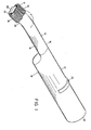
- Fig. 1 shows a first embodiment of an electric toothbrush, generally indicated at 10, constructed in accord with the present invention.
- the electric toothbrush 10 includes a power handle 12 and a longitudinally extended brush stem 14.
- the brush stem 14 is removable from the power handle 12 by means to be discussed below, so that more than one brush stem may be used interchangably with a single power handle.
- the brush stem 14 has a stem base 16 adjacent to the power handle 12, a stem throat 18, and a stem head 20 remote from the stem base.
- a brush cartridge 21 is attached to the stem head 20.
- the brush cartridge 21 may be so attached permanently, constituting a unitary continuation of the brush stem 14, as is shown in Fig. 3.
- the brush cartridge also may be removably attached to the brush stem by means for attachment discussed below.
- the power handle 12 extends from its point of attachment to the brush stem 14 to terminate at a foot 22.
- the brush cartridge 21 extends from the stem head 20 to terminate at a toothbrush head 23, which is that portion of the toothbrush 10 most remote from the foot 22.
- the parts of the electric toothbrush 10 may be referred to as having "headward” or “footward” ends, portions or movement.
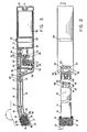
- the electric toothbrush 10 includes an electric motor indicated schematically at 24 in Fig. 3.
- the motor 24 is located in the power handle 12 and has a rotating power shaft 26 extending headwardly from the motor.
- the motor 24 may be a nonreversing motor and preferably includes means to selectively vary the speed of the motor, such as the rheostat shown at 28 having an externally mounted, finger operable control 29.
- the electric toothbrush 10 further includes means for supplying electrical power to the motor 24.
- a rechargable battery is located in the power handle 12, as is indicated schematically at 30 in Fig. 3. If so, a plug connection such as that shown at 31 in Fig. 3 is provided for connecting the battery 30 to a suitable charging device.
- alternative means for supplying electrical power are clearly possible, such as a power cord extending from the power handle 12 to an external source of electrical power.
- At least one and preferably two, rigid drive shafts 32 extend from the vicinity of the power shaft 26 in the power handle 12 toward the toothbrush head 23.
- the drive shafts 32 are supported by bearings such as the sleeve bearings shown at 34 that include means to allow the drive shafts both to rotate and to move in a reciprocating manner parallel to the longitudinal axes of the drive shafts.
- the drive shafts 32 preferably are cylindrical.
- Transmission means are provided for transmitting the motion of the power shaft 26 to the drive shafts 32 to selectively cause the drive shafts either to rotate or to move in a reciprocating manner, as described.
- a variety of such transmission means are possible.
- a magnetic clutch plate 36 is allowed to slide longitudinally on the power shaft 26 within a limited range.
- the magnetic clutch plate 36 is forced to rotate with the power shaft 26 by means of a key 38.
- the key 38 extends parallel to the longitudinal axis of and is rigidly mounted on the power shaft 26.
- the magnetic clutch plate 36 includes a longitudinally extending slot 40 having a size sufficient to allow the clutch plate to move freely over the key 38 but only in a direction parallel to the longitudinal axis of the power shaft 26.
- a mode selector switch 42 is adapted to move the clutch plate 36 longitudinally along the power shaft 26 to selected locations thereon.
- First and second freely turning gears 44, 46 are mounted on the power shaft 26 in freely turning relation thereto, the first freely turning gear 44 being located headwardly of the magnetic clutch plate 36 and the second freely turning gear 46 being located footwardly therefrom.
- Each of the freely turning gears 44, 46 are restrained from substantial movement longitudinally on the power shaft 26.
- the freely turning gears 44, 46 are made of ferromagnetic material. Consequently, when the mode selector switch 42 is utilized to move the magnetic clutch plate 36 into contact with one of the freely turning gears 44, 46, the clutch plate becomes magnetically engaged therewith, tending to turn that freely turning gear but capable of slipping thereon if the torque necessary to turn the freely turning gear exceeds a selected amount.
- the transmission includes protective means for protecting the motor 24 and oral soft tissues in the event the freely turning gears 44, 46 become jammed or stalled.
- the magnetic clutch plate 36 is preferred, a comparable and equivalent clutch plate arrangement may be designed using springs instead of magnetism to force the clutch plate against the freely turning gears 44, 46.
- the first freely turning gear 44 is engaged with a first driven gear 48.
- the first driven gear 48 turns a secondary power shaft 50 on which is mounted a headwardly facing swash plate 52.
- the longitudinal axis of the swash plate 52 is oriented generally parallel to the longitudinal axes of the drive shafts 32.
- the swash plate 52 has a generally headwardly facing driving surface 54 canted to the longitudinal axis of the swash plate.
- a crank pivot pin 56 extends generally headwardly at right angles to the driving surface 54.
- a longitudinally extended crank rod 58 is engaged over the crank pivot pin 56 in freely turning relation thereto.
- crank rod 58 remote from the crank pivot pin 56 will reciprocate in a headward-to-footward direction when the swash plate 52 is rotated and the crank rod is restrained from rotating with it.
- a stroke plate 60 is attached to the crank: rod 58 at a point remote from the crank pivot pin 56.
- the crank rod 58 is attached to the stroke plate 60 both in freely pivoting relation, preferably by means of a spherical bearing, and with freedom to move relative to the stroke plate in a direction parallel to the longitudinal axis of the crank rod 58, preferably by means of a sleeve bearing or the like.
- the spherical and sleeve bearings may be parts of a single complex bearing, such as the stroke plate bearing indicated at 61 in Fig. 3.
- the stroke plate 60 is driven alternately headwardly and footwardly in a reciprocating manner.
- the stroke plate 60 is attached to each of the drive shafts 32 by bearings that allow the drive shafts to rotate freely with respect to the stroke plate about their longitudinal axes but that prevent movement of the drive shafts relative to the stroke plate in a direction parallel to their longitudinal axes.
- the drive shafts 32 each have a section of reduced diameter, shown in phantom in Fig. 2 at 62.
- the stroke plate 60 then may be attached to the drive shafts 32 by drive shaft sleeve bearings 63 (shown in phantom in Fig.
- the second freely turning gear 46 turns a second driven gear 64.
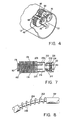
- the second driven gear 64 is attached to a first one of the drive shafts 32, which shall be referred to as the "primary drive shaft,” shown in Fig. 4 at 66.
- the remaining drive shaft 32 shall be referred to as the "secondary drive shaft,” indicated in Fig. 4 at 68.
- a driving coordinating gear 70 is attached to the primary drive shaft 66 and turns with it.
- a driven coordinating gear 72 is attached to the secondary drive shaft 68 and is driven by the driving coordinating gear 70.
- the primary and secondary drive shafts 66, 68 rotate about their longitudinal axes in opposite directions.
- the brush cartridge 21 includes at least one and preferably two, generally cylindrical brushes 74.
- the cylindrical brushes 74 are located side by side and preferably intermesh slightly.
- the brushes 74 are attached by their footward ends to the headward-most ends of the drive shafts 32 and are driven by them.
- the headward end of each of the brushes 74 is mounted in an end bearing 76 that includes means to allow the brushes to rotate freely about their longitudinal axes and also to move axially in a reciprocating manner.
- the brush cartridge 21 includes a shield member 78 extending from the footward-most end of the brush cartridge first to one side and then headwardly beyond the brushes 74.
- An end cap 80 extends from the shield member 78 across a selected portion of the headward- most end of the brushes 74.
- the end cap 80 is hingedly attached to the shield member 78, allowing portions of the end cap to move headwardly and footwardly.
- the end cap 80 and shield member 78 may be unitarily molded, linked by a thinned, molded web capable of flexing in a hinge- like manner, such structures being known in the art as "living hinges.”
- the end cap 80 is biased toward the footward direction and holds the end bearings 76 on footwardly facing surfaces thereof.
- the end bearings 76 are biased against the headward ends of the brushes 74 but also can be resiliently forced headwardly by the brushes when the brushes are in their reciprocating mode.
- the structure just described is that preferred as a brush support means for supporting the brushes 74 so as to accommodate both axial and rotary brush movement.
- the shield member 78 could be telescoping in a headward-to-footward direction, biased toward a shorter length.
- the end cap 80 could be rigidly joined to the shield member 78 and still be footwardly biased.
- the brushes 74 could be made stiff enough not to require support at both the headward and footward end. In such an arrangement, the attachment of the brushes 74 to the drive shafts 32 would have to be sufficiently secure to draw the brush footwardly when in the reciprocating mode without the aid of a footwardly biased end cap 80.
- brushes 74 so attached to the drive shafts 32 could receive lateral support from appropriate bearings in an end cap 80 without the need of a footwardly biased end cap.
- the cylindrical brushes of a rotary toothbrush so oriented that that side of the cylindrical brush or brushes intended to contact the teeth of a user is tipped slightly endwardly, away from the remaining parts of the electric toothbrush.
- the longitudinal axes of the cylindrical brushes 74 be oriented at an angle "A" in excess of 180° to the longitudinal axis of the brush stem 14, as is shown in Figs. 1 and 3.
- the angle "A" be less than 180 ° (not shown) so that the side of the brushes 74 intended to contact the user's teeth is tipped footwardly.
- each drive shaft 32 includes means for transmitting both torque and axially directed force.
- a drive shaft 32 including means for transmitting both torque and axially directed force.
- flexible wire shafts contained within sleeves or woven cable shafts would be suitable.
- the drive shafts 32 each are equipped with two universal joints, each universal joint inserted into the drive shaft and separated from each other by a substantially rigid portion of the drive shaft, which arrangement shall be referred to herein as a double universal joint, as shown at 82 in Fig. 3.
- the double universal joint 82 is located approximately at the stem head 20.
- the sleeve bearings 34 include bearings located immediately headwardly and footwardly of the double universal joints 82, as is indicated in Fig. 3.
- the double universal joints 82 are capable of efficiently transferring both rotary and axial motion, allowing the brushes 74 to rotate or to reciprocate axially in response to the transmission means for transmitting the motion of the power shaft 26 to the drive shafts 32, as disclosed above.
- the brush stem 14 preferably is entirely removable from the power handle 12 being joined thereto by stem attachment means for removably attaching the brush stem to the power handle.
- the stem attachment means may have any of various possible structures, one of which is shown in the first embodiment. Alternative stem attachment means will be discussed below, but in general such attachment means includes means for stabilizing the joint and means for releasably interlocking separable portions of the drive shafts 32.
- the brush stem 14 has an engagement prong 84.
- the engagement prong 84 extends footwardly from the footward-most end of the brush stem 14 in a direction generally parallel to the drive shafts 32.
- An engagement well 86 is formed in the headward-most end of the power handle 12 and is adapted to receive the engagement prong 84.
- the footward end 85 of the engagement prong 84 is oversized with respect to the engagement well 86, slotted, and made of a resilient material so that the footward end of the engagement prong is compressed upon insertion into the engagement well.
- the engagement well 86 may include an enlarged portion 88 in which the oversized end 85 of the engagement prong 84 may be received and may expand to hold the engagement prong within the engagement well.
- the engagement prong 84 and associated structures are an example of means for joint stabilization.
- the drive shafts 32 are separable into brush stem portions 89 and power handle portions 91.
- the brush stem and power handle portions 89, 91 of the drive shafts 32 are equipped with press-fit engagement devices such as the split resilient collars shown at 90 in Fig. 2.
- the split collars 90 are rigidly attached to one portion of the drive shaft 32 and are adapted to slip over the end of the other portion of the drive shaft in resiliently clamping relation.
- the split collars 90 and associated structures described are an example of means for releasably interlocking separable portions of the drive shafts 32.
- each brush 74 may include a central spindle 92 terminating in a footwardly extending, flattened spade end 94.
- the headward- most ends of the drive shafts 32 each may be equipped with a headwardly opening brush slot 96 capable of receiving and holding the spade end 94 of a brush 74.
- the end bearings 76 may include means to releasably hold the headward ends of the brushes 74, so that a user may pull the end cap 80 headwardly until the headward ends of the brushes 74 may be slipped out of the end bearings 76 and the spade ends 94 of the central spindles 92 withdrawn from the brush slots 96. This action may be reversed to install a brush 74.
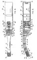
- a second embodiment of an electric toothbrush constructed in accord with the invention is shown at 110 in Figs. 5 and 6.
- the second embodiment 110 has many parts that are essentially the same as the corresponding parts of the first embodiment shown at 10, as described above. Corresponding parts of the second embodiment will be given corresponding reference numbers except that those reference numbers shall be higher than the reference numbers of the first embodiment by 100.
- the second embodiment 110 has a power handle 112 corresponding to the power handle 12 of the first embodiment 10, and so forth. The function and structure of these corresponding parts will not be separately discussed. Parts of the second embodiment discussed and not having a corresponding part in the first embodiment all will have reference numbers at least as great as 198.
- the transmission means of the second embodiment 110 for transmitting the motion of the power shaft 126 to the drive shafts 132 to selectively cause the drive shafts to rotate or to move in a reciprocating manner is an illustration of one of several alternative embodiments of suitable transmission means.
- the transmission means of the second embodiment cooperates with a motor 124 having a power shaft 126. Unlike the otherwise corresponding motor 24 of the first embodiment, the motor 124 of the second embodiment is electrically reversible.
- the transmission means of the second embodiment includes first and second, conventional, one way clutch-driven gears 198, 200.
- the first one way clutch-driven gear 198 includes means for engaging the power shaft 126 exclusively when the power shaft is turning in a first direction.
- the second one way clutch-driven gear 200 includes means for engaging the power shaft 126 exclusively when the power shaft is turning in the opposite direction.
- the first one way clutch-driven gear 198 is engaged with a first driven gear 148.
- the first driven gear 148 is mounted on a secondary power shaft 150 having a swash plate 152 associated with a crank rod 158, stroke plate 160, and so forth, in the same manner as the corresponding and associated parts are related in the first embodiment 10 disclosed above.
- the first one way clutch-driven gear 198 engages the power shaft 126 and is turned thereby, causing the drive shafts 132 to move in a reciprocating manner.
- the second one way clutch-driven gear 200 is engaged with a second driven gear 164 corresponding to the second driven gear 64 of the first embodiment.
- the second driven gear 164 is mounted on a primary drive shaft 166.
- a secondary drive shaft 168 is caused to rotate in a direction opposite to the rotational direction of the primary drive shaft 166 by the interaction of driven and driving coordinating gears 170, 172, having the same structure and mode of interaction as the corresponding parts of the first embodiment.
- the second one way clutch-driven gear 200 engages the power shaft 126, causing the drive shafts 132 to rotate about their longitudinal axes.
- the second embodiment includes reversing means for reversing the direction of rotation of the motor 124.
- the reversing means effectively allows a user to select between a rotary and a reciprocating brush motion.
- the reversing means may include a separate reversing switch or, as is preferred, may be incorporated in the rheostat 128 by which the speed of the motor 124 is also controlled. It will be apparent that, with both the first and second embodiments, a user may select between rotary and reciprocating modes of operation and separately may select the speed of operation in either mode.
- gear ratios between the driven gears 48, 64, 148, 164 and those gears driving them may be adjusted so as to provide a desirable relationship between the speed of rotation of the brushes 74, 174 and the rate at which they reciprocate at any given motor speed.
- a conventionally designed, spring-loaded, slipping clutch may be inserted in the transmission means at any convenient location.
- Each of the particular transmission means described utilized a swash plate 52, 152 and an attached crank rod 58, 158 and stroke plate 60, 160 to transform the circular motion of the secondary power shaft 150 into a reciprocating motion.
- many mechanical means for translating rotary motion to reciprocal motion are known to those skilled in the art.
- cams of various sort may be rotated by a shaft and drive a cam follower in a manner that is either directly reciprocating or that may be transformed into a reciprocating motion by a suitable linkage.
- the drive shafts 132 of both embodiments 10 and 110 are adapted to be unitarily molded from a plastic or other flexible, moldable material.
- the drive shafts 132 each include means for transmitting both rotary and axially directed motion that are an alternative means to the double universal joint 82 employed in the drive shafts 32 shown as part of the first embodiment 10.
- Each drive shaft 132 of the second embodiment includes a flexible portion 202 of the drive shaft, best seen in Fig. 8.
- the flexible portion 202 has a central shaft 203 and a helicoid member 204 having a diameter greater than that of the central shaft.
- the helicoid member 204 extends for the full length of the flexible portion 202.
- the flexible portion 202 exhibits a reduced resistance to lateral flexing when compared to the remaining portions of the drive shaft 132.
- the central shaft 203 effectively transmits force directed axially thereto, and the helicoid member 204 effectively transmits torque.
- the brush cartridge may be formed unitarily with the stem, as it is shown at 21 and 14 in the first embodiment 10.
- the brush cartridge also may be separable from the stem, as is shown in the second embodiment 110 at 121 and 114 with a joint thus established therebetween.
- cartridge attachment means are provided for releasably attaching the cartridge 121 to the stem head 120.
- the cartridge attachment means is generally analogous to the stem attachment means discussed above with relation to the first embodiment 10. Thus, it includes means for stabilizing the joint and means for releasably interlocking separable portions of the drive shafts.
- the cartridge attachment means may be physically analogous to the particular stem attachment means disclosed above with respect to the first embodiment 10, with an engagement prong, engagement well, and resilient split collars or comparable means for releasably interlocking separable portions of the drive shafts.
- the preferred embodiment of the cartridge attachment means is that shown as part of the second embodiment 110 of the electric toothbrush, as seen in Figs. 5 and 7.
- the means for joint stabilization includes a joint sleeve 206 extending footwardly from the footwardmost end of the brush cartridge 121. Interior surfaces of the joint sleeve 206 define a footwardly opening joint socket 208.
- the joint socket 208 is non-round in lateral cross-sectional shape and preferably oval, trapezoidal, or the like.
- a male socket member 210 extends headwardly from the stem head 120.
- the male socket member 210 has a size and cross-sectional shape so selected that the male socket member may slide snugly in and out of the joint socket 208. Because of the non-round cross-sectional shape of the joint socket 208, the male socket member 210 is restrained from axial rotation within the joint socket.
- An entirely equivalent structure is obtainable by forming a joint socket at the headward end of the brush stem and a male socket member at the footward end of the brush cartridge.
- detent means are provided for releasably retaining the male socket member 210 within the joint socket 208.
- the male socket member 210 has a ridge 212
- the joint socket 208 includes a groove 214, the ridge and groove being so positioned and having a size such that, when the male socket member is inserted into the joint socket, the ridge resiliently snaps into the groove to be releasably retained therein.
- the brush cartridge 121 of the second embodiment 110 has cylindrical brushes 174 generally comparable to the cylindrical brushes 74 of the first embodiment 10.
- the cylindrical brushes 174 each have a brush central spindle 192 that is continuous with a portion 220 of the associated drive shaft 132 separable from the brush stem portion 189 of the drive shaft.
- the footward end of each central spindle 192 extends into the joint socket 208, terminating in a round end 222.
- the brush stem portion 189 of each drive shaft 132 terminates at the stem head 120 and has a resilient split collar 224 opening headwardly.
- the round ends 222 may be engaged in the split collars 224 to be removably engaged thereby.
- the round ends 222 and split collars 224 are an example of means for releasably interlocking the separable brush cartridge portions 220 and the brush stem portions 189 of the drive shafts 132.
- the brushes 174 of the rotary electric toothbrush 110 may quickly and easily be changed. Furthermore, the brushes 174 may be changed by a person of only modest manual dexterity. Individual brushes need not be handled or placed in an exacting relationship to other parts. Instead, the entire brush cartridge 121 may simply be unplugged and replaced with a new one. Furthermore, by this arrangement, brush cartridges 121 of different sizes may be employed with a single brush stem 114, making it possible for a user to select among brushes of differing stiffness or abrasive characteristics or to select larger or smaller sizes of the brush cartridge. Thus, brush cartridges 121 may be furnished in small, pediatric sizes as well as in larger, adult sizes.
- the end cap 180 of the brush cartridge 121 need not be able to endure as wide a range of motion as was described as necessary for the corresponding structure of the first embodiment of an electric toothbrush identified above at 10.
- the end cap 180 of the second embodiment 110 of the electric toothbrush is capable of resiliently flexing in hinged relation to the shield member 178 as the brushes 174 are moved in a reciprocating manner.
- the brushes 174 are mounted within the brush cartridge 121 at the time of manufacture, it is unnecessary subsequently to replace them. Instead, the entire brush cartridge 121 may be discarded and replaced with a new one.
- the stem attachment means described with respect to the first embodiment 10 of the electric toothbrush of the invention and the cartridge attachment means, a particular example of which has just been described as part of the second embodiment 110, are deemed to be structural equivalents.
- the two particular structures described could be exchanged for each other and for other equivalent attachment means that include means for joint stabilization and means for releasably interlocking separable portions of the drive shafts.
- the stem attachment means illustrated in the figures showing the second embodiment 110 combines features of each of the particular structures just referred to.
- an engagement prong 184 extends footwardly from the stem base 116 and terminates in a resiliently compressible oversized end 185.
- the power handle 112 has an engagement well 186 opening headwardly and having an enlarged portion 188, all adapted to receive the engagement prong 184. All of these structures correspond to the engagement prong 84 and engagement well 86 of the first embodiment 10 of the electric toothbrush of the invention. Furthermore, the drive shafts 132 are equipped with resilient split collars 190 adapted to function in a manner corresponding to the split collars 90 of the first embodiment 10 of the toothbrush of the invention.
- the stem attachment means of the second embodiment 110 of the toothbrush of the invention further includes a stem joint socket 216 formed at the stem base 116 of the brush stem 114 and opening footwardly.
- the headwardmost end of the power handle 112 has a male power handle socket member 218 adapted to snugly fit within the stem joint socket 216.
- These two parts have corresponding, noncircular cross-sectional shapes, so that the power handle male socket member 218 cannot turn within the stem joint socket 216. All of these features correspond to the joint socket 208 and male socket member 210 described above as part of the cartridge attachment means.
Landscapes
- Health & Medical Sciences (AREA)
- Dentistry (AREA)
- Epidemiology (AREA)
- Life Sciences & Earth Sciences (AREA)
- Animal Behavior & Ethology (AREA)
- General Health & Medical Sciences (AREA)
- Public Health (AREA)
- Veterinary Medicine (AREA)
- Brushes (AREA)
Claims (17)
Priority Applications (1)
| Application Number | Priority Date | Filing Date | Title |
|---|---|---|---|
| AT86304212T ATE51499T1 (de) | 1985-06-07 | 1986-06-03 | Rotierende elektrische zahnbuerste. |
Applications Claiming Priority (2)
| Application Number | Priority Date | Filing Date | Title |
|---|---|---|---|
| US06/742,198 US4603448A (en) | 1985-06-07 | 1985-06-07 | Rotary electric toothbrush |
| US742198 | 1985-06-07 |
Publications (2)
| Publication Number | Publication Date |
|---|---|
| EP0206574A1 EP0206574A1 (fr) | 1986-12-30 |
| EP0206574B1 true EP0206574B1 (fr) | 1990-04-04 |
Family
ID=24983865
Family Applications (1)
| Application Number | Title | Priority Date | Filing Date |
|---|---|---|---|
| EP86304212A Expired - Lifetime EP0206574B1 (fr) | 1985-06-07 | 1986-06-03 | Brosse à dents électrique rotative |
Country Status (5)
| Country | Link |
|---|---|
| US (1) | US4603448A (fr) |
| EP (1) | EP0206574B1 (fr) |
| AT (1) | ATE51499T1 (fr) |
| CA (1) | CA1268909A (fr) |
| DE (1) | DE3669985D1 (fr) |
Families Citing this family (106)
| Publication number | Priority date | Publication date | Assignee | Title |
|---|---|---|---|---|
| US4827550A (en) * | 1985-06-10 | 1989-05-09 | Dental Research Corporation | Removable head mechanism for automatic cleaning device |
| JP2761234B2 (ja) * | 1989-02-17 | 1998-06-04 | 株式会社泉精器製作所 | 電動歯ブラシ |
| DE3937854A1 (de) * | 1989-11-14 | 1991-05-16 | Braun Ag | Elektrisch antreibbare zahnbuerste |
| US5044035A (en) * | 1990-02-12 | 1991-09-03 | George Barradas | Dental cleaning device |
| US5088145A (en) * | 1990-03-26 | 1992-02-18 | Whitefield Robert O | Electrically powered toothbrush |
| IT1241839B (it) * | 1990-11-30 | 1994-02-01 | Renzo Giunti | Spazzolino da denti a spazzole ruotanti |
| US5177827A (en) * | 1991-01-14 | 1993-01-12 | Ellison Benedict M | Electric-powered dental brush |
| DE4138021A1 (de) * | 1991-11-19 | 1993-05-27 | Gimelli Produktions Ag | Elektrische zahnbuerste |
| JPH0793892B2 (ja) * | 1992-08-31 | 1995-10-11 | 株式会社精工舎 | 電動歯ブラシ |
| JP3337272B2 (ja) * | 1993-06-29 | 2002-10-21 | 株式会社町田製作所 | 医療器具 |
| US5442827A (en) * | 1993-10-19 | 1995-08-22 | Bausch & Lomb Incorporated | Electric toothbrush |
| DE19512318A1 (de) * | 1995-04-01 | 1996-10-10 | Braun Ag | Bürstenteil für eine elektrische Zahnbürste |
| US5664634A (en) * | 1995-10-23 | 1997-09-09 | Waxing Corporation Of America, Inc. | Power tool |
| USD380069S (en) * | 1995-10-23 | 1997-06-17 | Waxing Corporation Of America, Inc. | Detailing polisher |
| US5822821A (en) * | 1996-01-12 | 1998-10-20 | Pentalpha Enterprises Ltd. | Electric toothbrush |
| DE19627752A1 (de) * | 1996-07-10 | 1998-01-15 | Braun Ag | Elektrische Zahnbürste |
| US5732432A (en) * | 1996-11-20 | 1998-03-31 | Addway Engineering Limited | Electric toothbrushes |
| AU7645598A (en) * | 1997-04-22 | 1998-11-13 | Braun Aktiengesellschaft | Electrically driven dental scaling apparatus |
| US6230717B1 (en) * | 1999-04-26 | 2001-05-15 | Alvin J. Marx | Motorized disposable toothbrush |
| US6569002B2 (en) | 1999-12-10 | 2003-05-27 | Porter-Cable/Delta | Hand-held oscillating spindle sander |
| GB0010115D0 (en) * | 2000-04-27 | 2000-06-14 | Smithkline Beecham Gmbh & Co | Toothbrush |
| JP2002113024A (ja) * | 2000-08-11 | 2002-04-16 | Addway Engineering Ltd | 電気歯ブラシ |
| GB2366995B8 (en) * | 2000-09-25 | 2008-07-09 | Ka Nam Ho | A powered toothbrush |
| DE10061900B4 (de) * | 2000-12-12 | 2007-10-31 | Sirona Dental Systems Gmbh | Zahnärztliches Instrument mit einem angetriebenen Werkzeug und einer Übertragungseinrichtung mit magnetischen Kupplungselementen |
| US6920659B2 (en) | 2001-01-12 | 2005-07-26 | Water Pik, Inc. | Toothbrush |
| KR200248895Y1 (ko) * | 2001-06-25 | 2001-11-16 | 이근재 | 자동칫솔 |
| US6955539B2 (en) | 2001-07-12 | 2005-10-18 | Water Pik, Inc. | Characterization of motion of dual motor oral hygiene device |
| EP1404245A4 (fr) * | 2001-07-12 | 2006-04-05 | Water Pik Inc | Dispositif d'hygiene buccale a deux moteurs |
| WO2003007756A1 (fr) * | 2001-07-16 | 2003-01-30 | Joo-A Choi | Brosse a dents electromotrice |
| US6625834B2 (en) | 2001-10-09 | 2003-09-30 | Peter W. Dean | Manual toothbrush for gingival tissue stimulation |
| US20030084526A1 (en) | 2001-11-06 | 2003-05-08 | The Procter & Gamble Co. | Multi-motion toothbrush |
| US6725490B2 (en) * | 2001-11-06 | 2004-04-27 | The Procter & Gamble Company | Complex motion toothbrush |
| US20050066457A1 (en) * | 2003-09-26 | 2005-03-31 | Mckay William D. | Grooming/cleaning apparatus |
| US7309182B2 (en) * | 2002-05-10 | 2007-12-18 | The Hartz Mountain Corporation | Liquid dispensing brush |
| US7234188B1 (en) * | 2003-09-26 | 2007-06-26 | The Hartz Mountain Corporation | Lint removal apparatus with edge orientation |
| US7364380B2 (en) * | 2003-09-26 | 2008-04-29 | The Hartz Mountain Corporation | Grooming/cleaning apparatus |
| US7757329B2 (en) * | 2002-06-03 | 2010-07-20 | Cra Labs, Inc. | Oral brushing devices and/or methods |
| US7972136B2 (en) | 2003-02-05 | 2011-07-05 | Cra Labs, Inc. | Oral irrigation and/or brushing devices and/or methods |
| US7059853B2 (en) * | 2002-06-03 | 2006-06-13 | Cra Labs, Inc. | Oral irrigation and/or brushing devices and/or methods |
| US20040134001A1 (en) * | 2002-09-13 | 2004-07-15 | The Procter & Gamble Company | Toothbrushes with a replaceable head having a threaded connection |
| DE10255390A1 (de) * | 2002-11-28 | 2004-06-17 | Braun Gmbh | Elektrische Zahnbürste |
| US7636976B2 (en) | 2002-12-30 | 2009-12-29 | The Procter & Gamble Company | Power toothbrush |
| US7198487B2 (en) | 2002-12-31 | 2007-04-03 | Water Pik, Inc. | Whitening tip for dental flossing device |
| USD536876S1 (en) | 2003-02-03 | 2007-02-20 | Church & Dwight Co., Inc. | Head portion of a toothbrush |
| US7434286B2 (en) | 2003-02-26 | 2008-10-14 | Colgate-Palmolive Company | Powered toothbrush with improved ergonomics |
| AU2012216690B2 (en) * | 2003-03-17 | 2015-08-20 | Craig Hills | Electric toothbrush attachment |
| AU2015207937B2 (en) * | 2003-03-17 | 2017-03-30 | Craig Hills | Electric toothbrush attachment |
| US20050022322A1 (en) * | 2003-05-12 | 2005-02-03 | Eduardo Jimenez | Powered toothbrush with curved neck and flexible shaft and single battery |
| US20040226120A1 (en) * | 2003-05-12 | 2004-11-18 | Eduardo Jimenez | Powered toothbrush with curved neck, flexible shaft and tapered head |
| US7793375B2 (en) * | 2003-05-12 | 2010-09-14 | Colgate-Palmolive Company | Powered toothbrush with curved neck and flexible shaft |
| WO2005079626A1 (fr) * | 2004-02-20 | 2005-09-01 | Kuznetsov Valeriy Vladimirovic | Brosse a dents electromecanique |
| WO2005084580A1 (fr) * | 2004-03-09 | 2005-09-15 | Mostafa Mohamed El Amin | Brosse a dents electrique |
| EP1778046A4 (fr) * | 2004-07-09 | 2012-03-07 | Joo-A Choi | Brosse a dents electrique |
| US20060117507A1 (en) * | 2004-12-06 | 2006-06-08 | Carter Tammy B | Swivel brush |
| FR2882506B1 (fr) | 2005-02-25 | 2007-05-18 | Oreal | Procede de maquillage au moyen d'un applicateur vibrant |
| US8225449B2 (en) | 2005-05-03 | 2012-07-24 | Colgate-Palmolive Company | Interactive toothbrush |
| US7845041B2 (en) * | 2005-05-03 | 2010-12-07 | Colgate-Palmolive Company | Interactive musical toothbrush |
| US7316044B1 (en) * | 2005-10-13 | 2008-01-08 | Huy Nguyen | Toothbrush having counter-rotating heads |
| US20080052845A1 (en) * | 2006-09-05 | 2008-03-06 | Djang Sam S | Cylindrical dual rotating electric toothbrush |
| FR2904762A1 (fr) * | 2007-07-24 | 2008-02-15 | Dominique Sudre | Brosse a dents electrique. |
| US20090030341A1 (en) * | 2007-07-27 | 2009-01-29 | 3M Innovative Properties Company | Sample release system |
| US8584292B1 (en) * | 2007-09-05 | 2013-11-19 | Sam Djang | Dual rotating electric toothbrush |
| US20090265869A1 (en) * | 2008-04-23 | 2009-10-29 | Rafael Gonzalez | Electric bidirectional rotation reversible toothbrush with speed reducing case |
| KR101264008B1 (ko) | 2008-05-07 | 2013-05-14 | 콜게이트-파아므올리브캄파니 | 상호작용 칫솔 및 제거가능한 오디오 출력 모듈 |
| US20100186234A1 (en) | 2009-01-28 | 2010-07-29 | Yehuda Binder | Electric shaver with imaging capability |
| WO2011044858A1 (fr) * | 2009-10-15 | 2011-04-21 | Ladislav Rehka | Tête rotative d'une brosse a dents electrique |
| US8561241B2 (en) * | 2010-03-10 | 2013-10-22 | Hct Asia Ltd | Motorized rotating and/or oscillating applicator |
| EP2410641A1 (fr) | 2010-07-23 | 2012-01-25 | Braun GmbH | Moteur électrique linéaire |
| US9154025B2 (en) | 2010-07-23 | 2015-10-06 | Braun Gmbh | Personal care device |
| EP2420204A3 (fr) | 2010-08-19 | 2017-05-17 | Braun GmbH | Procédé de fonctionnement d'un appareil électrique et appareil électrique |
| USD696020S1 (en) | 2010-09-17 | 2013-12-24 | Cra Labs, Inc. | Oral brush head |
| USD696021S1 (en) | 2010-09-17 | 2013-12-24 | Cra Labs, Inc. | Oral brush head |
| CA2834911C (fr) | 2011-05-02 | 2017-01-17 | Water Pik, Inc. | Brosse a dents sonique a entrainement mecanique |
| US8966695B1 (en) * | 2011-05-10 | 2015-03-03 | Nancy Bornemann | Closed mouth toothbrush |
| CN102379795A (zh) * | 2011-06-03 | 2012-03-21 | 张伟 | 一种电动痒痒挠 |
| PL2550938T3 (pl) | 2011-07-25 | 2015-06-30 | Braun Gmbh | Urządzenie do higieny jamy ustnej |
| EP2550937B1 (fr) | 2011-07-25 | 2014-02-26 | Braun GmbH | Connexion magnétique entre la manche d'une brosse à dents et la tête de brosse |
| WO2013014632A1 (fr) | 2011-07-25 | 2013-01-31 | Braun Gmbh | Moteurs électriques polymériques linéaires dispositifs dotés d'un moteur de ce type |
| PL220571B1 (pl) * | 2011-09-19 | 2015-11-30 | Sebastian Kiluk | Elektryczna szczoteczka do zębów |
| US9254072B2 (en) * | 2012-09-26 | 2016-02-09 | Weldy Peguero | Hydraulic motor capable of many different applications able to use low-pressure or high-pressure fluids to operate |
| US9468511B2 (en) | 2013-03-15 | 2016-10-18 | Water Pik, Inc. | Electronic toothbrush with vibration dampening |
| CA3187593A1 (fr) | 2013-03-15 | 2014-09-18 | Water Pik, Inc. | Pointe de brosse comprenant des structures de transfert du mouvement et de fixation |
| US8997295B1 (en) * | 2013-08-06 | 2015-04-07 | Justin Romonti | Smart belt tooth brush |
| CN103611697A (zh) * | 2013-11-29 | 2014-03-05 | 国家电网公司 | 隔离开关触头清洁电动刷 |
| CN106456304B (zh) * | 2014-02-04 | 2018-09-28 | 史迪伍有限责任公司 | 用于清洁牙齿和牙缝的多功能电动牙刷装置和系统 |
| USD743173S1 (en) | 2014-04-24 | 2015-11-17 | Jae Hoon Sohn | Battery powered toothbrush with cylindrical brush |
| WO2016036761A1 (fr) | 2014-09-02 | 2016-03-10 | HCT Group Holdings Limited | Récipient à embout de distribution |
| WO2016044266A1 (fr) | 2014-09-15 | 2016-03-24 | HCT Group Holdings Limited | Récipient comprenant un applicateur repliable |
| CN106137436A (zh) * | 2015-04-28 | 2016-11-23 | 刘小龙 | 电动双轴平行旋转牙刷 |
| CN205568226U (zh) | 2015-07-08 | 2016-09-14 | 洁碧有限公司 | 刷牙装置 |
| US9993059B2 (en) | 2015-07-10 | 2018-06-12 | HCT Group Holdings Limited | Roller applicator |
| USD805782S1 (en) * | 2015-08-14 | 2017-12-26 | Yihan Liu | Brush head for an electric toothbrush |
| US10206492B2 (en) | 2015-10-09 | 2019-02-19 | Stevi, Llc | Brushes useful for cleaning teeth and interdental spaces |
| USD778057S1 (en) | 2016-01-06 | 2017-02-07 | Onestar International Company, Ltd. | Battery powered toothbrush with cylindrical brush |
| USD818641S1 (en) | 2016-03-16 | 2018-05-22 | HCT Group Holdings Limited | Cosmetics applicator with cap |
| US10561480B2 (en) * | 2016-05-09 | 2020-02-18 | Water Pik, Inc. | Load sensing for oral devices |
| EP3520734A4 (fr) * | 2016-09-30 | 2020-09-16 | Noksibcho Aloe Co., Ltd. | Brosse à dents électrique |
| USD844997S1 (en) | 2016-12-15 | 2019-04-09 | Water Pik, Inc. | Toothbrush handle |
| AU2017378474B2 (en) | 2016-12-15 | 2022-06-02 | Water Pik, Inc. | Brushing device with illumination features |
| USD845636S1 (en) | 2016-12-15 | 2019-04-16 | Water Pik, Inc. | Toothbrush handle |
| CN112334041A (zh) * | 2018-07-17 | 2021-02-05 | 菲利普莫里斯生产公司 | 具有齿轮的用于加热元件的清洁工具 |
| CN111150217A (zh) * | 2020-01-03 | 2020-05-15 | 田婧婧 | 一种心电牙刷 |
| US12220292B2 (en) | 2020-12-03 | 2025-02-11 | Macksoud Khan | Powered toothbrush with complex movement |
| US20220370179A1 (en) * | 2021-05-18 | 2022-11-24 | Bruce Jackson | Electric Toothbrush |
| USD965240S1 (en) * | 2021-11-03 | 2022-09-27 | Liang Jun Chen | Vacuum cleaner |
| CN114869523B (zh) * | 2022-06-13 | 2023-11-21 | 雷德贵 | 一种多功能电动牙刷动力柄 |
Family Cites Families (25)
| Publication number | Priority date | Publication date | Assignee | Title |
|---|---|---|---|---|
| US1534657A (en) * | 1923-04-27 | 1925-04-21 | Charles S Patterson | Rotary toothbrush |
| US2124145A (en) * | 1934-10-18 | 1938-07-19 | Jr John Merkel | Motor driven rotary tooth brush |
| US2124245A (en) * | 1937-10-07 | 1938-07-19 | Christman Ruth Fulmer | Window lock for automobiles |
| US2279982A (en) * | 1939-03-15 | 1942-04-14 | Henry L Glynn | Rotary toothbrush |
| US2583886A (en) * | 1947-10-17 | 1952-01-29 | Alvin J Schlegel | Power-driven toothbrush with demountably supported rotary brushes |
| FR1137754A (fr) * | 1950-12-11 | 1957-06-04 | Dispositif rotatif et électrique pour le brossage des dents et le massage des gencives | |
| US2858701A (en) * | 1955-06-29 | 1958-11-04 | Frederick P Willcox | Single shaft portable power tool for rotating and reciprocating motions |
| FR1296174A (fr) * | 1961-07-20 | 1962-06-15 | Brosse à dents rotative auto-orientable | |
| US3235897A (en) * | 1964-04-03 | 1966-02-22 | Jerry A Fortenberry | Rotary toothbrush for oral hygiene |
| US3512201A (en) * | 1967-04-25 | 1970-05-19 | Theodore L Taylor | Power toothbrush |
| US3512202A (en) * | 1968-05-31 | 1970-05-19 | Theodore L Taylor | Power toothbrush and guard therefor |
| US3546501A (en) * | 1968-12-27 | 1970-12-08 | Westinghouse Electric Corp | Dual motion toothbrush |
| US3551932A (en) * | 1969-02-20 | 1971-01-05 | Sidney Grossman | Electric toothbrush |
| US3661018A (en) * | 1970-06-05 | 1972-05-09 | Richard K Keefer | Electric brusher |
| US3739416A (en) * | 1972-01-17 | 1973-06-19 | M Kurachi | Hygienically shielded rotary toothbrush |
| US3800350A (en) * | 1972-04-27 | 1974-04-02 | G Francolino | Electric toothbrush |
| US3829922A (en) * | 1973-01-08 | 1974-08-20 | J Koblanski | Electric toothbrush |
| US3925841A (en) * | 1974-03-04 | 1975-12-16 | Joseph L Caliendo | Rotary toothbrush |
| US3984890A (en) * | 1975-06-25 | 1976-10-12 | Collis George C | Electric tooth brush |
| US4163300A (en) * | 1978-03-01 | 1979-08-07 | Quint Hugh D | Electric toothbrush |
| US4304023A (en) * | 1978-04-21 | 1981-12-08 | Rourke James L O | Power driven rotary toothbrush |
| FR2473861A1 (fr) * | 1980-01-23 | 1981-07-24 | Meimoun Paul | Dispositif de brossage rotatif et automatique des dents |
| US4313237A (en) * | 1980-03-18 | 1982-02-02 | Smith Eric L | Driven rotary toothbrush |
| US4397055A (en) * | 1980-10-20 | 1983-08-09 | Cuchiara Samuel M | Reversable shaft with rotary and selective oscillating motion |
| US4420851A (en) * | 1981-12-07 | 1983-12-20 | Wiener Stanley M | Mechanized tooth brush having movement in two planes |
-
1985
- 1985-06-07 US US06/742,198 patent/US4603448A/en not_active Expired - Fee Related
-
1986
- 1986-05-27 CA CA000510077A patent/CA1268909A/fr not_active Expired - Lifetime
- 1986-06-03 DE DE8686304212T patent/DE3669985D1/de not_active Expired - Fee Related
- 1986-06-03 EP EP86304212A patent/EP0206574B1/fr not_active Expired - Lifetime
- 1986-06-03 AT AT86304212T patent/ATE51499T1/de not_active IP Right Cessation
Also Published As
| Publication number | Publication date |
|---|---|
| CA1268909A (fr) | 1990-05-15 |
| DE3669985D1 (de) | 1990-05-10 |
| ATE51499T1 (de) | 1990-04-15 |
| US4603448A (en) | 1986-08-05 |
| EP0206574A1 (fr) | 1986-12-30 |
Similar Documents
| Publication | Publication Date | Title |
|---|---|---|
| EP0206574B1 (fr) | Brosse à dents électrique rotative | |
| US5000684A (en) | Supra and subgingival tooth cleaning apparatus and method | |
| US6401288B1 (en) | Mechanical toothbrush with opposed dual heads and having oscillatory movement | |
| US4880382A (en) | Integrated oral hygiene system | |
| GB2319170A (en) | Power-driven toothbrush | |
| US6381794B1 (en) | Electric toothbrush having dual heads with oscillatory movement | |
| US20050022322A1 (en) | Powered toothbrush with curved neck and flexible shaft and single battery | |
| US4313237A (en) | Driven rotary toothbrush | |
| GB2278537A (en) | Rotating toothbrush | |
| US20060021166A1 (en) | Electric toothbrush | |
| US5173983A (en) | Electric toothbrush having spirally arranged bristles | |
| WO2006067780A1 (fr) | Brosse a dents mecanique | |
| EP0208401A2 (fr) | Brosse de nettoyage mue par moteur | |
| EP0054043B1 (fr) | Brosse a dents a entrainement electrique | |
| EP0103959A1 (fr) | Brosse à dents rotative | |
| WO2016113582A1 (fr) | Appareil de brosse à dents rotatif semi-automatique ergonomique | |
| EP1622484B1 (fr) | Brosse a dents electrique a col courbe et manche flexible | |
| CN2393503Y (zh) | 毛刷转动式电动自动牙刷 | |
| KR100629839B1 (ko) | 회전형 전동칫솔 | |
| KR200419528Y1 (ko) | 전동 칫솔 | |
| AU2015207937B2 (en) | Electric toothbrush attachment | |
| AU2012216690B2 (en) | Electric toothbrush attachment | |
| CA2324816C (fr) | Brosse a dents mecanique amelioree a deux tetes opposees avec mouvement oscillatoire | |
| KR200301174Y1 (ko) | 전동 칫솔 | |
| KR200271103Y1 (ko) | 전동 칫솔의 구조 |
Legal Events
| Date | Code | Title | Description |
|---|---|---|---|
| PUAI | Public reference made under article 153(3) epc to a published international application that has entered the european phase |
Free format text: ORIGINAL CODE: 0009012 |
|
| AK | Designated contracting states |
Kind code of ref document: A1 Designated state(s): AT BE CH DE FR GB IT LI LU NL SE |
|
| 17P | Request for examination filed |
Effective date: 19870630 |
|
| 17Q | First examination report despatched |
Effective date: 19881220 |
|
| GRAA | (expected) grant |
Free format text: ORIGINAL CODE: 0009210 |
|
| AK | Designated contracting states |
Kind code of ref document: B1 Designated state(s): AT BE CH DE FR GB IT LI LU NL SE |
|
| PG25 | Lapsed in a contracting state [announced via postgrant information from national office to epo] |
Ref country code: LI Effective date: 19900404 Ref country code: CH Effective date: 19900404 |
|
| REF | Corresponds to: |
Ref document number: 51499 Country of ref document: AT Date of ref document: 19900415 Kind code of ref document: T |
|
| REF | Corresponds to: |
Ref document number: 3669985 Country of ref document: DE Date of ref document: 19900510 |
|
| ITF | It: translation for a ep patent filed | ||
| REG | Reference to a national code |
Ref country code: CH Ref legal event code: PL |
|
| ET | Fr: translation filed | ||
| PLBE | No opposition filed within time limit |
Free format text: ORIGINAL CODE: 0009261 |
|
| STAA | Information on the status of an ep patent application or granted ep patent |
Free format text: STATUS: NO OPPOSITION FILED WITHIN TIME LIMIT |
|
| 26N | No opposition filed | ||
| PGFP | Annual fee paid to national office [announced via postgrant information from national office to epo] |
Ref country code: GB Payment date: 19910531 Year of fee payment: 6 |
|
| PGFP | Annual fee paid to national office [announced via postgrant information from national office to epo] |
Ref country code: AT Payment date: 19910612 Year of fee payment: 6 |
|
| PGFP | Annual fee paid to national office [announced via postgrant information from national office to epo] |
Ref country code: SE Payment date: 19910614 Year of fee payment: 6 |
|
| PGFP | Annual fee paid to national office [announced via postgrant information from national office to epo] |
Ref country code: FR Payment date: 19910619 Year of fee payment: 6 |
|
| PGFP | Annual fee paid to national office [announced via postgrant information from national office to epo] |
Ref country code: LU Payment date: 19910620 Year of fee payment: 6 |
|
| PGFP | Annual fee paid to national office [announced via postgrant information from national office to epo] |
Ref country code: DE Payment date: 19910628 Year of fee payment: 6 |
|
| ITTA | It: last paid annual fee | ||
| PGFP | Annual fee paid to national office [announced via postgrant information from national office to epo] |
Ref country code: NL Payment date: 19910630 Year of fee payment: 6 |
|
| PGFP | Annual fee paid to national office [announced via postgrant information from national office to epo] |
Ref country code: BE Payment date: 19910801 Year of fee payment: 6 |
|
| EPTA | Lu: last paid annual fee | ||
| PG25 | Lapsed in a contracting state [announced via postgrant information from national office to epo] |
Ref country code: LU Free format text: LAPSE BECAUSE OF NON-PAYMENT OF DUE FEES Effective date: 19920603 Ref country code: GB Effective date: 19920603 Ref country code: AT Effective date: 19920603 |
|
| PG25 | Lapsed in a contracting state [announced via postgrant information from national office to epo] |
Ref country code: SE Effective date: 19920604 |
|
| PG25 | Lapsed in a contracting state [announced via postgrant information from national office to epo] |
Ref country code: BE Effective date: 19920630 |
|
| BERE | Be: lapsed |
Owner name: VAUGHN THOMAS N. Effective date: 19920630 Owner name: TAYLOR THEODORE L. Effective date: 19920630 Owner name: MOLLENHOFF DAVID V. Effective date: 19920630 |
|
| PG25 | Lapsed in a contracting state [announced via postgrant information from national office to epo] |
Ref country code: NL Effective date: 19930101 |
|
| GBPC | Gb: european patent ceased through non-payment of renewal fee |
Effective date: 19920603 |
|
| NLV4 | Nl: lapsed or anulled due to non-payment of the annual fee | ||
| PG25 | Lapsed in a contracting state [announced via postgrant information from national office to epo] |
Ref country code: FR Effective date: 19930226 |
|
| PG25 | Lapsed in a contracting state [announced via postgrant information from national office to epo] |
Ref country code: DE Effective date: 19930302 |
|
| REG | Reference to a national code |
Ref country code: FR Ref legal event code: ST |
|
| EUG | Se: european patent has lapsed |
Ref document number: 86304212.3 Effective date: 19930109 |
|
| PG25 | Lapsed in a contracting state [announced via postgrant information from national office to epo] |
Ref country code: IT Free format text: LAPSE BECAUSE OF NON-PAYMENT OF DUE FEES;WARNING: LAPSES OF ITALIAN PATENTS WITH EFFECTIVE DATE BEFORE 2007 MAY HAVE OCCURRED AT ANY TIME BEFORE 2007. THE CORRECT EFFECTIVE DATE MAY BE DIFFERENT FROM THE ONE RECORDED. Effective date: 20050603 |