EP0206507B1 - Speiserhülsen für Metallgiessformen - Google Patents
Speiserhülsen für Metallgiessformen Download PDFInfo
- Publication number
- EP0206507B1 EP0206507B1 EP86303741A EP86303741A EP0206507B1 EP 0206507 B1 EP0206507 B1 EP 0206507B1 EP 86303741 A EP86303741 A EP 86303741A EP 86303741 A EP86303741 A EP 86303741A EP 0206507 B1 EP0206507 B1 EP 0206507B1
- Authority
- EP
- European Patent Office
- Prior art keywords
- sleeve
- riser
- holding member
- mould
- sleeve according
- Prior art date
- Legal status (The legal status is an assumption and is not a legal conclusion. Google has not performed a legal analysis and makes no representation as to the accuracy of the status listed.)
- Expired
Links
- 238000005058 metal casting Methods 0.000 title claims description 10
- 239000007787 solid Substances 0.000 claims abstract description 3
- 238000004519 manufacturing process Methods 0.000 claims description 10
- 238000005266 casting Methods 0.000 description 16
- 239000002184 metal Substances 0.000 description 10
- 229910052751 metal Inorganic materials 0.000 description 10
- 239000000919 ceramic Substances 0.000 description 7
- 238000000034 method Methods 0.000 description 6
- 239000000463 material Substances 0.000 description 4
- 239000004793 Polystyrene Substances 0.000 description 3
- 229920002223 polystyrene Polymers 0.000 description 3
- 239000000853 adhesive Substances 0.000 description 2
- 230000001070 adhesive effect Effects 0.000 description 2
- 150000002739 metals Chemical class 0.000 description 2
- 239000004576 sand Substances 0.000 description 2
- 230000015572 biosynthetic process Effects 0.000 description 1
- 229910010293 ceramic material Inorganic materials 0.000 description 1
- 230000003031 feeding effect Effects 0.000 description 1
- 238000010304 firing Methods 0.000 description 1
- 238000010348 incorporation Methods 0.000 description 1
- 238000005495 investment casting Methods 0.000 description 1
- 239000011236 particulate material Substances 0.000 description 1
- 238000007711 solidification Methods 0.000 description 1
- 230000008023 solidification Effects 0.000 description 1
Images


Classifications
-
- B—PERFORMING OPERATIONS; TRANSPORTING
- B22—CASTING; POWDER METALLURGY
- B22C—FOUNDRY MOULDING
- B22C9/00—Moulds or cores; Moulding processes
- B22C9/08—Features with respect to supply of molten metal, e.g. ingates, circular gates, skim gates
- B22C9/088—Feeder heads
Definitions
- This invention relates to riser sleeves for metal casting moulds and to a method of making a metal casting mould according to the preambles of claims 1 and 15.
- Riser sleeves and their incorporation into moulds are commonly known (see for example US-A 4131 152).
- riser sleeves are not readily adaptable to automatic handling because in practice a variety of different sleeve shapes and sizes are used.
- a riser sleeve for a metal casting mould characterised in that the sleeve has at its end which is uppermost when the sleeve is located in the mould a standard holding member engageable for automisation purposes by a mechanical holding device.
- riser sleeve may be modified so as to have a holding member in accordance with the invention.
- the sleeve may be of circular or oval cross-section, it may have parallel walls, its inner and/or its outer surface may taper from one end to the other, and it may be open at both ends or it may be closed at one end by an integral or separately formed cover, which may be for example flat or domed.
- the holding member may be formed integrally with the sleeve, for example with the wall of an open-ended sleeve or with the top of a closed sleeve, or the holding member may be formed separately and attached to the sleeve for example by an adhesive or by mechanical means such as staples or nails.
- the shape and dimensions of the holding member may vary widely and may be chosen to suit the design of the mechanical holding device with which it is to be used. In practice simple shapes such as discs, rings or solid or hollow cylinders are preferred and it is also preferable to adopt a standard shape and size so that the same holding member design can be used with a wide range of sleeve shapes and sizes. The same mechanical holding device can then be used to handle all such sleeves.
- the holding member may be made from the same material as that of the sleeve, or the holding member may be made from a different material from the sleeve, the choice sometimes being independent on the type of mould making process in which the sleeve is to be used.
- the holding member may be made from bonded particulate material such as sand or from a similar material to that of the sleeve.
- both the sleeve and the holding member must be made of materials which are capable of with standing the high temperatures involved in the mould making processes.
- the holding member When the sleeve is incorporated into a ceramic shell mould as described above it may be desirable to design the holding member in such a way that the mould can be lifted and handled by a second mechanical holding device, for example during passage of the mould through a firing kiln. This can be achieved for example by providing a flange on the holding member or by using a holding member whose outer perimeter extends beyond the outer perimeter of the riser sleeve.
- the invention also includes a method of making a metal casting mould according to the characterizing portion of claim 15 in which a riser sleeve is incorporated into the mould during or after its production by means of a mechanical holding device which engages with a holding member formed integrally with or attached to that end of the sleeve which is to be uppermost when the sleeve is located in the mould.
- the sleeves of the invention are not only suitable for use in automated methods of casting mould production but they can also be designed so as to facilitate mechanical handling of the castings produced in the moulds. This can be achieved either by means of the design of the holding member or by incorporating an additional feature into the design of the sleeve itself.
- the holding member on an open-ended sleeve is a ring or hollow cylinder
- the inner diameter of the ring or hollow cylinder will correspond to the diameter of the top portion of the riser when metal is cast into the mould.
- the inner perimeter of the riser sleeve below the holding member the same shape and dimensions as the outer perimeter of the holding member it is possible to utilise the same mechanical holding device both for incorporating the sleeve in a mould and for handling the casting after production.
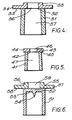
- a riser sleeve 1 having a closed top 2 and which tapers outwardly from top to bottom has a holding member in the form of a disc 3 fixed to its top 2.
- the diameter and height of the disc 3 are so chosen that a mechanical holding device can engage with the disc 3 in order to hold the sleeve 1 and place the sleeve 1 on a pattern for forming a metal casting mould, in a die for forming a pattern in the sleeve or in a metal casting mould itself.
- a riser sleeve 11 of similar shape but smaller in size than the sleeve 1 in Figure 1 has fixed to its top 12 a holding member in the form of a disc 13 of the same dimensions as the disc 3 in Figure 1. Since the two discs 3 and 13 are of the same size they can both be held by the same mechanical holding device thus enabling the same device to be used for making moulds for which the requirements for feeding castings produced in the moulds are such that different size riser sleeves are needed.
- a riser sleeve 21 has a closed top 22 and a wedge-shaped Williams core 23 formed integrally with the inner surface 24 of the top 22 and extending across a diameter of the sleeve 21 over the full inner surface 24.
- the sleeve 21 also has fixed to the outer surface 25 of its top 22 a holding member in the form of a disc 26 having a flange 27.
- the diameter of the disc 26 and its height above the flange 27 are the same as the diameters and heights of the discs 3 and 13 in Figures 1 and 2 respectively so the same mechanical holding device which is used for holding the riser sleeves in Figures 1 and 2 can engage with the disc 26 and hold the riser sleeve 21.
- Flange 27 extends beyond the outer perimeter of the riser sleeve 21 so that if desired, after the sleeve 21 has been incorporated in a ceramic shell mould by locating the sleeve 21 on a pattern, forming the ceramic shell mould around the pattern and removing the pattern, the sleeve 21 and ceramic shell mould assembly can be lifted by engaging lifting means with the underside 28 of the flange 27.
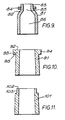
- Figure 4 shows a tapered riser sleeve 31 having an open top 32 and fixed to the top 32 a holding member in the form of a ring 33 having a flange 34.
- the outer diameter of the ring 33 and its height above the flange 34 are the same as the diameters and heights of the discs in Figures 1-3 and the riser sleeve 31 can be held by the same mechanical holding device as is used to hold the sleeves in Figures 1-3.
- the flange 34 extends beyond the perimeter of the riser sleeve 31 so that if desired the sleeve 31 can also be lifted by means engaging with the underside 35 of the flange 34.
- Aperture 36 in the ring 33 ensures that when metal is cast into a mould containing the riser sleeve 31 contact between cavity 37 in the sleeve 31 and the atmosphere is still maintained. After the metal has been cast the riser sleeve 31 and the ring 33 are removed from the riser formed in the aperture 36 and the cavity 37, and the top portion of the riser which had solidified in aperture 36 can be used for locating a holding device for mechanical handling of the casting.
- a riser sleeve 41 has fixed to its top 42 a holding member in the form of a ring 43.
- the outside diameter and height of the ring 43 are the same as the diameters and heights of the discs in Figures 1-3 and the ring in Figure 4.
- the outside edge 44 of the ring 43 extends beyond the perimeter of the sleeve 41 so that if desired the sleeve 41 can be lifted by engagement with the underside 45 of the protruding edge 44.
- the sleeve and the ring 43 are removed from the riser formed in aperture 46 and cavity 47, and the top portion of the riser which had solidified in aperture 46 can be used for locating a holding device for mechanical handling of the casting.
- Figure 6 shows a riser sleeve 51 having a closed top 52 and formed integrally with the inner surface 53 of the top 52 a conical Williams core 54.
- Sleeve 51 also has fixed to the outer surface 55 of the top 52 a holding member in the form of a ring 56 having a flange 57, both the ring 56 and the flange 57 having the same dimensions as the ring 33 and flange 34 of figure 4.
- the flange 57 extends beyond the perimeter of the sleeve 51 and if desired the sleeve can be lifted by engagement with the underside 58 of the flange 57.
- Aperture 59 in the ring 56 serves no function when the sleeve 51 is used for producing a metal casting but it is convenient to make the holding member of such a form that it is applicable to both open and closed top sleeves.
- a riser sleeve 61 has a domed top 62 and a conical Williams core 63 formed with the inner surface 64 of the domed top 62.
- the sleeve 61 also has a holding member fixed to the outer surface 65 of the domed top 62 in the form of a disc 66 having a flange 67 and a concave recess 68 in its base into which the domed top 62 fits.
- the sleeve 61 can be held by a mechanical holding device engaged with the disc 66 and the sleeve can also be lifted by means engaging with the underside 69 of the flange 67.
- Figure 8 shows a riser sleeve 71 having a flat top 72 and a wedge-shaped Williams core 73 formed integrally with the inner surface 74 at the top 72 and extending across a diameter of the sleeve 71 over the full inner surface 74.
- the sleeve 71 also has fixed to the outer surface 75 of its top 72 a holding member in the form of a hollow cylinder 76 which can be engaged by a mechanical holding device.
- Figures 1-8 show examples of riser sleeves according to the invention having holding members which are formed separately from and fixed to the sleeves, in each case the same design of riser sleeve can be achieved by integrally forming the sleeve and the holding member, thus eliminating the need to fix together the sleeve and the holding member using an adhesive, staples or nails or other similar fixing means.
- a riser sleeve 81 has an arcuate wall at its top 82 and formed integrally therewith a holding member in the form of a hollow cylinder 83 which can be engaged by a mechanical holding device. If desired the outside of the hollow cylinder 83 adjacent the top 82 of the sleeve 81 can be provided with a flange 84 as shown in the drawing, thus enabling a mould in which the sleeve 81 is incorporated to be lifted and handled by a second mechanical holding device which engages with the flange.
- the sleeve 81 and the integral hollow cylinder 83 are removed from the riser formed in hollow cylinder cavity 85 and sleeve cavity 86, and the top portion of the riser which had solidified in the cylinder cavity 85 can be used for locating a holding device for mechanical handling of the casting.
- Figure 10 shows an open-ended riser sleeve 91 whose top end 92 has a larger outside diameter and larger wall thickness than the remainder of the sleeve so as to form an integral holding member in the form of a disc 93 having a flange 94.
- a mechanical holding device can engage with the underside 95 of the flange 94.
- Figure 11 shows an open-ended riser sleeve 101 whose top and 102 has a smaller outside diameter and smaller wall thickness than the remainder of the sleeve so as to form an integral holding member in the form of a disc 103.
- a riser sleeve 111 has a top portion 112 and a bottom portion 113, and fixed to the top of the top portion 112 a holding member in the form of a disc 114 having a flange 115.
- the underside of the holding member has integrally formed therewith a wedge-shaped Williams core 116 projecting into cavity 117 in the top portion 112.
- a mechanical holding device can engage with the disc 114 in order to hold the sleeve 111 when the sleeve 111 is incorporated into a mould.
- the flange 115 extends beyond the perimeter of the top portion 112 of the sleeve 111 so that if desired, for example after the sleeve has been incorporated in the mould, the sleeve 111 and mould assembly can be lifted by engaging lifting means with the underside 118 of the flange 115.
- the sleeve 111 can be removed from the riser formed inside the sleeve 111, and because the diameter of the disc 114 and the inner diameter of the top portion 112 of the sleeve 111 are the same, the casting can then be handled mechanically by engaging the same holding device as was used during production of the mould with the top portion of the riser which had solidified in the cavity 117.
- the diameter of the body portion of the sleeve is larger than that of the top portion.
- the embodiment shown can be modified so that the diameter of the body portion is smaller than that of the top portion.
- Figure 13 shows a bottle-shaped riser sleeve 121 having a closed top or neck portion 122 and in which the neck portion 122 constitutes a holding member with which a mechanical holding device can engage in order to hold the sleeve 121 when the sleeve 121 is incorporated in a mould.
Landscapes
- Engineering & Computer Science (AREA)
- Mechanical Engineering (AREA)
- Molds, Cores, And Manufacturing Methods Thereof (AREA)
- Cylinder Crankcases Of Internal Combustion Engines (AREA)
- Shaping Of Tube Ends By Bending Or Straightening (AREA)
- Harvester Elements (AREA)
Claims (15)
Priority Applications (1)
| Application Number | Priority Date | Filing Date | Title |
|---|---|---|---|
| AT86303741T ATE45689T1 (de) | 1985-06-10 | 1986-05-16 | Speiserhuelsen fuer metallgiessformen. |
Applications Claiming Priority (2)
| Application Number | Priority Date | Filing Date | Title |
|---|---|---|---|
| GB8514647 | 1985-06-10 | ||
| GB858514647A GB8514647D0 (en) | 1985-06-10 | 1985-06-10 | Riser sleeves |
Publications (3)
| Publication Number | Publication Date |
|---|---|
| EP0206507A2 EP0206507A2 (de) | 1986-12-30 |
| EP0206507A3 EP0206507A3 (en) | 1987-07-15 |
| EP0206507B1 true EP0206507B1 (de) | 1989-08-23 |
Family
ID=10580486
Family Applications (1)
| Application Number | Title | Priority Date | Filing Date |
|---|---|---|---|
| EP86303741A Expired EP0206507B1 (de) | 1985-06-10 | 1986-05-16 | Speiserhülsen für Metallgiessformen |
Country Status (6)
| Country | Link |
|---|---|
| US (1) | US4665966A (de) |
| EP (1) | EP0206507B1 (de) |
| JP (1) | JPS61286038A (de) |
| AT (1) | ATE45689T1 (de) |
| DE (1) | DE3665139D1 (de) |
| GB (1) | GB8514647D0 (de) |
Families Citing this family (9)
| Publication number | Priority date | Publication date | Assignee | Title |
|---|---|---|---|---|
| GB2257646A (en) * | 1991-07-12 | 1993-01-20 | Hepworth Minerals & Chemicals | Riser sleeves |
| GB9220038D0 (en) * | 1992-09-22 | 1992-11-04 | Volclay Limited | Feeder sleeve |
| US5915450A (en) * | 1997-06-13 | 1999-06-29 | Ashland Inc. | Riser sleeves for custom sizing and firm gripping |
| JP3374242B2 (ja) * | 1998-10-09 | 2003-02-04 | 正光 三木 | 鋳物用発熱性アセンブリ |
| GB0030782D0 (en) * | 2000-12-18 | 2001-01-31 | Foseco Int | Feeder sleeve |
| JP4698353B2 (ja) * | 2005-09-14 | 2011-06-08 | 日本坩堝株式会社 | 押湯加熱装置 |
| KR101365021B1 (ko) * | 2013-07-25 | 2014-03-10 | 주식회사 세연에스씨에스 | 중력 주조용 금형 |
| WO2015175749A1 (en) * | 2014-05-14 | 2015-11-19 | Ask Chemicals, L.P. | Casting sleeve with williams core |
| USD872781S1 (en) | 2018-04-13 | 2020-01-14 | Foseco International Limited | Breaker core |
Family Cites Families (12)
| Publication number | Priority date | Publication date | Assignee | Title |
|---|---|---|---|---|
| US3456914A (en) * | 1965-10-23 | 1969-07-22 | Johns Manville | Inorganic fiber riser sleeves |
| US3467173A (en) * | 1966-12-14 | 1969-09-16 | Susquehanna Corp | Hot top liner |
| US3815655A (en) * | 1967-12-19 | 1974-06-11 | Exxon Research Engineering Co | Aqueous latices of high polymer compositions and means for producing same |
| CA1011083A (en) * | 1973-01-24 | 1977-05-31 | John W. Brown (Jr.) | Method and apparatus for making castings |
| DE2334501A1 (de) * | 1973-07-06 | 1975-03-20 | Eduard Dr Ing Baur | Isolierender speiser |
| DE2401508A1 (de) * | 1974-01-12 | 1975-07-24 | Eduard Dr Ing Baur | Isolierender speiser |
| US4131152A (en) * | 1976-12-30 | 1978-12-26 | Foseco Trading Ag | Feeding unit for a casting |
| DE2803247C3 (de) * | 1978-01-25 | 1981-10-08 | Rheinhold & Mahla Gmbh, 6800 Mannheim | Einstückiges Kugelspeisermodell |
| US4423762A (en) * | 1981-01-22 | 1984-01-03 | Foseco International Limited | Method for the production of a metal casting mould having a riser and a cavity former and riser sleeve for use therein |
| US4574869A (en) * | 1981-01-22 | 1986-03-11 | Foseco International Limited | Casting mould, and cavity former and sleeve for use therewith |
| DE8110973U1 (de) * | 1981-04-10 | 1981-11-19 | Foseco Gesellschaft für chemisch-metallurgische Erzeugnisse GmbH, 4280 Borken | Geschlossener speisereinsatz |
| GB2141649B (en) * | 1983-06-20 | 1986-09-03 | Steetley Refractories Ltd | Riser sleeve for metal-casting moulds |
-
1985
- 1985-06-10 GB GB858514647A patent/GB8514647D0/en active Pending
-
1986
- 1986-05-16 DE DE8686303741T patent/DE3665139D1/de not_active Expired
- 1986-05-16 EP EP86303741A patent/EP0206507B1/de not_active Expired
- 1986-05-16 AT AT86303741T patent/ATE45689T1/de active
- 1986-05-20 US US06/864,853 patent/US4665966A/en not_active Expired - Fee Related
- 1986-06-02 JP JP61129018A patent/JPS61286038A/ja active Pending
Also Published As
| Publication number | Publication date |
|---|---|
| EP0206507A2 (de) | 1986-12-30 |
| ATE45689T1 (de) | 1989-09-15 |
| JPS61286038A (ja) | 1986-12-16 |
| GB8514647D0 (en) | 1985-07-10 |
| US4665966A (en) | 1987-05-19 |
| DE3665139D1 (en) | 1989-09-28 |
| EP0206507A3 (en) | 1987-07-15 |
Similar Documents
| Publication | Publication Date | Title |
|---|---|---|
| EP0327226B1 (de) | Metallgiessformen und Trichtereinsätze mit Filterelement | |
| US6289969B1 (en) | Metal casting | |
| EP0206507B1 (de) | Speiserhülsen für Metallgiessformen | |
| US4574869A (en) | Casting mould, and cavity former and sleeve for use therewith | |
| US4240493A (en) | Shell investment casting process | |
| CA1153185A (en) | Method for the production of a metal casting mould having a riser and a cavity former and riser sleeve for use therein | |
| US4111252A (en) | Method for making molds and mold components for casting single crystal metallic articles | |
| US4133368A (en) | Single crystal casting mold and method for making same | |
| US4423762A (en) | Method for the production of a metal casting mould having a riser and a cavity former and riser sleeve for use therein | |
| RU2717433C2 (ru) | Модульная система питателя | |
| US4694884A (en) | Molten metal casting and feeder sleeves for use therein | |
| EP0265112A2 (de) | Speiserhülsen | |
| US4526338A (en) | High pressure molding riser | |
| GB2107622A (en) | Riser sleeves | |
| US3614980A (en) | Means for preventing unwanted sand dirt or other impurities from entering mold cavities prior to the pouring of the casting material | |
| US1137144A (en) | Steel manufacture. | |
| USH771H (en) | Method for casting a rotating band onto a projectile | |
| US3477683A (en) | Bottle top cap for ingot molds | |
| US2768414A (en) | Flask and mold for v-6 cylinder block | |
| EP3680041B1 (de) | Keramikgiesstrichteranordnung und verfahren zur formung solch einer anordnung | |
| JP2553916B2 (ja) | セラミックス鋳ぐるみ体の製造方法 | |
| GB2372004A (en) | A method of casting | |
| RU2060097C1 (ru) | Способ получения полого слитка | |
| RU2016697C1 (ru) | Форма для литья поршневых колец погружением | |
| JPH06170515A (ja) | 複合材料の製造方法 |
Legal Events
| Date | Code | Title | Description |
|---|---|---|---|
| PUAI | Public reference made under article 153(3) epc to a published international application that has entered the european phase |
Free format text: ORIGINAL CODE: 0009012 |
|
| AK | Designated contracting states |
Kind code of ref document: A2 Designated state(s): AT BE CH DE FR GB IT LI LU NL SE |
|
| PUAL | Search report despatched |
Free format text: ORIGINAL CODE: 0009013 |
|
| AK | Designated contracting states |
Kind code of ref document: A3 Designated state(s): AT BE CH DE FR GB IT LI LU NL SE |
|
| 17P | Request for examination filed |
Effective date: 19870608 |
|
| 17Q | First examination report despatched |
Effective date: 19881201 |
|
| GRAA | (expected) grant |
Free format text: ORIGINAL CODE: 0009210 |
|
| AK | Designated contracting states |
Kind code of ref document: B1 Designated state(s): AT BE CH DE FR GB IT LI LU NL SE |
|
| REF | Corresponds to: |
Ref document number: 45689 Country of ref document: AT Date of ref document: 19890915 Kind code of ref document: T |
|
| ITF | It: translation for a ep patent filed | ||
| REF | Corresponds to: |
Ref document number: 3665139 Country of ref document: DE Date of ref document: 19890928 |
|
| ET | Fr: translation filed | ||
| PLBE | No opposition filed within time limit |
Free format text: ORIGINAL CODE: 0009261 |
|
| STAA | Information on the status of an ep patent application or granted ep patent |
Free format text: STATUS: NO OPPOSITION FILED WITHIN TIME LIMIT |
|
| 26N | No opposition filed | ||
| PGFP | Annual fee paid to national office [announced via postgrant information from national office to epo] |
Ref country code: FR Payment date: 19920408 Year of fee payment: 7 |
|
| PGFP | Annual fee paid to national office [announced via postgrant information from national office to epo] |
Ref country code: AT Payment date: 19920409 Year of fee payment: 7 |
|
| PGFP | Annual fee paid to national office [announced via postgrant information from national office to epo] |
Ref country code: GB Payment date: 19920410 Year of fee payment: 7 |
|
| PGFP | Annual fee paid to national office [announced via postgrant information from national office to epo] |
Ref country code: SE Payment date: 19920413 Year of fee payment: 7 |
|
| PGFP | Annual fee paid to national office [announced via postgrant information from national office to epo] |
Ref country code: DE Payment date: 19920415 Year of fee payment: 7 Ref country code: BE Payment date: 19920415 Year of fee payment: 7 |
|
| PGFP | Annual fee paid to national office [announced via postgrant information from national office to epo] |
Ref country code: CH Payment date: 19920416 Year of fee payment: 7 |
|
| PGFP | Annual fee paid to national office [announced via postgrant information from national office to epo] |
Ref country code: LU Payment date: 19920429 Year of fee payment: 7 |
|
| ITTA | It: last paid annual fee | ||
| PGFP | Annual fee paid to national office [announced via postgrant information from national office to epo] |
Ref country code: NL Payment date: 19920531 Year of fee payment: 7 |
|
| EPTA | Lu: last paid annual fee | ||
| PG25 | Lapsed in a contracting state [announced via postgrant information from national office to epo] |
Ref country code: LU Free format text: LAPSE BECAUSE OF NON-PAYMENT OF DUE FEES Effective date: 19930516 Ref country code: GB Effective date: 19930516 Ref country code: AT Effective date: 19930516 |
|
| PG25 | Lapsed in a contracting state [announced via postgrant information from national office to epo] |
Ref country code: SE Effective date: 19930517 |
|
| PG25 | Lapsed in a contracting state [announced via postgrant information from national office to epo] |
Ref country code: LI Effective date: 19930531 Ref country code: CH Effective date: 19930531 Ref country code: BE Effective date: 19930531 |
|
| BERE | Be: lapsed |
Owner name: STEEL CASTINGS RESEARCH ANDT RADE ASSOCIATION Effective date: 19930531 Owner name: FOSECO INTERNATIONAL LTD Effective date: 19930531 |
|
| PG25 | Lapsed in a contracting state [announced via postgrant information from national office to epo] |
Ref country code: NL Effective date: 19931201 |
|
| GBPC | Gb: european patent ceased through non-payment of renewal fee |
Effective date: 19930516 |
|
| NLV4 | Nl: lapsed or anulled due to non-payment of the annual fee | ||
| PG25 | Lapsed in a contracting state [announced via postgrant information from national office to epo] |
Ref country code: FR Effective date: 19940131 |
|
| REG | Reference to a national code |
Ref country code: CH Ref legal event code: PL |
|
| PG25 | Lapsed in a contracting state [announced via postgrant information from national office to epo] |
Ref country code: DE Effective date: 19940201 |
|
| REG | Reference to a national code |
Ref country code: FR Ref legal event code: ST |
|
| EUG | Se: european patent has lapsed |
Ref document number: 86303741.2 Effective date: 19931210 |
|
| PG25 | Lapsed in a contracting state [announced via postgrant information from national office to epo] |
Ref country code: IT Free format text: LAPSE BECAUSE OF NON-PAYMENT OF DUE FEES;WARNING: LAPSES OF ITALIAN PATENTS WITH EFFECTIVE DATE BEFORE 2007 MAY HAVE OCCURRED AT ANY TIME BEFORE 2007. THE CORRECT EFFECTIVE DATE MAY BE DIFFERENT FROM THE ONE RECORDED. Effective date: 20050516 |