EP0205822A2 - Apparatus for manufacturing ring-pull lids - Google Patents
Apparatus for manufacturing ring-pull lids Download PDFInfo
- Publication number
- EP0205822A2 EP0205822A2 EP86105698A EP86105698A EP0205822A2 EP 0205822 A2 EP0205822 A2 EP 0205822A2 EP 86105698 A EP86105698 A EP 86105698A EP 86105698 A EP86105698 A EP 86105698A EP 0205822 A2 EP0205822 A2 EP 0205822A2
- Authority
- EP
- European Patent Office
- Prior art keywords
- tear
- brackets
- cover
- conveyor
- pairs
- Prior art date
- Legal status (The legal status is an assumption and is not a legal conclusion. Google has not performed a legal analysis and makes no representation as to the accuracy of the status listed.)
- Granted
Links
Images
Classifications
-
- B—PERFORMING OPERATIONS; TRANSPORTING
- B05—SPRAYING OR ATOMISING IN GENERAL; APPLYING FLUENT MATERIALS TO SURFACES, IN GENERAL
- B05C—APPARATUS FOR APPLYING FLUENT MATERIALS TO SURFACES, IN GENERAL
- B05C3/00—Apparatus in which the work is brought into contact with a bulk quantity of liquid or other fluent material
- B05C3/02—Apparatus in which the work is brought into contact with a bulk quantity of liquid or other fluent material the work being immersed in the liquid or other fluent material
- B05C3/09—Apparatus in which the work is brought into contact with a bulk quantity of liquid or other fluent material the work being immersed in the liquid or other fluent material for treating separate articles
- B05C3/10—Apparatus in which the work is brought into contact with a bulk quantity of liquid or other fluent material the work being immersed in the liquid or other fluent material for treating separate articles the articles being moved through the liquid or other fluent material
-
- C—CHEMISTRY; METALLURGY
- C25—ELECTROLYTIC OR ELECTROPHORETIC PROCESSES; APPARATUS THEREFOR
- C25D—PROCESSES FOR THE ELECTROLYTIC OR ELECTROPHORETIC PRODUCTION OF COATINGS; ELECTROFORMING; APPARATUS THEREFOR
- C25D13/00—Electrophoretic coating characterised by the process
- C25D13/22—Servicing or operating apparatus or multistep processes
Definitions
- the invention relates to a method for the production of tear-open covers, which consist of thin-walled, stamped and deep-drawn ferromagnetic material with a circumferential roll-on, and which have an all-round coating and a scoring or punching or punching to form the tear-open, in the case of a Punching out the tear-open opening can be equipped with a covering, sealable tear-open foil, preferably a plastic-aluminum foil.
- the all-round painting of the lids was carried out by coating the punched-out blanks of the individual lids with lacquer applied on both sides and only then the shape of the lid with the circumferential curling and the tear-open opening by means of scratches or by indentation. or the opening area was punched out before the tear-open seal was subsequently sealed in the form of the tear-off film mentioned.
- the invention has for its object to provide a method of the type mentioned in the introduction so that the coating of the cover is achieved in one operation and cut edge protection is also achieved.
- the method mentioned in the introduction is characterized in that the lid, after its shaping and scoring or after being punched in or punched out to form the tear-open opening for the purpose of painting, is moved through an electro-immersion bath and during this and during subsequent rinsing and trickling treatments is held supported with the plane of the cover mirror running in the vertical direction and only in the area of the inner wall surface of its curling.
- the intended dip coating of the already completely shaped and scored cover or provided with the stamping or punching to form the tear-open opening achieves all-round coating with increased paint application in the area of the cut edges, because the deposition of the paint component from the dip bath on the cut edges as a result of there existing greater field strength is particularly intense. Due to the provided support of the cover in the area of the inner wall surface of its curling, the support surfaces or the punctiform support points at which the paint can not be deposited are placed in an area which is covered by the sealant when the sealant is later applied to the cover curl and when Applying the lid to the container comes to lie in the inner region of the fold seam, where it is protected against external influences.
- the lid is exposed to the action of magnetic field forces during its movement through the electro-immersion bath and during the subsequent rinsing and drying treatment in order to press against the support. In this way, the cover is pressed against the bracket without a pressure element coming into contact with the cover.
- Devices for carrying out the method described above are characterized in accordance with the invention in that a conveyor is provided above an electro-immersion basin, across its length in pairs at a distance transversely to
- brackets temporarily immersed in the pool by the guide of the conveyor are held, which are equipped in pairs in each case with support fingers projecting transversely to the conveying direction for engaging in the curls mirror-image-attachable to each bracket pair, and that each row of pairs of brackets there is provided a fixed magnetic rail which extends parallel to the conveyor and extends between the brackets of the pairs arranged in series.
- the conveyor can initially have a downwardly inclined section, so that the brackets with the lids attached are immersed in the electro-immersion bath in the course of this conveying path.
- This section which is inclined downwards in the conveying direction, can be followed by a horizontal path of the conveyor, which is then followed by a section which ascends in the conveying direction in order to lift the brackets with the lids out of the immersion bath.
- the conveyor can also be guided in the area of the sink adjoining the electro-immersion bath before it leads the lid through a drying zone.
- the stationary magnetic rail is arranged and designed so that it follows the path of the conveyor. It is therefore in the electrodeposition bath or also in the subsequent rinsing bath within the liquid and acts on the cover or the cover attached to it over the entire conveying path of the cover in order to press it against the cover.
- the lids are in turn held on the support fingers projecting from the brackets, with three support fingers generally being sufficient to hold the lids securely in place on the brackets.
- the pressure forces exerted by the magnetic rail on the cover can be relatively low, since the weight of the cover is only small and also when the cover is moved by the immersion or. Rinsing bath only slight forces are exerted on the lid by the relative movement in the bath.
- pairs of brackets are each fastened to holding rods running parallel to the supporting rods. This makes it possible to arrange several pairs of brackets next to one another and in this way to utilize the entire width of the electro-immersion bath transversely to the conveying direction of the covers to be coated.
- brackets consist of straight rods which enclose a triangular surface and the support fingers are designed as rods projecting from the plane of the triangle at the corners thereof.
- the aforementioned embodiment is particularly suitable for painting covers of circular cross-section.
- the lid is attached to the respective outside of the bracket, so that the magnetic rail exerts a tensile force on the lid to be held on the bracket, by means of which the lid in turn is pressed against the outward supporting fingers of the bracket.
- an electrically conductive conveyor is used which at the same time forms the one electrode in the region of the electro-immersion bath, while the other counter-electrode is arranged on the bottom of the pool.
- the magnetic rail can either be attached via a continuous web on the pelvic floor or to corresponding holding devices outside the pelvis, or it can be held via individual supports.
- the magnetic rail is expediently designed as a permanent magnet and can therefore consist in a simple manner of individual sections lined up.
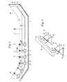
- the drawing shows a device for implementing the new method in a schematic representation.
- the electro-diving pool 1 is designed in the form of a trough and equipped on its bottom with an electrode 2 shown in dashed lines.
- a conveyor 3 shown by a dash-dotted line, which is continuously driven in the direction of arrow 4, and which is designed for example as a chain conveyor and also serves as an electrode.
- the electrode 2 which extends along the bottom of the basin 1, is connected to one pole 5 and the conveyor 3 to the other pole 6 of a direct current source 7.
- the conveyor 3 is equipped with transverse to the conveying direction support rods 8, which are held and arranged between or below the individual conveyor members so that they do not hinder the leadership of the conveyor 3 around pulleys.
- protruding bracket assemblies 9 which serve to receive finished covers 10, which are provided with an incision or punching or punching the cover mirror to form a tear-open.
- covers 10 are shown only schematically in the figures and without reproducing the prepared or completed tear-open openings.
- the conveyor 3 has above the electro-immersion basin 1 a section 3a inclined in the conveying direction and a central section running parallel and above the liquid level 18 as well as a rising section 3b adjoining in the conveying direction. In this way, they arrive during the conveying movement.
- the support rods 8 held bracket assemblies 9 with the lids 10 held thereon in the electro-immersion liquid and are lifted out of the immersion liquid again in the area of the rising section 3b.
- the bracket arrangements 9 can be seen particularly clearly from FIGS. 2 to 4.
- a number of bracket arrangements 9 can be provided in the longitudinal direction of the support rods 8, which must be spaced such that the covers 10 can be held in mirror image on both sides of the brackets.
- the brackets 11 and 12 of the pairs of brackets are each equipped with outwardly pointing support fingers 15 which, in the example shown, protrude at the corners of the brackets 12 and 13 each enclosing a triangle.
- the upper support fingers 15 are formed by extensions of the support rods 13.
- a stationary magnetic rail 16 which extends parallel to the conveyor 3 and extends between the brackets of the pairs arranged in series and which is in the basin 1 either by means of an insulated web 17 projecting to the bottom (Fig. 3) or is held by means of spaced supports.
- the magnetic rail 16 consists of a permanent magnetic material. You can out
- brackets 11 and 12 There are sections which follow the conveying path of the brackets 11 and 12 in rows and are arranged such that they always extend between the brackets 11 and 12 of each pair.
- the lid 10 When electrodeposition by passing the lid 10 through the electrodeposition bath 1, the lid 10 is coated all around, with the exception of those points at which the support fingers 15 engage the rollers 10a of the lid 10. These relatively small supporting surfaces of the curls 10a, however, lie in the area of the lid which is covered by the sealant when the sealing compound is later introduced into the curls and when the lid 10 is connected to a container opening into the interior of the between the lid and the opening edge of the container fold seam to be formed comes to rest. This practically completely eliminates the risk of corrosion in these uncoated areas. On the other hand, all other surface areas of the lid, in particular also the cut edges, are fully coated in one operation when the lid -10 is conveyed through the electro-dip bath 1.
- the further conveyance of the cover 10 by a rinsing bath arranged downstream of the electro-immersion bath can be carried out in the same way as is described in connection with FIG. 1.
- the magnetic rail 16 also extends through the subsequent rinsing bath and is also continued beyond the rinsing bath through the drying zone, so that the cover 10 on the bracket arrangements 9 until the drying process is completed due to the magnetic forces acting on them the bracket assemblies 9 are held.
Abstract
Description
Die Erfindung betrifft ein Verfahren zur Herstellung von Aufreißdeckeln, die aus dünnwandigem, durch Stanzen und Tiefziehen geformtem ferromagnetischem Werkstoff mit einer umfänglichen Anrollung bestehen, und die eine Rundumlackierung und eine Ritzung bzw. Einstanzung oder eine Ausstanzung zur Bildung der Aufreißöffnung aufweisen, wobei im Falle einer Ausstanzung der Aufreißöffnung diese mit einer abdeckenden aufsiegelbaren Aufreißfolie, vorzugsweise einer Kunststoff-Aluminiumfolie, ausrüstbar sind.The invention relates to a method for the production of tear-open covers, which consist of thin-walled, stamped and deep-drawn ferromagnetic material with a circumferential roll-on, and which have an all-round coating and a scoring or punching or punching to form the tear-open, in the case of a Punching out the tear-open opening can be equipped with a covering, sealable tear-open foil, preferably a plastic-aluminum foil.
Bei der Herstellung von Aufreißdeckeln nach dem einleitend genannten Verfahren erfolgte die Rundumlackierung der Deckel dadurch, daß die ausgestanzten Zuschnitte der einzelnen Deckel durch beidseits aufgebrachten Lack beschichtet und nachfolgend erst die Form des Deckels mit der umfänglichen Anrollung sowie der Aufreißöffnung durch Ritzen bzw. durch Ein-oder Ausstanzen des Öffnungsbereiches erfolgte, ehe im Falle der Ausstanzung anschließend der Aufreißverschluß in Form der genannten Aufreißfolie aufgesiegelt wurde.In the manufacture of tear-open lids according to the method mentioned at the outset, the all-round painting of the lids was carried out by coating the punched-out blanks of the individual lids with lacquer applied on both sides and only then the shape of the lid with the circumferential curling and the tear-open opening by means of scratches or by indentation. or the opening area was punched out before the tear-open seal was subsequently sealed in the form of the tear-off film mentioned.
Im Hinblick auf die erst nach der Lackbeschichtung des Zuschnittes erfolgte Formung des Deckels können für das bekannte Verfahren nur sehr elastische Lacke verwendet werden, die bei der notwendigen Formung des Zuschnittes nicht zu Rißstellen oder Abplatzungen neigen.With regard to the shaping of the cover only after the paint coating of the blank, only very elastic paints can be used for the known method, which do not tend to crack or flake when the blank is shaped.
Durch die nach der erfolgten Lackierung durch entsprechende Ritzung bzw. Ein-oder Ausstanzungim Deckelspiegel vorbereitete oder hergestellte Aufreißöffnung ergibt sich das weitere Problem, daß an der Ritzung bzw. an dem Öffnungsrand der Ein-oder Ausstanzung eine Schnittkante entsteht, die als freie Metalloberfläche einen besonders korrosionsgefährdeten Bereich des Deckels bildet. Aus diesem Grunde war die Benutzung von Deckeln nur im Zusammenhang mit Behältem für trockene Füllgüter möglich, falls nicht zusätzliche Maßnahmen ergriffen wurden, um die gefährdeten Bereiche mit einer korrosionsschützenden Abdeckung zu versehen. Zur Erzielung dieses Schnittkantenschutzes muß entweder eine Nachlackierung oder eine zusätzliche Abdeckung durch eine Innenfolie, d.h. eine bei aufgebrachtem Deckel auf der Behälterinnenseite befindliche Folie, vorgenommen werden, oder aber es war eine Umbördelung des Randbereiches der Ausstanzung erforderlich, damit die Schnittkante bei der Verschlußstellung des Deckels auf dem Behälter auf die Deckelaußenseite zu liegen kommt und hierdurch eine Berührung mit dem Füllgut ausgeschlossen wurde. Aber selbst außenliegende Schnittkanten sind korrosionsgefährdet, auch wenn sie durch die aufgesiegelte Abreißfolie mit abgedeckt werden.As a result of the tear opening prepared or produced after the lacquering by means of appropriate scoring or punching or punching in the cover mirror, there is the further problem that a cut edge is created on the scoring or on the opening edge of the punching or punching out, which is particularly useful as a free metal surface corrosion-prone area of the cover. For this reason, the use of lids was only possible in connection with containers for dry filling goods, unless additional measures were taken to provide the endangered areas with a corrosion-protecting cover. To achieve this cut edge protection, either a re-painting or an additional covering with an inner film, i.e. a foil located on the inside of the container when the cover is applied, or else a flanging of the edge area of the punched-out area was necessary so that the cut edge comes to rest on the outside of the cover when the cover is in the closed position and thereby prevents contact with the contents has been. But even external cut edges are at risk of corrosion, even if they are also covered by the sealed tear-off film.
Der Erfindung leigt die Aufgabe zugrunde, ein Verfahren der einleitend genannten Art so auszubilden, daß die Lackierung des Deckels in einem Arbeitsgang erreicht und dabei auch ein Schnittkantenschutz erzielt wird.The invention has for its object to provide a method of the type mentioned in the introduction so that the coating of the cover is achieved in one operation and cut edge protection is also achieved.
Zur Lösung vorstehender Aufgabe kennzeichnet sich das einleitend genannte Verfahren erfindungsgemäß dadurch, daß der Deckel nach seiner Formung und Ritzung bzw. nach der Ein-oder Ausstanzung zur Bildung der Aufreißöffnung zum Zwecke der Lackierung durch ein Elektrotauchbad hindurchbewegt und dabei sowie während nachfolgender Spül-und Tricknungsbehandlungen mit in lotrechter Richtung verlaufender Ebene des Deckelspiegels und ausschließlich im Bereich der Innenwandfläche seiner Anrollung abgestützt gehalten wird.To solve the above problem, the method mentioned in the introduction is characterized in that the lid, after its shaping and scoring or after being punched in or punched out to form the tear-open opening for the purpose of painting, is moved through an electro-immersion bath and during this and during subsequent rinsing and trickling treatments is held supported with the plane of the cover mirror running in the vertical direction and only in the area of the inner wall surface of its curling.
Durch die vorgesehene Tauchlackierung des bereits vollständig geformten und geritzten bzw. mit der Ein-oder Ausstanzung zur Bildung der Aufreißöffnung versehenen Deckels wird eine Rundumlackierung mit verstärktem Lackauftrag im Bereich der Schnittkanten erreicht, weil die Abscheidung der Lackkomponente aus dem Tauchbad an den Schnittkanten infolge der dort vorhandenen größeren Feldstärke besonders intensiv ist. Durch die vorgeehene Abstützung des Deckels im Bereich der Innenwandfläche seiner Anrollung werden die Abstützflächen bzw. die punktförmigen Abstützstellen, an denen kein Niederschlag des Lackes erfolgen kann, in einen Bereich gelegt, der beim späteren Aufbringen der Dichtungsmasse in die Deckelanrollung von der Dichtungsmasse abgedeckt und beim Aufbringen des Deckels auf den Behälter in den inneren Bereich der Falznaht zu liegen kommt, wo er gegen äußere Einflüsse geschützt untergebracht ist.The intended dip coating of the already completely shaped and scored cover or provided with the stamping or punching to form the tear-open opening achieves all-round coating with increased paint application in the area of the cut edges, because the deposition of the paint component from the dip bath on the cut edges as a result of there existing greater field strength is particularly intense. Due to the provided support of the cover in the area of the inner wall surface of its curling, the support surfaces or the punctiform support points at which the paint can not be deposited are placed in an area which is covered by the sealant when the sealant is later applied to the cover curl and when Applying the lid to the container comes to lie in the inner region of the fold seam, where it is protected against external influences.
Zweckmäßig ist es, wenn der Deckel während seiner Bewegung durch das Elektrotauchbad hindurch sowie während der nachfolgenden Spül-und Trocknungsbehandlung zum Andruck an die Abstützung der Einwirkung magnetischer Feldkräfte ausgesetzt wird. Auf diese Weise erfolgt ein Andruck der Deckel an die Bügel, ohne daß ein Andruckelement mit den Deckeln in Berührung kommt.It is expedient if the lid is exposed to the action of magnetic field forces during its movement through the electro-immersion bath and during the subsequent rinsing and drying treatment in order to press against the support. In this way, the cover is pressed against the bracket without a pressure element coming into contact with the cover.
Vorrichtungen zur Durchführung des oben beschriebenen Verfahrens kennzeichnen sich erfindungsgemäß dadurch, daß oberhalb eines Elektrotauchbeckens ein Förderer vorgesehen ist, über dessen Länge paarweise im Abstand quer zurDevices for carrying out the method described above are characterized in accordance with the invention in that a conveyor is provided above an electro-immersion basin, across its length in pairs at a distance transversely to
Förderbewegung und in Längsrichtung des Förderers fluchtend angeordnete durch die Führung des Förderers vorübergehend in das Becken eintauchende Bügel gehalten sind, die je Paar mit gegensinnig quer zur Förderrichtung vorspringenden Stützfingern zum Eingriff in die Anrollungen spiegelbildlich an jedes Bügelpaar anhängbarer Deckel ausgerüstet sind, und daß jeder Reihe von Bügelpaaren eine parallel zu dem Förderer und sich zwischen dei Bügel der in Reihe angeordneten Paare hindurch erstreckende ortsfeste Magnetschiene vorgesehen ist.Conveying movement and in the longitudinal direction of the conveyor aligned brackets temporarily immersed in the pool by the guide of the conveyor are held, which are equipped in pairs in each case with support fingers projecting transversely to the conveying direction for engaging in the curls mirror-image-attachable to each bracket pair, and that each row of pairs of brackets there is provided a fixed magnetic rail which extends parallel to the conveyor and extends between the brackets of the pairs arranged in series.
Der Förderer kann zur Überführung der Bügel mit den daran gehaltenen Deckeln in Förderrichtung zunächst einen in Richtung abwärts geneigten Abschnitt aufweisen, so daß die Bügel mit den daran befestigten Deckeln im Verlauf dieses Förderweges in das Elektrotauchbad eingetaucht werden. An diesen in Förderrichtung nach unten geneigten Abschnitt kann sich ein horizontaler Weg des Förderers anschließen, dem dann ein in Förderrichtung geneigt aufsteigender Abschnitt folgt, um die Bügel mit den Deckeln wieder aus dem Tauchbad herauszuheben. In gleicher Weise kann der Förderer auch im Bereich der sich an das Elektrotauchbad anschließenden Spülbecken geführt werden, ehe er die Deckel durch eine Trocknungszone hindurchführt. Die ortsfeste Magnetschiene ist dabei so angeordnet und ausgeführt, daß sie dem Weg des Förderers folgt. Sie liegt also in dem Elektrotauchbad bzw. auch in dem nachfolgenden Spülbad innerhalb der Flüssigkeit und wirkt über den gesamten Förderweg der Bügel bzw. der daran befestigten Deckel auf die Deckel ein, um diese gegen die Bügel zu drücken.In order to transfer the brackets with the lids held thereon in the conveying direction, the conveyor can initially have a downwardly inclined section, so that the brackets with the lids attached are immersed in the electro-immersion bath in the course of this conveying path. This section, which is inclined downwards in the conveying direction, can be followed by a horizontal path of the conveyor, which is then followed by a section which ascends in the conveying direction in order to lift the brackets with the lids out of the immersion bath. In the same way, the conveyor can also be guided in the area of the sink adjoining the electro-immersion bath before it leads the lid through a drying zone. The stationary magnetic rail is arranged and designed so that it follows the path of the conveyor. It is therefore in the electrodeposition bath or also in the subsequent rinsing bath within the liquid and acts on the cover or the cover attached to it over the entire conveying path of the cover in order to press it against the cover.
Die Deckel sind ihrerseits an den von den Bügeln vorspringenden Stützfingern gehalten, wobei in der Regel drei Stützfinger ausreichen, um die Deckel lagegesichert an den Bügeln zu halten.The lids are in turn held on the support fingers projecting from the brackets, with three support fingers generally being sufficient to hold the lids securely in place on the brackets.
Die von der Magnetschiene auf die Deckel ausgeübten Andruckkräfte können dabei relativ gering sein, da das Gewicht der Deckel nur klein ist und auch bei der Bewegung der Deckel durch das Tauch-bzw. Spülbad nur geringe Kräfte auf die Deckel durch die Relativbewegung in dem Bad ausgeübt werden.The pressure forces exerted by the magnetic rail on the cover can be relatively low, since the weight of the cover is only small and also when the cover is moved by the immersion or. Rinsing bath only slight forces are exerted on the lid by the relative movement in the bath.
Vorteilhaft ist es, wenn die Bügelpaare jeweils an parallel zu den Tragstangen verlaufenden Haltestangen befestigt sind. Hierdurch ist es möglich, mehrere Bügelpaare nebeneinander anzuordnen und auf diese Weise die gesamte Breite des Elektrotauchbades quer zur Förderrichtung der zu beschichtenden Deckel auszunutzen.It is advantageous if the pairs of brackets are each fastened to holding rods running parallel to the supporting rods. This makes it possible to arrange several pairs of brackets next to one another and in this way to utilize the entire width of the electro-immersion bath transversely to the conveying direction of the covers to be coated.
Eine besonders einfache Ausgestaltung ergibt sich, wenn die Bügel aus geraden Stäben bestehen, die eine dreieckige Fläche umschließen und die Stützfinger als an den Ecken des Dreieckes aus dessen Ebene vorspringende Stäbe ausgebildet sind.A particularly simple configuration results if the brackets consist of straight rods which enclose a triangular surface and the support fingers are designed as rods projecting from the plane of the triangle at the corners thereof.
Die vorgenannte Ausgestaltung ist besonders günstig geeignet für die Lackierung von Deckeln kreisrunden Querschnittes.The aforementioned embodiment is particularly suitable for painting covers of circular cross-section.
Die Befestigung der Deckel erfolgt auf den jeweiligen Außenseiten der Bügel, so daß die Magnetschiene auf die an den Bügeln zu haltenden Deckel eine Zugkraft ausübt, durch welche die Deckel ihrerseits gegen die nach außen gerichteten Stützfinger der Bügel gedrückt werden.The lid is attached to the respective outside of the bracket, so that the magnetic rail exerts a tensile force on the lid to be held on the bracket, by means of which the lid in turn is pressed against the outward supporting fingers of the bracket.
Besonders vorteilhaft ist es, wenn ein elektrischleitender Förderer verwendet wird, der im Bereich des Elektrotauchbades gleichzeitig die eine Elektrode bildet, während auf dem Boden des Beckens die andere Gegenelektrode angeordnet wird.It is particularly advantageous if an electrically conductive conveyor is used which at the same time forms the one electrode in the region of the electro-immersion bath, while the other counter-electrode is arranged on the bottom of the pool.
Die Magnetschiene kann entweder über einen durchgehenden Steg auf dem Beckenboden bzw. an entsprechenden Haltevorrichtungen außerhalb des Beckens befestigt sein oder aber über Einzelstützen gehalten werden. Die Magnetschiene ist zweckmäßigerweise als Dauermagnet ausgebildet und kann aus diesem Grunde in einfacher Weise aus aneinandergereihten Einzelabschnitten bestehen.The magnetic rail can either be attached via a continuous web on the pelvic floor or to corresponding holding devices outside the pelvis, or it can be held via individual supports. The magnetic rail is expediently designed as a permanent magnet and can therefore consist in a simple manner of individual sections lined up.
Die Zeichnung gibt in schematischer Darstellung eine Vorrichtung zur Durchführung des neuen Verfahrens wieder.The drawing shows a device for implementing the new method in a schematic representation.
Es zeigen:
- Fig. 1 in vereinfachter Darstellung einen Schnitt in Förderrichtung durch ein Elektrotauchbecken mit darüber angeordnetem Förderer,
- Fig 2 in perspektivischer Darstellung eine Einzelheit aus der Anordnung nach Fig. 1, jedoch ohne die Deckel,
- Fig. 3 in vergrößerter Darstellung einen Blick in Richtung des Pfeiles 111 in Fig. 1,
- Fig 4 einen Schnitt entlang der Schnittlinie IV-IV der Anordnung nach Fig. 3.
- 1 shows a simplified representation of a section in the conveying direction through an electro-immersion basin with a conveyor arranged above it,
- 2 shows a perspective view of a detail from the arrangement according to FIG. 1, but without the cover,
- 3 shows an enlarged view in the direction of arrow 111 in FIG. 1,
- 4 shows a section along the section line IV-IV of the arrangement according to FIG. 3.
In der Fig. 1 ist das Elektrotauchbecken 1 in Form einer Mulde ausgebildet und auf seinem Boden mit einer in gestrichelten Linien wiedergegebenen Elektrode 2 ausgerüstet. Oberhalb des Beckens 1 ist ein durch eine strichpunktierte Linie dargestellter Förderer 3 vorgesehen, welcher in Richtung des Pfeiles 4 kontinuierlich angetrieben wird, und der beispielsweise als Ket tenförderer ausgebildet ist und ebenfalls als Elektrode dient.In Fig. 1, the electro-diving pool 1 is designed in the form of a trough and equipped on its bottom with an
Im rechten Teil der Fig. 1 ist schematisch angedeutet, daß die Elektrode 2, welche sich entlang dem Boden des Beckens 1 erstreckt,mit dem einen Pol 5 und der Förderer 3 mit dem anderen Pol 6 einer Gleichstromquelle 7 verbunden sind.In the right part of FIG. 1 it is indicated schematically that the
Der Förderer 3 ist mit quer zur Förderrichtung verlaufenden Tragstangen 8 ausgerüstet, die zwischen oder unterhalb der einzelnen Förderglieder so gehalten und angeordnet sind, daß sie die Führung des Förderers 3 um Umlenkrollen nicht behindern.The conveyor 3 is equipped with transverse to the conveying
An den Tragstangen sind von deren Unterseite herabragende Bügelanordnungen 9 befestigt, welche zur Aufnahme von fertiggeformten Deckeln 10 dienen, die mit einer Ritzung bzw. Ein-oder Ausstanzung des Deckelspiegels zur Bildung einer Aufreißöffnung versehen sind. Diese Deckel 10 sind in den Figuren nur schematisch und ohne Wiedergabe der vorbereiteten bzw. fertiggestellten Aufreißöffnungen dargestellt.On the support rods protruding
Der Förderer 3 weist oberhalb des Elektrotauchbeckens 1 einen in Förderrichtung geneigten Abschnitt 3a sowie einen parallel und oberhalb des Flüssigkeitsniveaus 18 verlaufenden Mittelabschnitt sowie einen in Förderrichtung sich anschließenden ansteigenden Abschnitt 3b auf. Während der Förderbewegung gelangen auf diese Weise die an . den Tragstangen 8 gehaltenen Bügelanordnungen 9 mit den daran gehaltenen Deckeln 10 in die Elektrotauchflüssigkeit und werden im Bereich des ansteigenden Abschnittes 3b wieder aus der Tauchflüssigkeit herausgehoben.The conveyor 3 has above the electro-immersion basin 1 a section 3a inclined in the conveying direction and a central section running parallel and above the
Die Bügelanordnungen 9 sind besonders deutlich aus den Fig. 2 bis 4 ersichtlich. Es sind jeweils zwei Bügel 11 und 12, welche in dem dargestellten Beispiel jeweils eine dreieckige Fläche umschließen und aus Stäben bestehen, an einer Haltestange 13 befestigt, die ihrerseits über einen Verbindungsstab 14 and der Tragstange 8 gehalten sind. Dabei können in Längsrichtung der Tragstangen 8 eine Reihe von Bügelanordnungen 9 vorgesehen sein, die einen solchen Abstand aufweisen müssen, daß auf den Bügeln beiderseits spiegelbildlich die Deckel 10 gehalten werden können.The
Die Bügel 11 und 12 der Bügelpaare sind jeweils mit nach außen weisenden Stützfingem 15 ausgerüstet, welche in dem dargestellten Beispiel an den Ecken der jeweils ein Dreieck umschließenden Bügel 12 und 13 vorspringen. Die oberen Stützfinger 15 werden dabei durch Verlängerungen der Haltestangen 13 gebildet.The
Zwischen den Bügeln 11 und 12 eines jeden Paares der Anordnung ist eine parallel zu dem Förderer 3 und sich zwischen die Bügel der in Reihe angeordneten Paare hindurch erstreckende ortsfeste Magnetschiene 16 vorgesehen, die in dem Becken 1 entweder mittels eines bis zum Boden ragenden isolierten Steges 17 (Fig. 3) oder aber mittels im Abstand angeordneter Stützen gehalten ist. Die Magnetschiene 16 besteht aus einem dauermagnetischen Werkstoff. Sie kann ausProvided between the
Enzeiabschnitten bestehen, die reihenförmig dem Förderweg der Bügel 11 bzw. 12 folgen und so angeordnet sind, daß sie sich stets zwischen den Bügeln 11 und 12 eines jeden Paares erstrecken.There are sections which follow the conveying path of the
Die Fig. 3 zeigt deutlich, daß Stützfinger 15 der Bügelanordnungen 9 im Bereich der Innenwandfläche der Anrollungen 10a der Deckel 10 eingreifen, wobei die Deckel 10 in der in Fig. 3 wiedergegebenen Position durch die magnetischen Kräfte der Magnetschiene 16 gehalten bzw. gegen die Stützfinger 15 gedrückt werden.3 clearly shows that
Beim Elektrotauchlackieren durch Hindurchfördem der Deckel 10 durch das Elektrotauchbad 1 erfolgt eine Rundumbeschichtung der Deckel 10 mit Ausnahme derjenigen Stellen, an denen die Stützfinger 15 an den Anrollungen 10a der Deckel 10 angreifen. Diese relativ kleinen Stützflächen der Anrollungen 10a liegen jedoch in demjenigen Bereich des Deckels, der beim späteren Einbringen der Dichtungsmasse in die Anrollungen von der Dichtungsmasse abgedeckt wird und beim Verbinden der Deckel 10 mit einer Behälteröffnung in das Innere der zwischen dem Deckel und dem Öffnungsrand des Behälters zu bildenden Falznaht zu liegen kommt. Hierdurch wird die Gefahr einer Korrosion an diesen unbeschichteten Stellen praktisch vollständig ausgeschlossen. Alle anderen Flächenbereiche des Deckels, insbesondere auch die Schnittkanten, werden hingegen in einem Arbeitsgang beim Hindurchfördem der Deckel -10 durch das Elektrotauchbad 1 voll beschichtet.When electrodeposition by passing the
Die Weiterförderung der Deckel 10 durch ein dem Elektrotauchbad nachgeordnetes Spülbad kann in gleicher Weise vorgenommen werden, wie dies im Zusammenhang mit der Fig. 1 beschrieben ist. Zu diesem Zweck erstreckt sich die Magnetschiene 16 auch bis durch das nachfolgende Spülbad hindurch und ist fernerhin über das Spülbad hinaus weitergeführt bis durch die Trocknungszone, so daß die Deckel 10 an den Bügelanordnungen 9 bis zum Abschluß des Trocknungsvorganges aufgrund der auf sie einwirkenden Magnetkräfte sicher an den Bügelanordnungen 9 gehalten werden.The further conveyance of the
Claims (5)
Priority Applications (1)
| Application Number | Priority Date | Filing Date | Title |
|---|---|---|---|
| AT86105698T ATE45599T1 (en) | 1985-05-02 | 1986-04-24 | DEVICE FOR THE MANUFACTURE OF TEAR LID. |
Applications Claiming Priority (2)
| Application Number | Priority Date | Filing Date | Title |
|---|---|---|---|
| DE19853515672 DE3515672A1 (en) | 1985-05-02 | 1985-05-02 | METHOD AND DEVICE FOR PRODUCING Tear-off Caps |
| DE3515672 | 1985-05-02 |
Publications (3)
| Publication Number | Publication Date |
|---|---|
| EP0205822A2 true EP0205822A2 (en) | 1986-12-30 |
| EP0205822A3 EP0205822A3 (en) | 1987-06-16 |
| EP0205822B1 EP0205822B1 (en) | 1989-08-16 |
Family
ID=6269555
Family Applications (1)
| Application Number | Title | Priority Date | Filing Date |
|---|---|---|---|
| EP86105698A Expired EP0205822B1 (en) | 1985-05-02 | 1986-04-24 | Apparatus for manufacturing ring-pull lids |
Country Status (6)
| Country | Link |
|---|---|
| US (2) | US4731171A (en) |
| EP (1) | EP0205822B1 (en) |
| AT (1) | ATE45599T1 (en) |
| CA (1) | CA1282284C (en) |
| DE (2) | DE3515672A1 (en) |
| DK (1) | DK163048C (en) |
Cited By (1)
| Publication number | Priority date | Publication date | Assignee | Title |
|---|---|---|---|---|
| DE4243795A1 (en) * | 1992-12-23 | 1994-07-07 | Lechler Elring Dichtungswerke | Coating on deep drawn metal plate screen for vehicle engine compartment |
Families Citing this family (12)
| Publication number | Priority date | Publication date | Assignee | Title |
|---|---|---|---|---|
| US4908153A (en) * | 1988-05-06 | 1990-03-13 | Service Tool Die & Mfg. Company | Transport apparatus for electrocoating machines |
| KR930005013B1 (en) * | 1990-03-16 | 1993-06-11 | 다이도 메탈 고오교오 가부시기가이샤 | Method of surface-treating a half sliding bearing and apparatus for same |
| GB2246790B (en) * | 1990-08-10 | 1993-07-07 | Process Automation Internation | Electroplating apparatus |
| EP0971051A1 (en) | 1998-07-09 | 2000-01-12 | Giacomo Borra | A machine for the electrophoretic re-painting or re-varnishing of thin metal objects |
| DE19839725C1 (en) * | 1998-09-01 | 2000-03-30 | Daimler Chrysler Ag | Electrical contacting device for an electrocoating system for vehicle bodies |
| ITBO20010128A1 (en) * | 2001-03-09 | 2002-09-09 | Corima Internat Machinery S R | METHOD AND MACHINE FOR PAINTING METAL COVERS |
| DE10250471B3 (en) * | 2002-10-30 | 2004-04-01 | Lindal Ventil Gmbh | Valve plate used for aerosol containers comprises a metal sheet provided with an anticorrosion layer |
| US7622002B2 (en) * | 2006-03-15 | 2009-11-24 | Stolle Machinery Company, Llc | Spray apparatus and method for the repair of can ends |
| US7644678B2 (en) * | 2006-03-15 | 2010-01-12 | Stolle Machinery Company, Llc | Mixing apparatus and method for the repair of can ends |
| EP2599844A1 (en) * | 2011-12-02 | 2013-06-05 | PPG Industries Ohio Inc. | Coating composition for a food or beverage can |
| US10563283B2 (en) | 2016-06-24 | 2020-02-18 | Enviroleach Technologies Inc. | Methods, materials and techniques for precious metal recovery |
| US10781049B2 (en) * | 2017-06-26 | 2020-09-22 | David Christensen | Magnetic material handler |
Citations (4)
| Publication number | Priority date | Publication date | Assignee | Title |
|---|---|---|---|---|
| DE1927436A1 (en) * | 1968-06-03 | 1969-12-04 | Ford Werke Ag | Process for electrically effected coating of small objects and a suitable device for this |
| US3510022A (en) * | 1968-10-17 | 1970-05-05 | Paul H Heller | Removable tab having a protective coating |
| US3759810A (en) * | 1971-03-29 | 1973-09-18 | American Can Co | Roll through method for electro coating can ends |
| DE3120880A1 (en) * | 1981-05-26 | 1982-12-30 | Jurij Ivanovič Ageev | Installation for applying an insulating coating |
Family Cites Families (9)
| Publication number | Priority date | Publication date | Assignee | Title |
|---|---|---|---|---|
| GB435631A (en) * | 1934-05-28 | 1935-09-25 | John Kronsbein | Improvements in connection with the electro-plating of metallic articles |
| US2448116A (en) * | 1942-08-05 | 1948-08-31 | Continental Can Co | Can end treating machine |
| US2549927A (en) * | 1945-08-04 | 1951-04-24 | Ransburg Electro Coating Corp | Electrostatic detearing apparatus |
| DE1801292A1 (en) * | 1968-02-22 | 1969-09-04 | Lesonal Werke Chr Lechler & So | Device for the electrophoretic inner coating of hollow bodies |
| US3884344A (en) * | 1970-12-18 | 1975-05-20 | Ball Corp | Article conveying system |
| US4005000A (en) * | 1973-09-17 | 1977-01-25 | National Can Corporation | Electrocoating apparatus and method |
| JPS51105346A (en) * | 1975-01-20 | 1976-09-17 | Nippon Steel Corp | Iijiioopuntengaino denchakuhoshutosoho |
| JPS5933519B2 (en) * | 1977-03-11 | 1984-08-16 | 株式会社日立製作所 | holding device |
| IT8305000V0 (en) * | 1983-09-26 | 1983-09-26 | Cefin Spa | PERFECTED CONVEYOR FOR AUTOMATIC CONVEYING OF CLAMPS |
-
1985
- 1985-05-02 DE DE19853515672 patent/DE3515672A1/en not_active Withdrawn
-
1986
- 1986-04-24 AT AT86105698T patent/ATE45599T1/en not_active IP Right Cessation
- 1986-04-24 EP EP86105698A patent/EP0205822B1/en not_active Expired
- 1986-04-24 DE DE8686105698T patent/DE3665081D1/en not_active Expired
- 1986-04-30 US US06/858,938 patent/US4731171A/en not_active Expired - Fee Related
- 1986-04-30 CA CA000507999A patent/CA1282284C/en not_active Expired - Lifetime
- 1986-05-01 DK DK201286A patent/DK163048C/en not_active IP Right Cessation
-
1987
- 1987-08-14 US US07/085,970 patent/US4752172A/en not_active Expired - Fee Related
Patent Citations (5)
| Publication number | Priority date | Publication date | Assignee | Title |
|---|---|---|---|---|
| DE1927436A1 (en) * | 1968-06-03 | 1969-12-04 | Ford Werke Ag | Process for electrically effected coating of small objects and a suitable device for this |
| US3510022A (en) * | 1968-10-17 | 1970-05-05 | Paul H Heller | Removable tab having a protective coating |
| US3759810A (en) * | 1971-03-29 | 1973-09-18 | American Can Co | Roll through method for electro coating can ends |
| US3847786A (en) * | 1971-03-29 | 1974-11-12 | American Can Co | Roll-through method and apparatus for electrocoating can ends |
| DE3120880A1 (en) * | 1981-05-26 | 1982-12-30 | Jurij Ivanovič Ageev | Installation for applying an insulating coating |
Cited By (1)
| Publication number | Priority date | Publication date | Assignee | Title |
|---|---|---|---|---|
| DE4243795A1 (en) * | 1992-12-23 | 1994-07-07 | Lechler Elring Dichtungswerke | Coating on deep drawn metal plate screen for vehicle engine compartment |
Also Published As
| Publication number | Publication date |
|---|---|
| DK201286D0 (en) | 1986-05-01 |
| EP0205822B1 (en) | 1989-08-16 |
| DK163048B (en) | 1992-01-13 |
| EP0205822A3 (en) | 1987-06-16 |
| US4752172A (en) | 1988-06-21 |
| DK163048C (en) | 1992-06-09 |
| ATE45599T1 (en) | 1989-09-15 |
| CA1282284C (en) | 1991-04-02 |
| DE3515672A1 (en) | 1986-11-06 |
| DE3665081D1 (en) | 1989-09-21 |
| DK201286A (en) | 1986-11-03 |
| US4731171A (en) | 1988-03-15 |
Similar Documents
| Publication | Publication Date | Title |
|---|---|---|
| EP0205822B1 (en) | Apparatus for manufacturing ring-pull lids | |
| DE2755526A1 (en) | METHOD AND DEVICE FOR MANUFACTURING PAPER CONTAINERS | |
| CH624591A5 (en) | ||
| DE2944852C2 (en) | ||
| DE2838022A1 (en) | METHOD FOR ELECTROPOLATING AND DEVICE FOR CARRYING OUT THE METHOD | |
| EP0064948A2 (en) | Method of making lids with a closing strip which covers at least one pouring hole, particularly for beverage cans | |
| EP0251055B1 (en) | Supporting device for on both sides open ferromagnetic can bodies for transport by conveyors | |
| DE19713203C1 (en) | Device and method for surface treatment by dipping | |
| EP0716718B1 (en) | Device for electrophoretic coating of the inner surface of hollow bodies | |
| DE2428355B2 (en) | Process for filling and closing packaging containers and containers manufactured by the process | |
| EP0985746A2 (en) | Electrical contacting device for electrocoating installation for automobile bodies | |
| EP0176717B1 (en) | Clamping device for can bodies or cans open at one side for transporting on conveyors | |
| DE3202442A1 (en) | GALVANIZING APPARATUS | |
| DE10250471B3 (en) | Valve plate used for aerosol containers comprises a metal sheet provided with an anticorrosion layer | |
| DE2811245A1 (en) | DEVICE AND METHOD FOR PROCESSING THE INTERIOR SURFACES OF LARGE CONTAINERS USING ELECTRIC DISCHARGE PROCESSES | |
| DE2908574A1 (en) | DEVICE FOR ELECTRIC RESISTANCE WELDING | |
| DE324473C (en) | Method and device for guiding sheet metal through electrolytic baths | |
| DE7438691U (en) | Device for cleaning objects by applying ultrasound | |
| DE3130246A1 (en) | Bottle closure | |
| DE2010631B2 (en) | Ring-pull can lid mfr. with lacquer protection - by embossing tear lines lacquering sheet, then stamping lids out | |
| DE10234156A1 (en) | Method for transporting bulk small magnetisable items through a processing bath has a steel base with magnets over which passes a conveyor with a prismatic surface arrangement | |
| DE3510151C2 (en) | ||
| DE3513655C2 (en) | ||
| DE1532411A1 (en) | Cap-shaped lid for making a vacuum seal | |
| DE3000991A1 (en) | Tear-off metal bottle caps - are locally annealed by induction heating in inert atmosphere after application of lacquer |
Legal Events
| Date | Code | Title | Description |
|---|---|---|---|
| PUAI | Public reference made under article 153(3) epc to a published international application that has entered the european phase |
Free format text: ORIGINAL CODE: 0009012 |
|
| AK | Designated contracting states |
Kind code of ref document: A2 Designated state(s): AT BE CH DE FR GB IT LI NL SE |
|
| PUAL | Search report despatched |
Free format text: ORIGINAL CODE: 0009013 |
|
| AK | Designated contracting states |
Kind code of ref document: A3 Designated state(s): AT BE CH DE FR GB IT LI NL SE |
|
| 17P | Request for examination filed |
Effective date: 19870722 |
|
| 17Q | First examination report despatched |
Effective date: 19880629 |
|
| ITF | It: translation for a ep patent filed |
Owner name: DR. ING. A. RACHELI & C. |
|
| GRAA | (expected) grant |
Free format text: ORIGINAL CODE: 0009210 |
|
| AK | Designated contracting states |
Kind code of ref document: B1 Designated state(s): AT BE CH DE FR GB IT LI NL SE |
|
| REF | Corresponds to: |
Ref document number: 45599 Country of ref document: AT Date of ref document: 19890915 Kind code of ref document: T |
|
| REF | Corresponds to: |
Ref document number: 3665081 Country of ref document: DE Date of ref document: 19890921 |
|
| GBT | Gb: translation of ep patent filed (gb section 77(6)(a)/1977) | ||
| ET | Fr: translation filed | ||
| PLBE | No opposition filed within time limit |
Free format text: ORIGINAL CODE: 0009261 |
|
| STAA | Information on the status of an ep patent application or granted ep patent |
Free format text: STATUS: NO OPPOSITION FILED WITHIN TIME LIMIT |
|
| 26N | No opposition filed | ||
| PGFP | Annual fee paid to national office [announced via postgrant information from national office to epo] |
Ref country code: GB Payment date: 19910419 Year of fee payment: 6 Ref country code: FR Payment date: 19910419 Year of fee payment: 6 |
|
| PGFP | Annual fee paid to national office [announced via postgrant information from national office to epo] |
Ref country code: SE Payment date: 19910422 Year of fee payment: 6 |
|
| PGFP | Annual fee paid to national office [announced via postgrant information from national office to epo] |
Ref country code: CH Payment date: 19910426 Year of fee payment: 6 |
|
| ITTA | It: last paid annual fee | ||
| PGFP | Annual fee paid to national office [announced via postgrant information from national office to epo] |
Ref country code: NL Payment date: 19910430 Year of fee payment: 6 Ref country code: AT Payment date: 19910430 Year of fee payment: 6 |
|
| PGFP | Annual fee paid to national office [announced via postgrant information from national office to epo] |
Ref country code: DE Payment date: 19910620 Year of fee payment: 6 |
|
| PGFP | Annual fee paid to national office [announced via postgrant information from national office to epo] |
Ref country code: BE Payment date: 19910717 Year of fee payment: 6 |
|
| PG25 | Lapsed in a contracting state [announced via postgrant information from national office to epo] |
Ref country code: GB Effective date: 19920424 Ref country code: AT Effective date: 19920424 |
|
| PG25 | Lapsed in a contracting state [announced via postgrant information from national office to epo] |
Ref country code: SE Effective date: 19920425 |
|
| PG25 | Lapsed in a contracting state [announced via postgrant information from national office to epo] |
Ref country code: LI Effective date: 19920430 Ref country code: CH Effective date: 19920430 Ref country code: BE Effective date: 19920430 |
|
| BERE | Be: lapsed |
Owner name: SCHMALBACH-LUBECA A.G. Effective date: 19920430 |
|
| PG25 | Lapsed in a contracting state [announced via postgrant information from national office to epo] |
Ref country code: NL Effective date: 19921101 |
|
| NLV4 | Nl: lapsed or anulled due to non-payment of the annual fee | ||
| GBPC | Gb: european patent ceased through non-payment of renewal fee | ||
| PG25 | Lapsed in a contracting state [announced via postgrant information from national office to epo] |
Ref country code: FR Effective date: 19921230 |
|
| REG | Reference to a national code |
Ref country code: CH Ref legal event code: PL |
|
| PG25 | Lapsed in a contracting state [announced via postgrant information from national office to epo] |
Ref country code: DE Effective date: 19930101 |
|
| REG | Reference to a national code |
Ref country code: FR Ref legal event code: ST |
|
| EUG | Se: european patent has lapsed |
Ref document number: 86105698.4 Effective date: 19921108 |
|
| PG25 | Lapsed in a contracting state [announced via postgrant information from national office to epo] |
Ref country code: IT Free format text: LAPSE BECAUSE OF NON-PAYMENT OF DUE FEES Effective date: 20050424 |