EP0205682B1 - Klauenhammer zum Eintreiben und Ziehen von Nägeln - Google Patents
Klauenhammer zum Eintreiben und Ziehen von Nägeln Download PDFInfo
- Publication number
- EP0205682B1 EP0205682B1 EP85303941A EP85303941A EP0205682B1 EP 0205682 B1 EP0205682 B1 EP 0205682B1 EP 85303941 A EP85303941 A EP 85303941A EP 85303941 A EP85303941 A EP 85303941A EP 0205682 B1 EP0205682 B1 EP 0205682B1
- Authority
- EP
- European Patent Office
- Prior art keywords
- fulcrum member
- head
- hammer
- hammer head
- nail
- Prior art date
- Legal status (The legal status is an assumption and is not a legal conclusion. Google has not performed a legal analysis and makes no representation as to the accuracy of the status listed.)
- Expired - Lifetime
Links
- 210000000078 claw Anatomy 0.000 title claims abstract description 33
- 230000000295 complement effect Effects 0.000 claims description 18
- 230000000717 retained effect Effects 0.000 abstract description 3
- 238000000605 extraction Methods 0.000 description 17
- 210000003811 finger Anatomy 0.000 description 4
- 241000587161 Gomphocarpus Species 0.000 description 3
- 239000002023 wood Substances 0.000 description 3
- 238000013459 approach Methods 0.000 description 2
- 238000005452 bending Methods 0.000 description 2
- 238000007373 indentation Methods 0.000 description 2
- 230000035515 penetration Effects 0.000 description 2
- 241000251131 Sphyrna Species 0.000 description 1
- 229910000831 Steel Inorganic materials 0.000 description 1
- 230000015556 catabolic process Effects 0.000 description 1
- 230000006835 compression Effects 0.000 description 1
- 238000007906 compression Methods 0.000 description 1
- 230000000694 effects Effects 0.000 description 1
- 239000000284 extract Substances 0.000 description 1
- 230000002028 premature Effects 0.000 description 1
- 238000005096 rolling process Methods 0.000 description 1
- 239000010959 steel Substances 0.000 description 1
- 210000003813 thumb Anatomy 0.000 description 1
Images

Classifications
-
- B—PERFORMING OPERATIONS; TRANSPORTING
- B25—HAND TOOLS; PORTABLE POWER-DRIVEN TOOLS; MANIPULATORS
- B25C—HAND-HELD NAILING OR STAPLING TOOLS; MANUALLY OPERATED PORTABLE STAPLING TOOLS
- B25C11/00—Nail, spike, and staple extractors
-
- B—PERFORMING OPERATIONS; TRANSPORTING
- B25—HAND TOOLS; PORTABLE POWER-DRIVEN TOOLS; MANIPULATORS
- B25D—PERCUSSIVE TOOLS
- B25D1/00—Hand hammers; Hammer heads of special shape or materials
- B25D1/04—Hand hammers; Hammer heads of special shape or materials with provision for withdrawing or holding nails or spikes
- B25D1/045—Hand hammers; Hammer heads of special shape or materials with provision for withdrawing or holding nails or spikes with fulcrum member for extracting long nails
Definitions
- the invention relates to a hammer head adapted to be fixed to a hammer shaft and fitted with a claw for extracting nails from a work surface.
- Claw hammers have been used for many years for extracting nails from the work surface.
- a claw hammer is particularly useful for removing nails from the work surface, because the hammer shaft provides leverage and thus a mechanical advantage which helps in overcoming resistance of the nail being pulled from the surface.
- Difficulty can be experienced with a common claw hammer in extracting heavy long nails which have been driven so that the nail head thereof is flush with the work surface. This difficulty can be overcome by using a separate specialized nail puller with thin claws. Often long nails are bent when being extracted with a common claw hammer or nail puller.
- Patent 623,455 discloses a hammer head adapted to be fixed to a hammer shaft, the head having a face at one end for stiking a nail in order to drive the nail into a work surface and a claw device at an opposite end region for extracting a nail from the work surface, the head having a fulcrum member having an inner portion hinged to the head by a hinge assembly for relative rotation between extended and retracted positions, the hinge assembly having a hinge axis disposed normally to the hammer shaft and normally to a head axis extending between ends of the hammer head, the head also having a recess to receive the fulcrum member in the retracted position, and retaining means cooperating with the fulcrum member and the hammer head to retain the fulcrum member in the retracted position while hammering.
- nail extraction devices utilize longitudinally extending adjustable fulcrum members, typical devices being shown in U.S. Patents 524,539 (Burgess); 1,067,729 (Frey) and 2,741,456 (Williams).
- the fulcrum member of each of these three patents extend from the hammer head outwardly in the direction of the hammer shaft, and have edges which would tend to be forced into the work surface during initial extraction of the nail, thus damaging the surface.
- the longitudinal extending fulcrum member is subjected to considerable lateral loads during initial extraction and likely would bend or wear excessively when subjected to heavy use.
- fulcrum devices which are either hinged to the hammer head, or fitted for axial sliding movement relative the head, have a tendency to accidentally extend from the head during normal hammering. Also, some devices extend around side portions of the head and thus interfere with normal use of the hammert, and can prevent exceptional use of the hammer such as stiking nails with the side of the hammer head which is sometimes required when driving nails in restricted spaces.
- a hammer head of the kind known from US-A-623455 adapted to be fixed to a hammer shaft, the head having a face at one end for stiking a nail in order to drive the nail into a work surface and a claw device at an opposite end region for extracting a nail from the work surface, the head having a fulcrum member having an inner portion hinged to the head by a hinge assembly for relative rotation between extended and retracted positions, the hinge assembly having a hinge axis disposed normally to the hammer shaft and normally to a head axis extending between ends of the hammer head, the head also having a recess to receive the fulcrum member in the retracted position, and retaining means cooperating with the fulcrum member and the hammer head to retain the fulcrum member in the retracted position while hammering, the hammer head being characterized by: the fulcrum member having a fulcrum member bearing surface and the
- a portion of the bearing surface of the head has a face concentric with hinge axis to permit the relative rotation between the fulcrum member and the head about the hinge axis.
- the fulcrum member bearing surface is curved and defined by an arc; and the bearing surface of the head has a shallow S-shaped contour in which a portion thereof closest to the claw device is curved so as to be generally complementary to the arc of the fulcrum member.
- the fulcrum member bearing surface is partially generally cylindrical and defined by an arc; and the bearing surface of the head has a shallow S-shaped contour in which a portion thereof closest to the claw device is partially generally cylindrical so as to be generally complementary to the arc of the fulcrum member.
- fulcrum member has an outer portion disposed at an end of the fulcrum member generally opposite to the inner portion.
- the fulcrum member has an outer portion which has a width as measured parallel to the hinge axis greater than width of the inner portion to provide a shoulder between the inner and outer portions, the shoulder having a bearing portion to provide the fulcrum member bearing surface; and a portion of the head adjacent the recess provides the head bearing surface which is complementary to the bearing portion of the shoulder when the fulcrum member is in the extended position.
- the inner portion of the fulcrum member has spaced parallel inner and outer faces disposed inwardly of adjacent inner and outer faces of the fulcrum member to provide shoulders on either side of the inner portion, the shoulders providing the fulcrum member bearing surface; and the hammer head has a pair of spaced apart hinge bosses, the spacing between the bosses being sufficient to receive the inner portion of the fulcrum member therebetween, and portions of the hammer head adjacent the end of the spacing and the bosses providing the head bearing surface.
- the outer portion of the fulcrum member has a partially cylindrical surface having a first portion that is generally adjacent the claw device, the first portion having a relatively large radius of curvature to spread load onto the work surface when initially extracting the nail, and the partially cylindrical surface has a second portion that is further from the claw device and has a smaller radius of curvature that contacts the work surface when the nail is partially removed therefrom.
- the retaining means is characterized by a plunger member resiliently mounted within a bore of the fulcrum member for movement generally parallel to the hinge axis, the plunger having an inner portion projecting inwardly from an inner face of the fulcrum member; and the recess of the head having a main face adapted to be adjacent the inner face of the fulcrum member when the fulcrum member is in the retracted position, the main face having a plunger recess to receive the inner portion of the plunger member so as to hold the fulcrum member in the retracted position.
- the present invention provides a hammer having a head and a hammer shaft, the head having a face at one end for striking a nail in order to drive the nail into the work surface and a claw device at an opposite end region for extracting a nail from the work surface, the head having a fulcrum member having an inner portion hinged to the head by a hinge assembly for relative rotation between extended and retracted positions, the hinge assembly having a hinge axis disposed normally to the hammer shaft and normally to a head axis extending between ends of the hammer head, the head also having a recess to receive the fulcrum member in the retracted position, and retaining means cooperating with the fulcrum member and the hammer head to retain the fulcrum member in the retracted position while hammering, the hammer head being characterized by: the fulcrum member having a fulcrum member bearing surface and the hammer head having a head bearing surface, the two bearing surfaces being adapted to contact each other when
- the present invention reduces difficulties and disadvantages of the prior art by providing a hammer head in which a fulcrum member is hinged to the hammer head in such a manner that forces incurred during extraction of a nail from the work surface are transferred essentially directly to the hammer head, thus relieving the hinge assembly of excessive forces during extraction, and thus reducing a tendency of the device to fail prematurely. Also, when the hammer head is to be used for normal hammering, the fulcrum member is retracted into a recess in the head to permit normal use of the hammer without interference or a tendency for the fulcrum member to accidentally move from the retracted position.
- the fulcrum member can have projections to penetrate the work surface to prevent slippage during initial nail extraction.
- the projections can be omitted and the fulcrum member can have a periphery having a relatively large radius of curvature to contact the work surface during initial extraction of the nail, thus reducing the bearing load on the work surface.
- the reduced bearing load reduces penetration of the fulcrum member to the work surface, thus reducing or substantially eliminating damage to the work surface.
- the fulcrum member can have a relatively wide width, further reducing damage to the work surface.
- nails extracted when using the present invention correctly can be extracted with negligible bending of the nails.
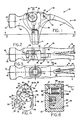
- a hammer head 10 according to the invention is shown in Figures 1 through 3 fitted to a hammer shaft 11 in a relatively conventional manner.
- the head 10 has a face 13 for striking a nail for driving the nail into a work surface, both of which are shown in Figure 7.
- the head also has a claw device 15 at an opposite end for extracting the nail from the work surface.
- the claw device has a pair of spaced claw fingers 17 and 18 which define a tapered recess 20 therebetween.
- the fingers 17 and 18 have bevelled edges 22 and 23 respectively to facilitate positioning of the fingers under the head of the nail.
- the above describes a relatively conventional claw hammer.
- the hammer head has first and second side faces 33 and 34, the face 34 being unaffected by the invention and thus is available for striking nails as is sometimes required when working in confined spaces.
- a fulcrum member 35 has an inner portion 37 hinged to the head by a hinge assembly 39.
- the hinge assembly has a hinge axis 41 disposed normally to the hammer shaft 1 and normally to a head axis 43 extending between ends of the hammer head having the face and claw device.
- the hinge assembly includes a cylindrical hinge pin 42 fixed to the head so as to be non-rotationally mounted therein and is disposed to be concentric with the hinge axis 41.
- the hinge pin can be a toughened steel shaft held to an interference fit within complementary openings in the head.
- the side face 33 of the head has a recess 45 to receive the fulcrum member in a retracted position as shown, the particular shapes of the fulcrum member and recess to be described with reference to figures 4 and 5 respectively.
- a plunger member 47 is resiliently mounted in the fulcrum member to retain the fulcrum member in the retracted position as shown and is described in greater detail with reference to Figure 6.
- the fulcrum member 35 has an outer portion 52 disposed at an end of the fulcrum member generally opposite to the inner portion 37.
- the outer portion 52 has an outer periphery 54 which is adapted to contact the work surface containing the nail when the fulcrum member is in the extended position as shown in Figure 7.
- the outer portion has an inner periphery 56 which provides a bearing surface adapted to contact the hammer head as will be described.
- the fulcrum member 35 is assumed to have a theoretical centre 58 towards which portions of the inner and outer peripheries subtend angles as will be described.
- the outer periphery 54 has a partially cylindrical surface that includes a first portion 61 which is defined by an arc 62, a second portion 63 defined by an arc 64 and a third portion 65 defined by an arc 66.
- the first portion is generally flat or has a relatively large radius of curvature, and the second and third portions have correspondingly smaller radii of curvature.
- the first portion has a plurality of projections 60 extending therefrom so as to engage the work surface as will be explained.
- the inner periphery 56 is partially generally cylindrical and defined by an arc 67 which is generally complementary to a portion of the head as will be described.
- the outer portion has a width 68 as measured parallel to the hinge axis 41, and the inner portion 37 has a width 70.
- the width 68 is greater than the width 70 to provide shoulders 71 and 72 positioned on opposite sides of the inner portion.
- the shoulders 71 and 72 have widths 73 and 74 respectively, the total of which is equal to difference in width between the inner and outer portions 37 and 52.
- the arc 67 defines a bearing portion or shoulder to provide a portion of a fulcrum member bearing surface as will be described.
- a permanent magnet 75 is fitted in a complementary recess in the face 81 of the member and is attracted to the head 10 of the hammer to assist in retaining the fulcrum member in the recess 45 and to prevent undesirable vibration when using the hammer to drive nails.
- the inner portion 37 of the fulcrum member has an opening 76 to receive the hinge pin 42, Figure 1, the opening being circular and adapted to provide a hinge bearing.
- the fulcrum member has outer and inner generally flat parallel faces 80 and 81 respectively, space between the faces defining the width 68.
- the inner portion 37 has outer and inner faces 82 and 83 which are flat and parallel to each other, and parallel to and disposed inwardly of the faces 80 and 81 to provide the shoulders 71 and 72 on either side of the inner portion.
- the plunger member 47 has an inner portion 85 which is mounted in a plunger bore 84 of the fulcrum member and is shown projecting inwardly from the inner face 81 and is described in great detail with reference to Figure 6.
- the recess 45 of the head 10 is generally complementary to the fulcrum member 37.
- the recess 45 has a main face 86 adapted to be adjacent to the inner face 81 of the fulcrum member when the fulcrum member is in the retracted position.
- the main face has a plunger recess 88 to receive the inner portion 85 of the plunger member 47 so as to hold the fulcrum member in the retracted position, as best seen in Figure 6.
- the hinge assembly 37 includes outer and inner hinge bosses 89 and 90 extending from a wall 91 of the recess and having aligned bores 92 and 93 respectively which accept complementary ends of the hinge pin 42, not shown, so as to fix the pin to the head as seen in Figure 8.
- the hinge bosses 89 and 90 have oppositely disposed inner faces which are parallel to each other and spaced apart by a spacing 96 which is sufficient to accept the inner portion 37 therebetween in both extended and retracted positions.
- the hinge bosses 89 and 90 have similar curved outer faces 94 and 95 which are generally partially cylindrical and concentric with the axis 41 of the bore to permit relative rotation between the head 10 and the member 35 about the axis 41 while maintaining close contact with the faces 94 and 95.
- the hammer head has a head bearing surface 98 which is a portion of the head remote from the handle and adjacent to and straddling an end of the spacing 96.
- the bearing surface 98 extends across the end of the spacing 96 and between the outer portions of the hinge bosses 89 and 90 and also extends to an edge of the side face 33 of the hammer.
- the head bearing surface 98 has a portion which is generally complementary to a portion of the fulcrum member bearing surface 56, the two bearing surfaces being adapted to contact each other when the fulcrum member is in the extended position as shown in Figure 7.
- the bearing surface 98 has a shallow S-shaped contour, which includes the convex and concentric portions of the faces 94 and 95 of the bosses, and concave partially cylindrical portions which are closest to the claw device and receive the inner periphery 65 of the member 35 in a fully extended position.
- the width 68 of the fulcrum member, Figure 4 is approximately equal to depth 100 of the wall 91, so that outer face 80 of the fulcrum member is generally flush with the first side face 33 of the hammer head.
- a connecting wall 102 extending between the inner face 86 and the second side face 34 has a thickness 103 which is sufficiently strong to permit the hammer to function as a conventional hammer, and yet is not excessively wide as to result in a fulcrum member having an overall width 68 much less than thickness 105 of the had of the hammer. that is a spacing between the side faces 33 and 34.
- the outer portion of the fulcrum member has a periphery having a width which approximates to width of the hammer head as measured parallel to the hinge axis.
- the wall 102 has a relieved portion 106 for an operator's finger or thumb to grip the plunger member.
- the plunger member 47 has an outer portion 107 adjacent to the relieved portion 106 of the face 80 of the fulcrum member remote from the inner face 81, the outer portion being adapted to be gripped by an operator to move the plunger member axially outwardly from the fulcrum member.
- a compression coil spring 109 extends between an end of the plunger bore 84 in the fulcrum member and a shoulder 108 of the inner portion 85 of the plunger member.
- the plunger member is forced outwardly in the direction of an arrow 112 so as to engage the recess 88 in the main face 86.
- the force in the spring can be overcome by an operator who can withdraw the inner end of the plunger member from the plunger recess to permit the fulcrum member to attain the extend position as shown in Figure 7.
- the plunger member is resiliently mounted within the bore of the fulcrum member for movement generally parallel to the hinge axis, not shown, wherein the inner portion of the plunger member projects inwardly from the inner face 81 of the fulcrum member.
- a nail 118 having a head 117 is shown extending from a work surface 119 of a piece of wood 120.
- the hammer head 10 is shown with the fulcrum member 35 positioned in the extended position, which is attained by swinging the fulcrum member from the retracted position about the axis 41 in direction of an arrow 122.
- the inner periphery or bearing surface 56 is in contact with the head bearing surface 98, but these are shown laterally spaced apart in Figure 7, and more clearly in section in Figure 8.
- the outer periphery 54 of the fulcrum member contacts the surface 119, and the second portion 63, having the intermediate radius of curvature, is shown rolling along the surface 119 as the hammer head rotated about the fulcrum member in direction of an arrow 124.
- the hammer is shown in an approximate mid position of swing relative to the surface 119 in full outline, where the nail is partially withdrawn an amount sufficient to permit the claw device 15 to be inserted under the nail head with the fulcrum member extended.
- the hammer head can swing between two extreme positions in which the surface 119 has corresponding extreme relative positions shown as broken outlines 119.1 and 119.2.
- bearing surfaces 56 and 98 are generally complementary when the fulcrum member is in the extended position.
- the complementary cylindrical bearing surfaces and clearance between the pin 42 and the opening 76 ensures intimate contact between the bearing surfaces of the fulcrum member and the head, thus relieving load from the hinge pin when extracting nails. This intimate contact provides a direct transfer of the load between the fulcrum member and hammer head which contrasts with many of the prior art devices where load from the fulcrum member or equivalent is transferred to the hinge pin which has a tendency to fail when subjected to heavy usage.
- the bearing area between the surfaces 56 and 98 is relatively large and thus bearing pressures therebetween are likely to be lower than bearing pressure encountered in contact between fulcrum members and the hammer heads of the prior art devices.
- the areas of actual contact of the bearing surfaces are disposed generally between the hinge pin and the outer periphery of the fulcrum member which is in actual contact with the work surface. This positioning also assists in relieving load from the hinge pin when extracting nails.
- the fulcrum member can remain retracted and the recess 20 of the claw device 15 is fitted adjacent the head 117, and the striking face 13 is hit with another hammer so as to drive the recess around the nail head.
- the nail can now be withdrawn partially from the wood by rotating the hammer in the usual manner.
- the hammer can be positioned so that the surface 119 is in the relative broken outline position 119.1, and the fulcrum member 35 can be extended to increase leverage.
- the first portion 61 of the outer periphery 54 is in contact with the surface 119.1 and the projections 60 penetrate the surface 119 to reduce the chances of slippage between the fulcrum member and the surface 119.
- the indentation of the wood surface is negligible for most purposes but can be eliminated in the initial stages of extraction by keeping the fulcrum member retracted until the nail has been extended a sufficient distance so that the projections do not contact the surface when the member 35 is extended.
- the contact between the fulcrum member and the surface 119 shifts so that the hammer attains the relative position shown in full outline in Figure 7, where the second surface 63 is in contact with the surface 119.
- the surface 63 has a relatively small radius of curvature, such that penetration of the fulcrum member into the surface is negligible due to the relatively large area of contact.
- the third portion 65 of the outer periphery is in contact with the work surface 119. Because the third portion 65 has a radius smaller than the second portion 63, bearing area is less but extraction forces are correspondingly less and damage to the surface 119 is usually negligible during the later stages of extraction.
- the portion 65 is relatively smooth and the surface 119 is not subjected to a sharp corner on the fulcrum member, in contrast with fulcrum members in some of the prior art devices.
- the fulcrum member 35 is inclined sufficiently towards the claw device 15 so that initial extraction forces tend to hold the fulcrum member in the extended position i.e., the fulcrum member is "over-centred” and is not subjected to a force tending to retract the fulcrum member. Any tendency of the fulcrum member to be forced into the retracted position during initial stages of nail extraction can be reduced by providing clearance in the head 10 for the member 35 to swing further towards the claw device, or to adjust the shape of the fulcrum member. In some circumstances during initial extraction of the nail the hammer head might rotate slightly relative to the fulcrum member about the axis 41 so that the actual areas in contact at any particular time will change.
- the outer periphery of the fulcrum member has a partially cylindrical surface in which, in the extended position, a first portion thereof is generally adjacent the claw device and has projections to engage the work surface when initially extracting the nail so as to prevent slippage.
- the outer periphery also has second and third portions that are further from the claw device, each having a smaller radius of curvature that contacts the work surface when the nail is partially removed therefrom.
- the portions are smoothly interconnected and there is a gradual decrease in radius of curvature to avoid sharp corners.
- the hinge pin 42 is secured to the hammer head, and the fulcrum member has the circular opening 76 to swing about the hinge pin.
- the fulcrum member can have a fixed hinge pin and the head could be provided with circular openings.
- the outer hinge boss 89 could be eliminated and the inner boss 90 and the inner portion 37 could be enlarged and repositioned to provide a simpler hinge assembly with one shoulder only on the fulcrum member.
- Use of the two spaced hinge bosses 89 and 90 is preferred for most applications because it is generally symmetrical and more sturdy.
- the hinge assembly should be constructed to ensure intimate contact between the complementary bearing surfaces, particularly as the fulcrum member approaches the fully extended position.
- the hinge pin journals the fulcrum member for limited rotation about the hammer head to ensure intimate contact between the bearing surfaces as described.
- the complementary bearing surfaces and the hinge assembly provide a load relieving means cooperating with the fulcrum member and the hammer head when the fulcrum member is in or adjacent the extended position to relieve load from the hinge assembly when extracting nails.
- the fulcrum member is retained in the recess in the retracted position by the resiliently mounted plunger member which is slidable axially in the bore.
- the magnet 75 essentially prevents relative movement when so retained, thus reducing undesirable vibration when hammering.
- An alternative retaining means can be used, for example a spring loaded ball mounted in the head of the fulcrum member to engage a complementary recess in the opposite surface. Such a ball could not be easily removed from the recess by the operator as is possible with the plunger member 47.
- a retaining means cooperates with the fulcrum member and the hammer head to retain the fulcrum member in the retracted position while hammering and various alternatives are possible.
- the projections 60 eliminate or reduce slippage between the fulcrum member and the work surface, but they penetrate soft working surfaces causing unsightly damage to the surface. If desired, the projections can be eliminated and the first portion 61 can be provided with a radious of curvature which is sufficiently large to prevent or reduce damage to the work surface.
Landscapes
- Engineering & Computer Science (AREA)
- Mechanical Engineering (AREA)
- Portable Nailing Machines And Staplers (AREA)
- Percussive Tools And Related Accessories (AREA)
Claims (10)
- Hammerkopf (10), der so aufgebaut ist, daß er an einem Hammerstiel (11) befestigt werden kann, wobei der Kopf an einem Ende eine Fläche (13), um einen Nagel (118) einzuschlagen, um den Nagel in eine Arbeitsfläche (119) zu treiben, sowie an einem gegenüberliegenden Endteil eine Klaueneinrichtung (15) besitzt, um einen Nagel aus der Arbeitsfläche (119) zu ziehen, wobei der Kopf (10) einen Drehteil (35) besitzt, der an einem inneren Teil (37) mit dem Kopf durch einen Gelenkaufbau (39) gelenkig verbunden ist, um eine relative Drehung zwischen einer ausgefahrenen und einer eingezogenen Stellung auszuführen, wobei der Gelenkaufbau (39) eine Gelenksachse (41) besitzt, die senkrecht zum Hammerstiel sowie senkrecht zu einer Kopfachse (43) angeordnet ist, die zwischen Enden des Hammerkopfs verläuft, wobei der Kopf weiters eine Ausnehmung (45), um den Drehteil (35) in der eingezogenen Stellung aufzunehmen, sowie eine Rückhalteeinrichtung (47) besitzt, die mit dem Drehteil (35) und dem Hammerkopf (10) zusammenwirkt, um den Drehteil beim Hämmern in der zurückgezogenen Stellung zurückzuhalten, wobei der Hammerkopf dadurch gekennzeichnet ist, daß:
der Drehteil (35) eine Drehteil-Auflagefläche (56) und der Hammerkopf eine Kopf-Auflagefläche (98) besitzen, wobei die beiden Auflageflächen so aufgebaut sind, um sich zu berühren, wenn sich der Drehteil in der ausgefahrenen Stellung befindet, wobei Bereiche einer tatsächlichen Berührung der Auflageflächen (56, 98) des Drehteils (35) und des Kopfs (10) nahe der Gelenksachse (41) und im allgemeinen zwischen der Gelenksachse (41) und einem Außenrand (54) des Drehteils (35) angeordnet sind, der in den meisten Hammerstellungen mit der Arbeitsfläche (119) tatsächlich in Berührung steht, um zwischen den Auflageflächen (56, 98) eine Kraft zu übertragen und den Gelenkaufbau (39) von Kräften zu entlasten, womit eine Kraftentlastung vom Gelenkaufbau (39) erfolgt, wenn Nägel herausgezogen werden. - Hammerkopf gemäß Anspruch 1, weiters dadurch gekennzeichnet, daß ein Teil (90, 94) der Auflagerfläche (98) des Kopfs (10) eine Fläche besitzt, die konzentrisch zur Gelenksachse (41) liegt, um die relative Drehung zwischen dem Drehteil (35) und dem Kopf (10) um die Gelenksachse zu ermöglichen.
- Hammerkopf gemäß Anspruch 2, weiters dadurch gekennzeichnet, daß die Drehteil-Auflagefläche (56) gekrümmt ist und von einem Bogen (67) bestimmt wird; und daß die Auflagefläche (98) des Kopfs (10) einen leicht S-förmigen Umriß besitzt, von dem ein Teil, der der Klaueneinrichtung (15) am nächsten liegt, so gekrümmt ist, daß er dem Bogen (67) des Drehteils im allgemeinen komplementär ist.
- Hammerkopf gemäß Anspruch 2, weiters dadurch gekennzeichnet, daß die Drehteil-Auflagefläche (56) teilweise im allgemeinen zylindrisch ausgebildet ist und von einem Bogen (67) bestimmt wird; und daß die Auflagefläche (98) des Kopfs (10) einen leicht S-förmigen Umriß besitzt, von dem ein Teil, der der Klaueneinrichtung (15) am nächsten liegt, teilweise im allgemeinen zylindrisch ausgebildet ist, so daß er im allgemeinen dem Bogen (67) des Drehteils komplementär ist.
- Hammerkopf gemäß Anspruch 1, weiters dadurch gekennzeichnet, daß der Drehteil (35) einen äußeren Teil (52) besitzt, der an einem Ende des Drehteils im allgemeinen gegenüber dem inneren Teil (37) angeordnet ist.
- Hammerkopf gemäß jedem der bisherigen Ansprüche, dadurch gekennzeichnet, daß der Drehteil (35) einen äußeren Teil (52) besitzt, der, gemessen parallel zur Gelenksachse (41), eine Breite (68) aufweist, die größer als die Breite des inneren Teils (37) ist, um zwischen dem inneren und äußeren Teil eine Schulter zu liefern, wobei die Schulter (71) einen Auflageteil (56) besitzt, um die Drehteil-Auflagefläche zu liefern; und daß ein Teil des Kopfs (10) neben der Ausnehmung (45) die Kopf-Auflagefläche (98) liefert, die dem Auflageteil (56) der Schulter (71) komplementär ist, wenn sich der Drehteil (35) in der ausgefahrenen Stellung befindet.
- Hammerkopf gemäß jedem der bisherigen Ansprüche, weiters dadurch gekennzeichnet, daß der innere Teil (37) des Drehteils (35) parallel beabstandete Innen- und Außenflächen (82, 83) besitzt, die innerhalb von benachbarten Innen- und Außenflächen (81, 80) des Drehteils angeordnet sind, um zu beiden Seiten des inneren Teils Schultern (71, 72) zu liefern, wobei die Schultern die Drehteil-Auflagefläche (56) liefern; und daß der Hammerkopf (10) ein Paar von beabstandeten Gelenksnaben (89, 90) besitzt, wobei der Abstand zwischen den Naben genügen groß ist, um dazwischen den inneren Teil (37) des Drehteils aufzunehmen, wobei Teile des Hammerkopfs neben dem Ende des Abstands und den Naben die Kopf-Auflagefläche (98) liefern.
- Hammerkopf gemäß jedem der bisherigen Ansprüche, dadurch gekennzeichnet, daß der äußere Teil (52) des Drehteils (35) eine teilweise zylindrische Fläche besitzt, die einen ersten Teil (61) aufweist, der im allgemeinen neben der Klaueneinrichtung (15) liegt, wobei der erste Teil (61) einen relativ großen Krümmungsradius besitzt, um eine Belastung auf die Arbeitsfläche (119) zu verteilen, wenn mit dem Herausziehen des Nagels begonnen wird, und die teilweise zylindrische Fläche einen zweiten Teil besitzt, der von der Klaueneinrichtung (15) weiter beabstandet ist und einen kleineren Krümmungsradius besitzt, der die Arbeitsfläche (119) dann berührt, wenn der Nagel teilweise aus ihr entfernt wurde.
- Hammerkopf gemäß jedem der bisherigen Ansprüche, wobei die Rückhalteeinrichtung (47) durch ein Kolbenglied (47) gekennzeichnet ist, das in einer Bohrung (84) des Drehteils (35) elastisch befestigt ist, um sich im allgemeinen parallel zur Gelenksachse (41) zu bewegen, wobei der Kolben einen inneren Teil (85) besitzt, der von einer Innenfläche (81) des Drehteils vorspringt; und wobei die Ausnehmung (45) des Kopfs (10) eine Hauptfläche (86) besitzt, die so aufgebaut ist, daß sie neben der Innenfläche (81) des Drehteils liegt, wenn sich der Drehteil in der eingezogenen Stellung befindet, wobei die Hauptfläche eine Kolbenausnehmung (88) besitzt, um den inneren Teil (85) des Kolbenglieds aufzunehmen, um den Drehteil in der eingezogenen Stellung zu halten.
- Hammer mit einem Hammerstiel (11), auf dem ein Hammerkopf (10) befestigt ist, wie er in jedem der bisherigen Ansprüche gekennzeichnet ist.
Priority Applications (4)
| Application Number | Priority Date | Filing Date | Title |
|---|---|---|---|
| US06/510,624 US4533116A (en) | 1983-07-05 | 1983-07-05 | Claw hammer for driving and extracting nails |
| EP85303941A EP0205682B1 (de) | 1985-06-04 | 1985-06-04 | Klauenhammer zum Eintreiben und Ziehen von Nägeln |
| DE8585303941T DE3583683D1 (de) | 1985-06-04 | 1985-06-04 | Klauenhammer zum eintreiben und ziehen von naegeln. |
| AT85303941T ATE65727T1 (de) | 1985-06-04 | 1985-06-04 | Klauenhammer zum eintreiben und ziehen von naegeln. |
Applications Claiming Priority (1)
| Application Number | Priority Date | Filing Date | Title |
|---|---|---|---|
| EP85303941A EP0205682B1 (de) | 1985-06-04 | 1985-06-04 | Klauenhammer zum Eintreiben und Ziehen von Nägeln |
Publications (2)
| Publication Number | Publication Date |
|---|---|
| EP0205682A1 EP0205682A1 (de) | 1986-12-30 |
| EP0205682B1 true EP0205682B1 (de) | 1991-07-31 |
Family
ID=8194244
Family Applications (1)
| Application Number | Title | Priority Date | Filing Date |
|---|---|---|---|
| EP85303941A Expired - Lifetime EP0205682B1 (de) | 1983-07-05 | 1985-06-04 | Klauenhammer zum Eintreiben und Ziehen von Nägeln |
Country Status (3)
| Country | Link |
|---|---|
| EP (1) | EP0205682B1 (de) |
| AT (1) | ATE65727T1 (de) |
| DE (1) | DE3583683D1 (de) |
Families Citing this family (1)
| Publication number | Priority date | Publication date | Assignee | Title |
|---|---|---|---|---|
| EP2687335B1 (de) | 2012-07-17 | 2014-09-24 | Nigel Carr | Werkzeugkopf zum Entfernen von Nageln und Werkzeug zum Entfernen von Nageln |
Citations (1)
| Publication number | Priority date | Publication date | Assignee | Title |
|---|---|---|---|---|
| US623455A (en) * | 1899-04-18 | Hammer |
Family Cites Families (6)
| Publication number | Priority date | Publication date | Assignee | Title |
|---|---|---|---|---|
| US1089234A (en) * | 1913-08-05 | 1914-03-03 | John Alexander Leslie | Hammer. |
| US1389101A (en) * | 1918-08-05 | 1921-08-30 | Ohrvall Oscar | Foam or froth dissipator |
| DE431425C (de) * | 1924-12-18 | 1926-07-09 | Jan Hoeksema | Vorrichtung zum Ausziehen von Drahtstiften, Naegeln o. dgl. aus Kisten, Waenden usw |
| US1664594A (en) * | 1927-04-09 | 1928-04-03 | Charles D Cummings | Claw hammer |
| US2747835A (en) * | 1954-02-23 | 1956-05-29 | Truly M Belgard | Hammer attachment |
| US4533116A (en) * | 1983-07-05 | 1985-08-06 | Drexore Resources Inc. | Claw hammer for driving and extracting nails |
-
1985
- 1985-06-04 AT AT85303941T patent/ATE65727T1/de not_active IP Right Cessation
- 1985-06-04 EP EP85303941A patent/EP0205682B1/de not_active Expired - Lifetime
- 1985-06-04 DE DE8585303941T patent/DE3583683D1/de not_active Expired - Fee Related
Patent Citations (1)
| Publication number | Priority date | Publication date | Assignee | Title |
|---|---|---|---|---|
| US623455A (en) * | 1899-04-18 | Hammer |
Also Published As
| Publication number | Publication date |
|---|---|
| DE3583683D1 (de) | 1991-09-05 |
| ATE65727T1 (de) | 1991-08-15 |
| EP0205682A1 (de) | 1986-12-30 |
Similar Documents
| Publication | Publication Date | Title |
|---|---|---|
| US4533116A (en) | Claw hammer for driving and extracting nails | |
| US7802499B2 (en) | Fastener driver | |
| US5435030A (en) | Hinge adjustment and pintle removal tool | |
| US6923432B1 (en) | Side nail puller | |
| US6351881B1 (en) | Hinge pin remover and starter | |
| US4667747A (en) | Nail starter | |
| JP2535390Y2 (ja) | 電気コネクタ等のための液圧圧着機 | |
| US7080582B2 (en) | Screwdriver tool | |
| US20040103511A1 (en) | Seal Puller | |
| US5079977A (en) | Retaining ring tools | |
| US6571666B1 (en) | Hammer loadable with different sizes of nails | |
| JPH06320444A (ja) | 工具および工具ホルダ | |
| US4717292A (en) | Drill bit | |
| EP0205682A1 (de) | Klauenhammer zum Eintreiben und Ziehen von Nägeln | |
| US7959391B2 (en) | Dry wall hand tool | |
| US7051998B2 (en) | Leverage hammer | |
| KR100287511B1 (ko) | 휴대형장치용의공구및공구홀더 | |
| CA1121578A (en) | Door pin remover | |
| CA1234384A (en) | Claw hammer for driving and extracting nails | |
| US7249752B1 (en) | Hand tool for extracting a fastener from a material | |
| US5622352A (en) | Connected arch nail puller for claw hammer | |
| US5058257A (en) | Tool for inserting and removing pin for bucket tooth | |
| US7111824B2 (en) | Tool for use with X claw hammer in removal of nails | |
| US5489178A (en) | Method and apparatus for improved masonry drive anchor | |
| CN222450163U (zh) | 撬杆 |
Legal Events
| Date | Code | Title | Description |
|---|---|---|---|
| PUAI | Public reference made under article 153(3) epc to a published international application that has entered the european phase |
Free format text: ORIGINAL CODE: 0009012 |
|
| AK | Designated contracting states |
Kind code of ref document: A1 Designated state(s): AT BE CH DE FR GB IT LI LU NL SE |
|
| 17P | Request for examination filed |
Effective date: 19870828 |
|
| RAP1 | Party data changed (applicant data changed or rights of an application transferred) |
Owner name: WALTER PANOVIC RESEARCH INCORPORATED |
|
| 17Q | First examination report despatched |
Effective date: 19881124 |
|
| GRAA | (expected) grant |
Free format text: ORIGINAL CODE: 0009210 |
|
| AK | Designated contracting states |
Kind code of ref document: B1 Designated state(s): AT BE CH DE FR GB IT LI LU NL SE |
|
| PG25 | Lapsed in a contracting state [announced via postgrant information from national office to epo] |
Ref country code: SE Effective date: 19910731 Ref country code: NL Effective date: 19910731 Ref country code: LI Effective date: 19910731 Ref country code: IT Free format text: LAPSE BECAUSE OF FAILURE TO SUBMIT A TRANSLATION OF THE DESCRIPTION OR TO PAY THE FEE WITHIN THE PRESCRIBED TIME-LIMIT;WARNING: LAPSES OF ITALIAN PATENTS WITH EFFECTIVE DATE BEFORE 2007 MAY HAVE OCCURRED AT ANY TIME BEFORE 2007. THE CORRECT EFFECTIVE DATE MAY BE DIFFERENT FROM THE ONE RECORDED. Effective date: 19910731 Ref country code: FR Effective date: 19910731 Ref country code: CH Effective date: 19910731 Ref country code: BE Effective date: 19910731 Ref country code: AT Effective date: 19910731 |
|
| REF | Corresponds to: |
Ref document number: 65727 Country of ref document: AT Date of ref document: 19910815 Kind code of ref document: T |
|
| REF | Corresponds to: |
Ref document number: 3583683 Country of ref document: DE Date of ref document: 19910905 |
|
| REG | Reference to a national code |
Ref country code: CH Ref legal event code: PL |
|
| EN | Fr: translation not filed | ||
| NLV1 | Nl: lapsed or annulled due to failure to fulfill the requirements of art. 29p and 29m of the patents act | ||
| PLBE | No opposition filed within time limit |
Free format text: ORIGINAL CODE: 0009261 |
|
| STAA | Information on the status of an ep patent application or granted ep patent |
Free format text: STATUS: NO OPPOSITION FILED WITHIN TIME LIMIT |
|
| PG25 | Lapsed in a contracting state [announced via postgrant information from national office to epo] |
Ref country code: LU Free format text: LAPSE BECAUSE OF NON-PAYMENT OF DUE FEES Effective date: 19920630 |
|
| 26N | No opposition filed | ||
| PGFP | Annual fee paid to national office [announced via postgrant information from national office to epo] |
Ref country code: GB Payment date: 19940601 Year of fee payment: 10 |
|
| PGFP | Annual fee paid to national office [announced via postgrant information from national office to epo] |
Ref country code: DE Payment date: 19940620 Year of fee payment: 10 |
|
| PG25 | Lapsed in a contracting state [announced via postgrant information from national office to epo] |
Ref country code: GB Effective date: 19950604 |
|
| GBPC | Gb: european patent ceased through non-payment of renewal fee |
Effective date: 19950604 |
|
| PG25 | Lapsed in a contracting state [announced via postgrant information from national office to epo] |
Ref country code: DE Effective date: 19960301 |