EP0205277A2 - Vehicle braking system - Google Patents
Vehicle braking system Download PDFInfo
- Publication number
- EP0205277A2 EP0205277A2 EP86303998A EP86303998A EP0205277A2 EP 0205277 A2 EP0205277 A2 EP 0205277A2 EP 86303998 A EP86303998 A EP 86303998A EP 86303998 A EP86303998 A EP 86303998A EP 0205277 A2 EP0205277 A2 EP 0205277A2
- Authority
- EP
- European Patent Office
- Prior art keywords
- vehicle
- braking
- demand
- deceleration
- gradient
- Prior art date
- Legal status (The legal status is an assumption and is not a legal conclusion. Google has not performed a legal analysis and makes no representation as to the accuracy of the status listed.)
- Granted
Links
Images

Classifications
-
- B—PERFORMING OPERATIONS; TRANSPORTING
- B60—VEHICLES IN GENERAL
- B60L—PROPULSION OF ELECTRICALLY-PROPELLED VEHICLES; SUPPLYING ELECTRIC POWER FOR AUXILIARY EQUIPMENT OF ELECTRICALLY-PROPELLED VEHICLES; ELECTRODYNAMIC BRAKE SYSTEMS FOR VEHICLES IN GENERAL; MAGNETIC SUSPENSION OR LEVITATION FOR VEHICLES; MONITORING OPERATING VARIABLES OF ELECTRICALLY-PROPELLED VEHICLES; ELECTRIC SAFETY DEVICES FOR ELECTRICALLY-PROPELLED VEHICLES
- B60L7/00—Electrodynamic brake systems for vehicles in general
-
- B—PERFORMING OPERATIONS; TRANSPORTING
- B60—VEHICLES IN GENERAL
- B60T—VEHICLE BRAKE CONTROL SYSTEMS OR PARTS THEREOF; BRAKE CONTROL SYSTEMS OR PARTS THEREOF, IN GENERAL; ARRANGEMENT OF BRAKING ELEMENTS ON VEHICLES IN GENERAL; PORTABLE DEVICES FOR PREVENTING UNWANTED MOVEMENT OF VEHICLES; VEHICLE MODIFICATIONS TO FACILITATE COOLING OF BRAKES
- B60T13/00—Transmitting braking action from initiating means to ultimate brake actuator with power assistance or drive; Brake systems incorporating such transmitting means, e.g. air-pressure brake systems
- B60T13/10—Transmitting braking action from initiating means to ultimate brake actuator with power assistance or drive; Brake systems incorporating such transmitting means, e.g. air-pressure brake systems with fluid assistance, drive, or release
- B60T13/66—Electrical control in fluid-pressure brake systems
- B60T13/662—Electrical control in fluid-pressure brake systems characterised by specified functions of the control system components
-
- B—PERFORMING OPERATIONS; TRANSPORTING
- B60—VEHICLES IN GENERAL
- B60T—VEHICLE BRAKE CONTROL SYSTEMS OR PARTS THEREOF; BRAKE CONTROL SYSTEMS OR PARTS THEREOF, IN GENERAL; ARRANGEMENT OF BRAKING ELEMENTS ON VEHICLES IN GENERAL; PORTABLE DEVICES FOR PREVENTING UNWANTED MOVEMENT OF VEHICLES; VEHICLE MODIFICATIONS TO FACILITATE COOLING OF BRAKES
- B60T13/00—Transmitting braking action from initiating means to ultimate brake actuator with power assistance or drive; Brake systems incorporating such transmitting means, e.g. air-pressure brake systems
- B60T13/10—Transmitting braking action from initiating means to ultimate brake actuator with power assistance or drive; Brake systems incorporating such transmitting means, e.g. air-pressure brake systems with fluid assistance, drive, or release
- B60T13/66—Electrical control in fluid-pressure brake systems
- B60T13/68—Electrical control in fluid-pressure brake systems by electrically-controlled valves
-
- B—PERFORMING OPERATIONS; TRANSPORTING
- B60—VEHICLES IN GENERAL
- B60T—VEHICLE BRAKE CONTROL SYSTEMS OR PARTS THEREOF; BRAKE CONTROL SYSTEMS OR PARTS THEREOF, IN GENERAL; ARRANGEMENT OF BRAKING ELEMENTS ON VEHICLES IN GENERAL; PORTABLE DEVICES FOR PREVENTING UNWANTED MOVEMENT OF VEHICLES; VEHICLE MODIFICATIONS TO FACILITATE COOLING OF BRAKES
- B60T8/00—Arrangements for adjusting wheel-braking force to meet varying vehicular or ground-surface conditions, e.g. limiting or varying distribution of braking force
- B60T8/17—Using electrical or electronic regulation means to control braking
- B60T8/1701—Braking or traction control means specially adapted for particular types of vehicles
- B60T8/1708—Braking or traction control means specially adapted for particular types of vehicles for lorries or tractor-trailer combinations
-
- B—PERFORMING OPERATIONS; TRANSPORTING
- B60—VEHICLES IN GENERAL
- B60T—VEHICLE BRAKE CONTROL SYSTEMS OR PARTS THEREOF; BRAKE CONTROL SYSTEMS OR PARTS THEREOF, IN GENERAL; ARRANGEMENT OF BRAKING ELEMENTS ON VEHICLES IN GENERAL; PORTABLE DEVICES FOR PREVENTING UNWANTED MOVEMENT OF VEHICLES; VEHICLE MODIFICATIONS TO FACILITATE COOLING OF BRAKES
- B60T8/00—Arrangements for adjusting wheel-braking force to meet varying vehicular or ground-surface conditions, e.g. limiting or varying distribution of braking force
- B60T8/26—Arrangements for adjusting wheel-braking force to meet varying vehicular or ground-surface conditions, e.g. limiting or varying distribution of braking force characterised by producing differential braking between front and rear wheels
- B60T8/266—Arrangements for adjusting wheel-braking force to meet varying vehicular or ground-surface conditions, e.g. limiting or varying distribution of braking force characterised by producing differential braking between front and rear wheels using valves or actuators with external control means
-
- B—PERFORMING OPERATIONS; TRANSPORTING
- B60—VEHICLES IN GENERAL
- B60T—VEHICLE BRAKE CONTROL SYSTEMS OR PARTS THEREOF; BRAKE CONTROL SYSTEMS OR PARTS THEREOF, IN GENERAL; ARRANGEMENT OF BRAKING ELEMENTS ON VEHICLES IN GENERAL; PORTABLE DEVICES FOR PREVENTING UNWANTED MOVEMENT OF VEHICLES; VEHICLE MODIFICATIONS TO FACILITATE COOLING OF BRAKES
- B60T8/00—Arrangements for adjusting wheel-braking force to meet varying vehicular or ground-surface conditions, e.g. limiting or varying distribution of braking force
- B60T8/32—Arrangements for adjusting wheel-braking force to meet varying vehicular or ground-surface conditions, e.g. limiting or varying distribution of braking force responsive to a speed condition, e.g. acceleration or deceleration
- B60T8/34—Arrangements for adjusting wheel-braking force to meet varying vehicular or ground-surface conditions, e.g. limiting or varying distribution of braking force responsive to a speed condition, e.g. acceleration or deceleration having a fluid pressure regulator responsive to a speed condition
- B60T8/50—Arrangements for adjusting wheel-braking force to meet varying vehicular or ground-surface conditions, e.g. limiting or varying distribution of braking force responsive to a speed condition, e.g. acceleration or deceleration having a fluid pressure regulator responsive to a speed condition having means for controlling the rate at which pressure is reapplied to or released from the brake
- B60T8/5056—Pressure reapplication using memory devices
Definitions
- the present invention relates to electrically controlled braking systems for vehicles.
- An electrically controlled braking system which includes an input transducer producing the driver's braking demands in electrical terms, a suitable electronic pressure controller, and electrical relay valves with integral pressure transducers on each axle of the vehicle.
- the system includes a pressure control loop taking an input signal from the brake pedal transducer which is used to provide a pressure error signal by comparison with a pressure transducer output signal, this pressure error forming the input to a pressure controller which generates an output signal which causes the pressure developed by an electro-pneumatic or electro-hydraulic converter to change in a direction such as to reduce the pressure error amplitude.
- an electronically controlled braking system in which vehicle load measurements, made dynamically, are used to modify the braking demand, individually for each axle and in which, under preset conditions of speed, braking level and operating gradient, the error formed between braking demand and measured vehicle deceleration is used gradually, over a number of stops, to adapt braking pressures to restore expected braking performance.
- no correction based on deceleration error is made during a vehicle stop but a summation of previous errors is arranged to cause a small increment in brake pressure correction to be applied after each stop until said error formed under the preset conditions falls to zero.
- braking pressure constants are compensated by introducing a demand offset in response to vehicle gradient, said operating gradient being measured as an equivalent deceleration, by comparison of an on-board deceleration transducer and the corresponding figure generated by measuring the rate of change of wheel speeds.
- the gradient correction can be made at low speeds but based on data which was obtained at speeds above a preset low limit and which is inhibited at very low braking demands.
- the gradient correction can provide a demand offset but is never allowed to exceed the actual driver demand in amplitude and at very low demands is reduced to zero.
- the adaptive constant slowly built up over a series of vehicle stops is used to form a vehicle brake performance figure to be output by the system via a diagnostic port on demand.
- the adaptive constant can be monitored against a preset level, brake deficiency being signalled if this level is exceeded.
- a foot pedal transducer In a compensated braking system a foot pedal transducer generates a first signal indicating the braking level desired by the driver and additional sensors measure the vehicle axle loads and the operating gradient. The system makes appropriate open loop corrections to the brake pressure demands being interpreted from the driver pedal input with the aim of restoring the vehicle deceleration to be fixed in proportion to the driver's demand.
- a pressure control loop 10 taking an input D from a brake pedal transducer 12 which is used to provide a pressure error signal E by comparison in an adder/subtractor 14 with a pressure transducer output signal P, this pressure error E forming the input to a pressure controller 16 which generates an output signal which causes the pressure developed by an electro-pneumatic or electro-hydraulic converter 18 to change in a direction such as to reduce the amplitude of the pressure error E.
- Pneumatic or hydraulic pressure medium is stored in a reservoir 20.
- a pressure controller 16 depends upon the type of converter 18 employed. Two such converter principles are well known, namely an analogue system in which a valve is employed with pressure output developed proportional to solenoid current and a digital system, as shown in Fig.1, in which a pair of simpler solenoid valves 20a, 20b is employed to raise or lower a control chamber pressure by selective energisation.
- One form of pneumatic converter employs a relay valve 22 which responds .to this control chamber pressure and which re-balances into the closed condition when the brake pressures at the actuators 24a, 24b for the brakes 26a, 26b - (left and right) of the vehicle become equal to this control pressure.
- Such a valve 22 has an advantage in that the control chamber pressure responds rapidly to valve opening giving a fast control loop which is accurate and responsive.
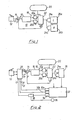
- Fig.2 illustrates a compensated braking system in accordance with the present invention which comprises closed loop controllers of the type shown in Fig.1 which are separate for each axle or for each wheel and which are supplied with pressure demands D by a braking correction sub-system 28 such that front and rear systems may receive different pressure demands D F , D R for equal braking inputs.
- the main sources of braking parameter change are measured and the pressure demands to the inner closed loop pressure systems are adjusted to compensate for these measured changes. This leaves the remaining principal sources of system drift within the brakes themselves so that errors measured are an indication of brake condition and can be used to slowly adapt the relationship between brake demand and brake application pressures. As explained- in detail below, this adaptation is arranged to take place over a sequence of many stops that the vehicle makes, but with no adaptive changes taking place during the course of each stop.
- the main sources of braking system disturbance are vehicle load and operating gradient, both of which can change suddenly, and brake deterioration which is much more gradual.
- the sudden changes require compensation by corresponding sudden corrections whilst slow changes can be countered by a gradual adaptation over a time period which can extend into days or weeks depending on vehicle usage.
- axle load readings L F , L R generated by additional transducers 30a, 30b - (front and rear) on the vehicle 32, are used as correction inputs and for each axle form a pressure constant expressed in psi/ton/g.
- this is achieved by the use of a digital mutliplier which forms a suitably scaled product of pedal input demand D and axle load measurement L, to form the pressure demand figure D R , DF.
- the other main disturbance to braking caused by gradient can be determined by a comparison between deceleration as sensed by a vehicle decelerometer 34 and figures generated from speeds sensed by speed sensors 36 at the vehicle wheels and differentiated electronically in a gradient determination means 38 after being combined to form a vehicle reference signal in a manner which is well known in anti-lock systems (see Fig.5 and corresponding description).
- the gradient figure G generated is a decelerated error with a sign which indicates uphill or downhill and which can be added directly to braking demand D to achieve appropriate correction.
- very low demand levels where check braking is being called for example where the vehicle is travelling downhill at a constant speed and.
- the gradient compensation offset is arranged to be reduced so that at no time is it allowed to exceed the actual driver demand, so as to prevent input cancellation or any step disturbance to braking as demand is gradually increased.
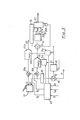
- Fig.3 shows more detail of an example of a compensated braking controller in accordance with this invention where compensating input signals are- derived from load measurements on each axle and gradient signals are provided by a gradient detector as in Fig.2. Only the rear pressure channel is illustrated fully in Fig.3, the front pressure channel being essentially the same and therefore being largely omitted for simplification of the drawings.
- Front and rear channel demand signals D from the brake demand transducer 12 are added in respective adders 39a, 39b to the gradient correction signals G c from a correction calculating means 40 and supplied as first inputs to respective front and rear digital multipliers 42a, 42b.
- Deceleration demand signals from the demand transducer 12 are also, after filtering in a filter 44, compared in an adder/subtractor 46 with deceleration feedback signals F from a vehicle decelerometer (not shown) to form a deceleration error signal F E which is supplied to a calculation means 48 for providing a long term adaptive constant C for the vehicle brakes.
- a filter 44 compared in an adder/subtractor 46 with deceleration feedback signals F from a vehicle decelerometer (not shown) to form a deceleration error signal F E which is supplied to a calculation means 48 for providing a long term adaptive constant C for the vehicle brakes.
- a controllable switch 50 is adapted to permit the passage of the deceleration error F E to the long term adaptive constant calculating means 48 only when a control signal S from a gate 52 indicates the receipt of signals from a sensor 54 responsive to the demand being greater than a first predetermined level, a sensor 56 responsive to the gradient being in a zero band, a sensor 58 responsive to the speed being greater than a first predetermined threshold, a sensor 60 responsive to the demand being less than a second predetermined level and a sensor 62 responsive to the vehicle speed being less than a second predetermined threshold.
- the switch inhibits the deceleration error from reaching the circuit 48.
- the switch 50 also inhibits the deceleration error on receipt of a signal from an anti-lock detection means 64.
- the long term adaptive constant producing means 48 includes a very slow integrating means 66 whose output is connected via a switch 68 to a sample averaging means 70, the switch 67 being controlled in response to an End of STOP Pulse provided on a line 72 at the end of each vehicle stop. It should be pointed out, however, that the block diagrams showing the long term adaptive constant being derived from deceleration error are an attempt to illustrate in simple terms what in practice would be achieved with software.
- the integrator 66 of Fig.4 can be simulated by a digital computer using an accumulating memory location which receives the addition of processed deceleration errors at regular preset intervals-
- the integrator can be reset at any point in time, to a preset starting point such as unity, or -a scaled value representing unity.
- the integral correction developed at the end of any stop (or at the low speed point at which the correction changes are discontinued) can be determined by calculation of the difference between the integrator final reading and the stored integrator start figure.
- the integrating location can be reset to the stored integral start figure.
- This may be a preset base figure or may altematively be a progressive figure formed from the previous integral start level plus a percentage of the integral correction developed during the stop. If this is the case, the stored integrator start figure is changed after each stop and control is thereby adapted to suit braking conditions.
- the routine is as shown below.
- the resulting long term adaptive constant C is applied to the second inputs of the multipliers 42a, 42b by way of respective load apportioning circuits 74a, 74b adapted to modify the long term adaptive constant C in dependence upon the prevailing vehicle load figures L R , L F , received from the load sensors 30a, 30b and supplied via the element 40.
- the prevailing gradient on which the vehicle is operating is calculated in a circuit 78 from signals received from a vehicle decelerometer 80 and from signals from a wheel speed sensor 82, differentiated at 84.
- Circuit 78 also receives a limiting signal from a low-speed threshold device 91 whenever the correction has a tendency to exceed the driver's demand.
- Gradient corrected demand is obtained from the adder 39 on a line 43. The gradient is obtained by taking the difference between:-
- the resulting output is used to form the axle- pressure demands D F or D R to the pressure controllers.
- One remaining input to the pressure controller can be an anti-lock pressure override signal obtained from a separate skid detector 76, possibly incorporated within the same controller.
- braking will be much more repeatable than with non-controlled vehicles.
- the driver demand will be related to achieved vehicle deceleration and comparison of these signals, demand and deceleration, can be expected to show good agreement unless braking constants change due to brake factor changes.
Abstract
Description
- The present invention relates to electrically controlled braking systems for vehicles.
- An electrically controlled braking system is known which includes an input transducer producing the driver's braking demands in electrical terms, a suitable electronic pressure controller, and electrical relay valves with integral pressure transducers on each axle of the vehicle. The system includes a pressure control loop taking an input signal from the brake pedal transducer which is used to provide a pressure error signal by comparison with a pressure transducer output signal, this pressure error forming the input to a pressure controller which generates an output signal which causes the pressure developed by an electro-pneumatic or electro-hydraulic converter to change in a direction such as to reduce the pressure error amplitude.
- It is an object of the present invention to provide an electrically controlled braking system of this type having improved braking control characteristics in relation to known systems.
- In accordance with the present invention, there is provided an electronically controlled braking system in which vehicle load measurements, made dynamically, are used to modify the braking demand, individually for each axle and in which, under preset conditions of speed, braking level and operating gradient, the error formed between braking demand and measured vehicle deceleration is used gradually, over a number of stops, to adapt braking pressures to restore expected braking performance.
- Preferably, no correction based on deceleration error is made during a vehicle stop but a summation of previous errors is arranged to cause a small increment in brake pressure correction to be applied after each stop until said error formed under the preset conditions falls to zero.
- Advantageously, braking pressure constants are compensated by introducing a demand offset in response to vehicle gradient, said operating gradient being measured as an equivalent deceleration, by comparison of an on-board deceleration transducer and the corresponding figure generated by measuring the rate of change of wheel speeds.
- In the latter system, the gradient correction can be made at low speeds but based on data which was obtained at speeds above a preset low limit and which is inhibited at very low braking demands. The gradient correction can provide a demand offset but is never allowed to exceed the actual driver demand in amplitude and at very low demands is reduced to zero.
- Preferably, the adaptive constant slowly built up over a series of vehicle stops is used to form a vehicle brake performance figure to be output by the system via a diagnostic port on demand. The adaptive constant can be monitored against a preset level, brake deficiency being signalled if this level is exceeded.
- The invention is described further hereinafter, by way of example only, with reference to the accompanying drawings, in which:-
- Fig.1 is a diagrammatic illustration of a known electrically controlled braking system for vehicles;
- Fig.2 is a generalised illustration of one embodiment of a braking system in accordance with the present invention;
- Fig.3 is a more detailed illustration of an embodiment in accordance with the present invention;
- Fig.4 illustrates diagrammatically one means for achieving the long term adaptive constant in the system of Fig.3; and
- Fig.5 illustrates one means of achieving a gradient corrected demand signal.
- In a compensated braking system a foot pedal transducer generates a first signal indicating the braking level desired by the driver and additional sensors measure the vehicle axle loads and the operating gradient. The system makes appropriate open loop corrections to the brake pressure demands being interpreted from the driver pedal input with the aim of restoring the vehicle deceleration to be fixed in proportion to the driver's demand.
- Referring now to Fig.1, there is shown a known system which employs a
pressure control loop 10 taking an input D from abrake pedal transducer 12 which is used to provide a pressure error signal E by comparison in an adder/subtractor 14 with a pressure transducer output signal P, this pressure error E forming the input to apressure controller 16 which generates an output signal which causes the pressure developed by an electro-pneumatic or electro-hydraulic converter 18 to change in a direction such as to reduce the amplitude of the pressure error E. Pneumatic or hydraulic pressure medium is stored in areservoir 20. - The nature and circuit of such a
pressure controller 16 depends upon the type ofconverter 18 employed. Two such converter principles are well known, namely an analogue system in which a valve is employed with pressure output developed proportional to solenoid current and a digital system, as shown in Fig.1, in which a pair ofsimpler solenoid valves relay valve 22 which responds .to this control chamber pressure and which re-balances into the closed condition when the brake pressures at theactuators 24a, 24b for thebrakes valve 22 has an advantage in that the control chamber pressure responds rapidly to valve opening giving a fast control loop which is accurate and responsive. - Fig.2 illustrates a compensated braking system in accordance with the present invention which comprises closed loop controllers of the type shown in Fig.1 which are separate for each axle or for each wheel and which are supplied with pressure demands D by a
braking correction sub-system 28 such that front and rear systems may receive different pressure demands DF, D R for equal braking inputs. - In the present system, as an alternative strategy to closing the deceleration loop for the vehicle, the main sources of braking parameter change are measured and the pressure demands to the inner closed loop pressure systems are adjusted to compensate for these measured changes. This leaves the remaining principal sources of system drift within the brakes themselves so that errors measured are an indication of brake condition and can be used to slowly adapt the relationship between brake demand and brake application pressures. As explained- in detail below, this adaptation is arranged to take place over a sequence of many stops that the vehicle makes, but with no adaptive changes taking place during the course of each stop.
- The main sources of braking system disturbance are vehicle load and operating gradient, both of which can change suddenly, and brake deterioration which is much more gradual. The sudden changes require compensation by corresponding sudden corrections whilst slow changes can be countered by a gradual adaptation over a time period which can extend into days or weeks depending on vehicle usage.
- As indicated in Fig.2, axle load readings LF, L R, generated by
additional transducers 30a, 30b - (front and rear) on thevehicle 32, are used as correction inputs and for each axle form a pressure constant expressed in psi/ton/g. As explained in more detail below in connection with Fig.3, this is achieved by the use of a digital mutliplier which forms a suitably scaled product of pedal input demand D and axle load measurement L, to form the pressure demand figure DR, DF. - The other main disturbance to braking caused by gradient can be determined by a comparison between deceleration as sensed by a
vehicle decelerometer 34 and figures generated from speeds sensed by speed sensors 36 at the vehicle wheels and differentiated electronically in a gradient determination means 38 after being combined to form a vehicle reference signal in a manner which is well known in anti-lock systems (see Fig.5 and corresponding description). The gradient figure G generated is a decelerated error with a sign which indicates uphill or downhill and which can be added directly to braking demand D to achieve appropriate correction. As explained in detail hereinafter, at very low demand levels where check braking is being called, (for example where the vehicle is travelling downhill at a constant speed and. braking demand is not intended to produce any appreciable deceleration), this addition is arranged to be inhibited and similar inhibition may be deliberately caused at low speed or may be based on gradient signals stored as the speed falls through a preset low speed band. Furthermore, at light braking demands, the gradient compensation offset is arranged to be reduced so that at no time is it allowed to exceed the actual driver demand, so as to prevent input cancellation or any step disturbance to braking as demand is gradually increased. - Fig.3 shows more detail of an example of a compensated braking controller in accordance with this invention where compensating input signals are- derived from load measurements on each axle and gradient signals are provided by a gradient detector as in Fig.2. Only the rear pressure channel is illustrated fully in Fig.3, the front pressure channel being essentially the same and therefore being largely omitted for simplification of the drawings.
- Front and rear channel demand signals D from the
brake demand transducer 12 are added inrespective adders means 40 and supplied as first inputs to respective front and reardigital multipliers demand transducer 12 are also, after filtering in afilter 44, compared in an adder/subtractor 46 with deceleration feedback signals F from a vehicle decelerometer (not shown) to form a deceleration error signal FE which is supplied to a calculation means 48 for providing a long term adaptive constant C for the vehicle brakes. As illustrated in more detail in Fig. 4. acontrollable switch 50 is adapted to permit the passage of the deceleration error FE to the long term adaptiveconstant calculating means 48 only when a control signal S from agate 52 indicates the receipt of signals from asensor 54 responsive to the demand being greater than a first predetermined level, asensor 56 responsive to the gradient being in a zero band, a sensor 58 responsive to the speed being greater than a first predetermined threshold, a sensor 60 responsive to the demand being less than a second predetermined level and a sensor 62 responsive to the vehicle speed being less than a second predetermined threshold. In the absence of the signals, the switch inhibits the deceleration error from reaching thecircuit 48. Theswitch 50 also inhibits the deceleration error on receipt of a signal from an anti-lock detection means 64. - The long term adaptive
constant producing means 48 includes a veryslow integrating means 66 whose output is connected via a switch 68 to a sample averaging means 70, theswitch 67 being controlled in response to an End of STOP Pulse provided on aline 72 at the end of each vehicle stop. It should be pointed out, however, that the block diagrams showing the long term adaptive constant being derived from deceleration error are an attempt to illustrate in simple terms what in practice would be achieved with software. - By way of example, the
integrator 66 of Fig.4 can be simulated by a digital computer using an accumulating memory location which receives the addition of processed deceleration errors at regular preset intervals- The integrator can be reset at any point in time, to a preset starting point such as unity, or -a scaled value representing unity. The integral correction developed at the end of any stop (or at the low speed point at which the correction changes are discontinued) can be determined by calculation of the difference between the integrator final reading and the stored integrator start figure. - Thus at the end of each stop, the integrating location can be reset to the stored integral start figure. This may be a preset base figure or may altematively be a progressive figure formed from the previous integral start level plus a percentage of the integral correction developed during the stop. If this is the case, the stored integrator start figure is changed after each stop and control is thereby adapted to suit braking conditions.
- Example -Suppose the unity figure is 128. This is the base SISF. Integral correction = Integrator reading, In -Stored integrator start figure SISF.
- The routine is as shown below.

- The resulting long term adaptive constant C, updated at the end of each stop, is applied to the second inputs of the
multipliers load apportioning circuits 74a, 74b adapted to modify the long term adaptive constant C in dependence upon the prevailing vehicle load figures LR, LF, received from theload sensors 30a, 30b and supplied via theelement 40. - As indicated in Fig.5, the prevailing gradient on which the vehicle is operating is calculated in a
circuit 78 from signals received from avehicle decelerometer 80 and from signals from awheel speed sensor 82, differentiated at 84.Circuit 78 also receives a limiting signal from a low-speed threshold device 91 whenever the correction has a tendency to exceed the driver's demand. Gradient corrected demand is obtained from theadder 39 on aline 43. The gradient is obtained by taking the difference between:- - a) Rate of change of wheel speed, and
- b) Vehicle decelerometer output.
- This results because, on a gradient, the suspended mass of the decelerometer suffers a gravity induced offset (which is algebraically additive to any deceleration/acceleration which is taking place. This offset is best envisaged in the static condition, pointing downhill, where it represents the equivalent deceleration being applied to the vehicle to prevent a totally free body adopting an acceleration resulting from the gradient induced continuous speed increase. The difference between the two signals is therefore in acceleration terms and must be added to the demand (deceleration) signals being produced by the driver. On downhill slopes these signals are added to the driver demand to generate extra braking, and on uphill slopes are subtracted from the demand, as less braking is required. It should be noted that at no time is this gradient correction allowed to exceed the demand, this being the purpose of
amplitude limiter 81 which receives a reference input from the driver demand and which reduces the correction to zero at very low demand levels. Thus, on flat ground the two measuring systems always generate equal signals, even under deceleration and acceleration conditions. - Thus, referring back to Fig.3, input demands D produced by the brake pedal are added at the
adder 39 to the two gradient correction signals Gc, which will be nominally equal but are separate in that they are supplied to the two (or more) axle control channels which are provided to maintain the accepted split-braking standards. There are certain circumstances in which equal correction front and rear is not warranted and the signal processing will be effected in the correction calculator which has access to the axle load signals. Gradient corrected demands are used to form the inputs to each axle multiplier 42 where the adaptive adjustment and load corrections are made by multiplying each input by a local Pressure Modification Factor (PMF), given by: PMF = Vehicle Adaptive Constant C x Axle Load Correction Factor. The resulting output, suitably scaled for compatibility with the pressure transducer output range, is used to form the axle- pressure demands DF or DR to the pressure controllers. One remaining input to the pressure controller can be an anti-lock pressure override signal obtained from a separate skid detector 76, possibly incorporated within the same controller. - With compensation applied to the brake pressure demands and with no override conditions in force from wheel skidding signals, braking will be much more repeatable than with non-controlled vehicles. The driver demand will be related to achieved vehicle deceleration and comparison of these signals, demand and deceleration, can be expected to show good agreement unless braking constants change due to brake factor changes.
- By means of the circuitry shown in Fig.4, deceleration errors are used to modify the long term adaptive constant only when:
- i. the vehicle is on level ground and
- ii. the demand is in mid-range, (for example 0.2 to 0.5g) and
- iii. The speed is in mid-range (for example 20 -80 kph) to indicate the condition of vehicle braking overall. An accumulation of similarly derived figures on each stop is formed and is processed in the very slow integrating means 66 to generate the adaptive constant C, assessed over a sizeable series of vehicle stops. This adaptive constant has a nominal or start value of unity and is gradually modified to correct changing brake conditions between stops. This constant is therefore a good indicative of brake condition and is regularly updated within the controller and stored in electrically alterable non-volatile computer memory to provide, at start up or on demand, a brake performance factor via a
diagnostic output port 86. Internally this constant will be monitored and compared against a preset alarm level to signal when braking deterioration is such as to merit urgent service attention.
Claims (10)
Applications Claiming Priority (2)
| Application Number | Priority Date | Filing Date | Title |
|---|---|---|---|
| GB8513686 | 1985-05-30 | ||
| GB858513686A GB8513686D0 (en) | 1985-05-30 | 1985-05-30 | Vehicle braking system |
Publications (3)
| Publication Number | Publication Date |
|---|---|
| EP0205277A2 true EP0205277A2 (en) | 1986-12-17 |
| EP0205277A3 EP0205277A3 (en) | 1988-05-18 |
| EP0205277B1 EP0205277B1 (en) | 1990-02-07 |
Family
ID=10579928
Family Applications (1)
| Application Number | Title | Priority Date | Filing Date |
|---|---|---|---|
| EP86303998A Expired - Lifetime EP0205277B1 (en) | 1985-05-30 | 1986-05-27 | Vehicle braking system |
Country Status (9)
| Country | Link |
|---|---|
| US (1) | US4712839A (en) |
| EP (1) | EP0205277B1 (en) |
| JP (1) | JPH0796381B2 (en) |
| KR (1) | KR900009137B1 (en) |
| BR (1) | BR8602464A (en) |
| DE (1) | DE3668856D1 (en) |
| GB (1) | GB8513686D0 (en) |
| IN (1) | IN167437B (en) |
| SU (1) | SU1526570A3 (en) |
Cited By (17)
| Publication number | Priority date | Publication date | Assignee | Title |
|---|---|---|---|---|
| EP0288846A2 (en) * | 1987-04-27 | 1988-11-02 | Eaton Corporation | Brake control system |
| EP0292687A2 (en) * | 1987-04-27 | 1988-11-30 | Eaton Corporation | Tractor-trailer brake control system |
| EP0370678A2 (en) * | 1988-11-19 | 1990-05-30 | LUCAS INDUSTRIES public limited company | Trailer braking in electronically controlled braking systems |
| EP0370671A2 (en) * | 1988-11-19 | 1990-05-30 | LUCAS INDUSTRIES public limited company | Trailer brake control for towing vehicles having electronic brake control |
| WO1990006870A1 (en) * | 1988-12-14 | 1990-06-28 | Robert Bosch Gmbh | Antilock brake adjusting system |
| EP0385648A2 (en) * | 1989-02-25 | 1990-09-05 | Lucas Industries Public Limited Company | Trailer brake control for towing vehicles having electronic brake control |
| EP0485738A1 (en) * | 1990-11-10 | 1992-05-20 | Mercedes-Benz Ag | Method for determining the instantaneous optimal brake pressure of a trailer or semi-trailer, attached to a tractor |
| EP0492626A2 (en) * | 1990-12-26 | 1992-07-01 | Sumitomo Electric Industries, Limited | Zero-point correction device for a gravity-type accelerometer |
| WO1993012962A1 (en) * | 1991-12-24 | 1993-07-08 | Lucas Industries Plc | Braking distribution system for a multi-axle vehicle making allowance for background braking |
| DE4308128C1 (en) * | 1993-03-15 | 1994-06-23 | Telefunken Microelectron | Travel path inclination evaluation system for vehicle |
| EP0657333A1 (en) * | 1993-12-09 | 1995-06-14 | Sumitomo Electric Industries, Limited | Gravitational accelerometer provided with zero adjuster |
| EP0678737A1 (en) * | 1994-04-22 | 1995-10-25 | Eaton Corporation | System and method for determining relative vehicle mass |
| US5632530A (en) * | 1993-06-26 | 1997-05-27 | Lucas Industries Plc. | Electronic braking system with system test |
| WO1999048738A1 (en) | 1998-03-26 | 1999-09-30 | Meritor Automotive, Inc. | Parking-braking in vehicles having an electronic braking system |
| EP1832480A1 (en) * | 2006-03-10 | 2007-09-12 | Toyota Jidosha Kabushiki Kaisha | Brake controller |
| US8457856B2 (en) * | 2008-05-21 | 2013-06-04 | Knorr-Bremse Systeme Fuer Nutzfahrzeuge Gmbh | Parameter estimation method for self-energized brake mechanism |
| EP3353020B1 (en) | 2015-09-21 | 2021-04-14 | KNORR-BREMSE Systeme für Nutzfahrzeuge GmbH | Method for braking a utility vehicle |
Families Citing this family (30)
| Publication number | Priority date | Publication date | Assignee | Title |
|---|---|---|---|---|
| GB8612066D0 (en) * | 1986-05-17 | 1986-06-25 | Lucas Ind Plc | Vehicle braking system |
| JPS638060A (en) * | 1986-06-26 | 1988-01-13 | Isuzu Motors Ltd | Braking force retention control device |
| GB8905311D0 (en) * | 1989-03-08 | 1989-04-19 | Lucas Ind Plc | Electronic braking system |
| EP0387004A3 (en) * | 1989-03-08 | 1990-11-22 | LUCAS INDUSTRIES public limited company | Trailer braking system for a towing vehicle |
| DE3936726A1 (en) * | 1989-11-04 | 1991-05-08 | Wabco Westinghouse Fahrzeug | METHOD FOR BRAKING A VEHICLE TRAIN PRESSURIZED BRAKES |
| GB9118709D0 (en) * | 1991-08-31 | 1991-10-16 | Lucas Ind Plc | Trailer braking control system for a towing vehicle |
| DE4131169A1 (en) * | 1991-09-19 | 1993-03-25 | Wabco Westinghouse Fahrzeug | METHOD FOR BRAKING A VEHICLE |
| JPH0585327A (en) * | 1991-09-25 | 1993-04-06 | Aisin Seiki Co Ltd | Anti-skid device |
| GB9206344D0 (en) * | 1992-03-24 | 1992-05-06 | Lucas Ind Plc | Improved braking in electronic braking systems |
| DE4332838C1 (en) | 1993-09-27 | 1994-12-15 | Telefunken Microelectron | Method for brake-pressure control for a servobrake system of a motor vehicle |
| DE4438222B4 (en) * | 1994-10-26 | 2008-02-14 | Knorr-Bremse Systeme für Nutzfahrzeuge GmbH | Method and device for controlling or regulating the brake system of a vehicle |
| DE19501286B4 (en) * | 1995-01-18 | 2010-03-25 | Knorr-Bremse Systeme für Nutzfahrzeuge GmbH | Method and device for controlling a brake system of a vehicle |
| GB9507368D0 (en) * | 1995-04-08 | 1995-05-31 | Lucas Ind Plc | Differential braking control in road vehicles |
| DE19616732B4 (en) * | 1996-04-26 | 2007-02-08 | Robert Bosch Gmbh | Method and device for controlling the brake system of a vehicle |
| GB9703356D0 (en) * | 1997-02-18 | 1997-04-09 | Lucas Ind Plc | Trailer brake control |
| GB9823203D0 (en) * | 1998-10-24 | 1998-12-16 | Lucas Ind Plc | Parking-braking in vehicles |
| DE10011269A1 (en) * | 2000-03-08 | 2001-09-13 | Bosch Gmbh Robert | Control method for automobile braking system has required braking values for braked wheels corrected for providing uniform braking |
| GB2363435B (en) * | 2000-06-17 | 2004-03-03 | Knorr Bremse Systeme | Vehicle braking system using stored vehicle parameters for electronic control of braking |
| DE10145118B4 (en) * | 2001-09-13 | 2007-06-14 | Knorr-Bremse Systeme für Nutzfahrzeuge GmbH | Brake pressure control method |
| WO2003068575A1 (en) * | 2002-02-14 | 2003-08-21 | Continental Teves Ag & Co. Ohg | Method and device for monitoring and/or modifying brake pressures |
| FR2852908B1 (en) * | 2003-03-25 | 2006-05-19 | Renault Sa | ADAPTIVE METHOD FOR MANAGING A BRAKE POWER APPLIED TO A MOTOR VEHICLE |
| JP4415959B2 (en) * | 2006-03-15 | 2010-02-17 | トヨタ自動車株式会社 | Brake control device |
| JP4779742B2 (en) * | 2006-03-22 | 2011-09-28 | トヨタ自動車株式会社 | Brake control device |
| DE102007024310A1 (en) * | 2007-05-24 | 2008-11-27 | Wabco Gmbh | Method for assessing the compatibility of brake systems of a vehicle combination and device for assessing compatibility |
| JP5333466B2 (en) * | 2011-01-24 | 2013-11-06 | トヨタ自動車株式会社 | Fade determination device and braking device |
| DE102011078890A1 (en) * | 2011-07-08 | 2013-01-10 | Robert Bosch Gmbh | Monitoring device for at least one subunit of a hydraulic brake system and method for investigating a functionality of at least one subunit of a hydraulic brake system |
| DE102015217905A1 (en) * | 2015-09-18 | 2017-03-23 | Volkswagen Aktiengesellschaft | Automatic adaptation of the brake booster to different brake loads |
| DE102016222172B3 (en) | 2016-11-11 | 2018-05-17 | Ford Global Technologies, Llc | Braking method for braking a vehicle with subsequent standstill on a slope distance and braking assistance system |
| KR102478535B1 (en) * | 2020-12-07 | 2022-12-19 | 주식회사대성엘텍 | System for controlling vehicle and method thereof |
| CN115837899B (en) * | 2023-02-16 | 2023-05-16 | 华东交通大学 | Multi-model self-adaptive fault compensation control method and system for motor train unit braking system |
Citations (3)
| Publication number | Priority date | Publication date | Assignee | Title |
|---|---|---|---|---|
| DE1530262A1 (en) * | 1966-02-01 | 1970-06-18 | Siemens Ag | Method for determining the mass of rail vehicles to be taken into account when braking |
| DE2622746A1 (en) * | 1976-05-21 | 1977-11-24 | Wabco Westinghouse Gmbh | DEVICE FOR BRAKING FORCE CONTROL OF MOTOR VEHICLES |
| FR2436049A1 (en) * | 1978-09-15 | 1980-04-11 | Knorr Bremse Gmbh | INSTALLATION FOR THE CONTROL OF PNEUMATIC OR ELECTROPNEUMATIC BRAKES OF VEHICLES ON RAILS |
Family Cites Families (9)
| Publication number | Priority date | Publication date | Assignee | Title |
|---|---|---|---|---|
| FR2480217A1 (en) * | 1980-04-11 | 1981-10-16 | Labavia | IMPROVEMENTS IN RETARDER CONTROL DEVICES |
| DE3209592A1 (en) * | 1982-03-17 | 1983-09-29 | Robert Bosch Gmbh, 7000 Stuttgart | TWO-CIRCUIT PRESSURE BRAKE SYSTEM |
| JPH0238418B2 (en) * | 1983-08-19 | 1990-08-30 | Tetsudo Sogo Gijutsu Kenkyusho | SHARYOYOBUREEKISOCHI |
| US4610484A (en) * | 1983-09-23 | 1986-09-09 | The Boeing Company | Deceleration control brake system |
| DE3411743C2 (en) * | 1984-03-30 | 1994-05-26 | Teves Gmbh Alfred | Motor vehicle brake system with electronically controlled front axle / rear axle brake force distribution |
| JPS60173460U (en) * | 1984-04-26 | 1985-11-16 | 株式会社ナブコ | Brake control device for railway vehicles |
| JPS6133359A (en) * | 1984-06-28 | 1986-02-17 | Nippon Air Brake Co Ltd | Brake controlling method for rolling stock |
| US4659149A (en) * | 1985-11-08 | 1987-04-21 | American Standard Inc. | Cross blending electro-dynamic/friction brake system for multi-car train consist having mixed power and non-power cars |
| US4671577A (en) * | 1985-11-21 | 1987-06-09 | Urban Transportation Development Corporation Ltd. | Combined regenerative and friction braking system for a vehicle |
-
1985
- 1985-05-30 GB GB858513686A patent/GB8513686D0/en active Pending
-
1986
- 1986-05-27 DE DE8686303998T patent/DE3668856D1/en not_active Expired - Lifetime
- 1986-05-27 EP EP86303998A patent/EP0205277B1/en not_active Expired - Lifetime
- 1986-05-28 IN IN412/MAS/86A patent/IN167437B/en unknown
- 1986-05-29 SU SU864027704A patent/SU1526570A3/en active
- 1986-05-29 BR BR8602464A patent/BR8602464A/en not_active IP Right Cessation
- 1986-05-29 KR KR1019860004232A patent/KR900009137B1/en not_active IP Right Cessation
- 1986-05-30 US US06/868,559 patent/US4712839A/en not_active Expired - Lifetime
- 1986-05-30 JP JP61125575A patent/JPH0796381B2/en not_active Expired - Lifetime
Patent Citations (3)
| Publication number | Priority date | Publication date | Assignee | Title |
|---|---|---|---|---|
| DE1530262A1 (en) * | 1966-02-01 | 1970-06-18 | Siemens Ag | Method for determining the mass of rail vehicles to be taken into account when braking |
| DE2622746A1 (en) * | 1976-05-21 | 1977-11-24 | Wabco Westinghouse Gmbh | DEVICE FOR BRAKING FORCE CONTROL OF MOTOR VEHICLES |
| FR2436049A1 (en) * | 1978-09-15 | 1980-04-11 | Knorr Bremse Gmbh | INSTALLATION FOR THE CONTROL OF PNEUMATIC OR ELECTROPNEUMATIC BRAKES OF VEHICLES ON RAILS |
Cited By (31)
| Publication number | Priority date | Publication date | Assignee | Title |
|---|---|---|---|---|
| EP0292687A3 (en) * | 1987-04-27 | 1990-08-29 | Eaton Corporation | Tractor-trailer brake control system |
| EP0292687A2 (en) * | 1987-04-27 | 1988-11-30 | Eaton Corporation | Tractor-trailer brake control system |
| EP0288846A2 (en) * | 1987-04-27 | 1988-11-02 | Eaton Corporation | Brake control system |
| EP0288846A3 (en) * | 1987-04-27 | 1990-09-12 | Eaton Corporation | Brake control system |
| EP0370671A3 (en) * | 1988-11-19 | 1992-04-22 | LUCAS INDUSTRIES public limited company | Trailer brake control for towing vehicles having electronic brake control |
| EP0370671A2 (en) * | 1988-11-19 | 1990-05-30 | LUCAS INDUSTRIES public limited company | Trailer brake control for towing vehicles having electronic brake control |
| US5050938A (en) * | 1988-11-19 | 1991-09-24 | Lucas Industries Public Limited Company | Trailer braking in electronically controlled braking systems |
| EP0370678A2 (en) * | 1988-11-19 | 1990-05-30 | LUCAS INDUSTRIES public limited company | Trailer braking in electronically controlled braking systems |
| EP0370678A3 (en) * | 1988-11-19 | 1992-05-13 | LUCAS INDUSTRIES public limited company | Trailer braking in electronically controlled braking systems |
| WO1990006870A1 (en) * | 1988-12-14 | 1990-06-28 | Robert Bosch Gmbh | Antilock brake adjusting system |
| US5213398A (en) * | 1988-12-14 | 1993-05-25 | Robert Bosch Gmbh | Antilock brake adjusting system |
| EP0385648A2 (en) * | 1989-02-25 | 1990-09-05 | Lucas Industries Public Limited Company | Trailer brake control for towing vehicles having electronic brake control |
| EP0385648A3 (en) * | 1989-02-25 | 1992-10-28 | Lucas Industries Public Limited Company | Trailer brake control for towing vehicles having electronic brake control |
| EP0485738A1 (en) * | 1990-11-10 | 1992-05-20 | Mercedes-Benz Ag | Method for determining the instantaneous optimal brake pressure of a trailer or semi-trailer, attached to a tractor |
| EP0492626A3 (en) * | 1990-12-26 | 1993-04-28 | Sumitomo Electric Industries, Limited | Zero-point correction device for a gravity-type accelerometer |
| US5307274A (en) * | 1990-12-26 | 1994-04-26 | Sumitomo Electric Industries, Ltd. | Zero-point correction device for a gravity-type accelerometer |
| EP0492626A2 (en) * | 1990-12-26 | 1992-07-01 | Sumitomo Electric Industries, Limited | Zero-point correction device for a gravity-type accelerometer |
| WO1993012962A1 (en) * | 1991-12-24 | 1993-07-08 | Lucas Industries Plc | Braking distribution system for a multi-axle vehicle making allowance for background braking |
| DE4308128C1 (en) * | 1993-03-15 | 1994-06-23 | Telefunken Microelectron | Travel path inclination evaluation system for vehicle |
| DE4308128C2 (en) * | 1993-03-15 | 1998-07-23 | Telefunken Microelectron | Method for determining the longitudinal inclination of the road during the unbraked drive of a motor vehicle |
| US5632530A (en) * | 1993-06-26 | 1997-05-27 | Lucas Industries Plc. | Electronic braking system with system test |
| EP0657333A1 (en) * | 1993-12-09 | 1995-06-14 | Sumitomo Electric Industries, Limited | Gravitational accelerometer provided with zero adjuster |
| US5526263A (en) * | 1993-12-09 | 1996-06-11 | Sumitomo Electric Industries, Ltd. | Gravitational accelerometer provided with zero adjuster |
| EP0678737A1 (en) * | 1994-04-22 | 1995-10-25 | Eaton Corporation | System and method for determining relative vehicle mass |
| WO1999048738A1 (en) | 1998-03-26 | 1999-09-30 | Meritor Automotive, Inc. | Parking-braking in vehicles having an electronic braking system |
| EP1832480A1 (en) * | 2006-03-10 | 2007-09-12 | Toyota Jidosha Kabushiki Kaisha | Brake controller |
| EP1967428A1 (en) * | 2006-03-10 | 2008-09-10 | Toyota Jidosha Kabushiki Kaisha | Brake controller |
| EP1970272A1 (en) * | 2006-03-10 | 2008-09-17 | Toyota Jidosha Kabushiki Kaisha | Brake controller |
| US7988243B2 (en) | 2006-03-10 | 2011-08-02 | Toyota Jidosha Kabushiki Kaisha | Brake controller |
| US8457856B2 (en) * | 2008-05-21 | 2013-06-04 | Knorr-Bremse Systeme Fuer Nutzfahrzeuge Gmbh | Parameter estimation method for self-energized brake mechanism |
| EP3353020B1 (en) | 2015-09-21 | 2021-04-14 | KNORR-BREMSE Systeme für Nutzfahrzeuge GmbH | Method for braking a utility vehicle |
Also Published As
| Publication number | Publication date |
|---|---|
| DE3668856D1 (en) | 1990-03-15 |
| BR8602464A (en) | 1987-01-27 |
| KR900009137B1 (en) | 1990-12-22 |
| KR860008894A (en) | 1986-12-19 |
| JPS6218359A (en) | 1987-01-27 |
| IN167437B (en) | 1990-10-27 |
| SU1526570A3 (en) | 1989-11-30 |
| JPH0796381B2 (en) | 1995-10-18 |
| GB8513686D0 (en) | 1985-07-03 |
| US4712839A (en) | 1987-12-15 |
| EP0205277A3 (en) | 1988-05-18 |
| EP0205277B1 (en) | 1990-02-07 |
Similar Documents
| Publication | Publication Date | Title |
|---|---|---|
| EP0205277B1 (en) | Vehicle braking system | |
| EP0204483B1 (en) | Vehicle braking system | |
| EP0370671B1 (en) | Trailer brake control for towing vehicles having electronic brake control | |
| EP0246790B1 (en) | Vehicle braking system | |
| US4093316A (en) | Combined antiskid and load-dependent brake control system for a motor vehicle | |
| EP0342789B1 (en) | Method for estimating reference speed and acceleration for traction and anti-skid braking control | |
| EP0370678B1 (en) | Trailer braking in electronically controlled braking systems | |
| EP0062246B1 (en) | Braking system for motorvehicles | |
| US5788337A (en) | Auxiliary energy brake system of automotive vehicles | |
| EP0522615B1 (en) | Vehicle handling control method during antilock braking | |
| JPH04223275A (en) | Zero point calibration of gravity accelerometer | |
| US6766239B2 (en) | Advanced wheel slip detection using suspension system information | |
| KR900014191A (en) | Brake control system in anti-lock brake system | |
| EP0386952B1 (en) | Electronic braking system | |
| EP0429066B1 (en) | Brake system | |
| US5700074A (en) | Braking force distribution control system for vehicle | |
| US6241326B1 (en) | Electronic brake proportioning for a rear wheel anti-lock brake system | |
| EP1315646B1 (en) | Advanced wheel slip detection using suspension system information | |
| EP0820393B1 (en) | Differential braking control in road vehicles | |
| JPH0848229A (en) | Anti lock controller for four-wheel car | |
| KR100254338B1 (en) | Anti-lock brake system | |
| US8955923B2 (en) | Arrangement, method and device for influencing a yawing moment in a motor vehicle | |
| GB2307526A (en) | A braking system for a vehicle | |
| SE520891C2 (en) | A method for at least approximately determining the friction value used between the wheels of a vehicle and the roadway at least one braking |
Legal Events
| Date | Code | Title | Description |
|---|---|---|---|
| PUAI | Public reference made under article 153(3) epc to a published international application that has entered the european phase |
Free format text: ORIGINAL CODE: 0009012 |
|
| AK | Designated contracting states |
Kind code of ref document: A2 Designated state(s): DE FR GB IT |
|
| PUAL | Search report despatched |
Free format text: ORIGINAL CODE: 0009013 |
|
| AK | Designated contracting states |
Kind code of ref document: A3 Designated state(s): DE FR GB IT |
|
| 17P | Request for examination filed |
Effective date: 19880518 |
|
| 17Q | First examination report despatched |
Effective date: 19880902 |
|
| GRAA | (expected) grant |
Free format text: ORIGINAL CODE: 0009210 |
|
| AK | Designated contracting states |
Kind code of ref document: B1 Designated state(s): DE FR GB IT |
|
| ITF | It: translation for a ep patent filed |
Owner name: ING. A. GIAMBROCONO & C. S.R.L. |
|
| REF | Corresponds to: |
Ref document number: 3668856 Country of ref document: DE Date of ref document: 19900315 |
|
| ET | Fr: translation filed | ||
| PLBE | No opposition filed within time limit |
Free format text: ORIGINAL CODE: 0009261 |
|
| STAA | Information on the status of an ep patent application or granted ep patent |
Free format text: STATUS: NO OPPOSITION FILED WITHIN TIME LIMIT |
|
| 26N | No opposition filed | ||
| ITTA | It: last paid annual fee | ||
| REG | Reference to a national code |
Ref country code: FR Ref legal event code: TP |
|
| REG | Reference to a national code |
Ref country code: GB Ref legal event code: IF02 |
|
| REG | Reference to a national code |
Ref country code: GB Ref legal event code: 732E |
|
| REG | Reference to a national code |
Ref country code: GB Ref legal event code: 732E |
|
| PGFP | Annual fee paid to national office [announced via postgrant information from national office to epo] |
Ref country code: FR Payment date: 20050517 Year of fee payment: 20 |
|
| PGFP | Annual fee paid to national office [announced via postgrant information from national office to epo] |
Ref country code: GB Payment date: 20050518 Year of fee payment: 20 |
|
| PGFP | Annual fee paid to national office [announced via postgrant information from national office to epo] |
Ref country code: IT Payment date: 20050528 Year of fee payment: 20 |
|
| PGFP | Annual fee paid to national office [announced via postgrant information from national office to epo] |
Ref country code: DE Payment date: 20050630 Year of fee payment: 20 |
|
| PG25 | Lapsed in a contracting state [announced via postgrant information from national office to epo] |
Ref country code: GB Free format text: LAPSE BECAUSE OF EXPIRATION OF PROTECTION Effective date: 20060526 |
|
| REG | Reference to a national code |
Ref country code: GB Ref legal event code: PE20 |